ST Link Light Rail Project - Westlake to SeaTac/Airport Central Link Operations Plan Initial Segment and Airport Link
←
→
Page content transcription
If your browser does not render page correctly, please read the page content below
ST Link Light Rail Project
                Central Link Operations Plan
             Initial Segment and Airport Link

                              Westlake to
                           SeaTac/Airport

                                       Rev 4
                                  July 29, 2008
Central Link Operations Plan - Westlake to SeaTac /Airport                                     July 29, 2008

                  Date
Revision                                                     Description of changes
    0         2004 Jan 30     Initial Segment from Westlake to Tukwila International Blvd

 Draft 1      2006 Feb 27     Added University Link and Airport Link Extensions

 Draft 2    2006 March 24 Incorporated review comments of Draft 1; removed reference to University Link

 Draft 3       2006 April     Incorporated Draft 2 review comments

  Rev 1       2006 Aug 11     Final Initial Segment /Airport Link Operations Plan; incorporated Draft 3 comments

  Rev 2       2007 Sept 30    Incorporate rev 1 review comments
                              Incorporate 2007 Fleet Management Plan information

  Rev 3         Jan 2008      Incorporate review comments update to rev 5 Fleet Plan

  Rev 4       July 29, 2008   Incorporate March 3, 2008 review comments and rev 6 of RFMP

                                                      i                                         July 29, 2008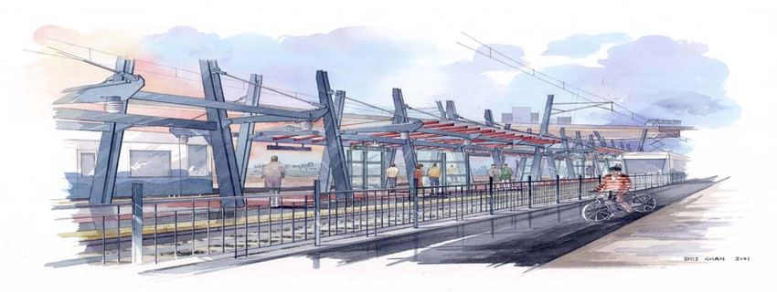
Central Link Operations Plan - Westlake to SeaTac /Airport                                                                                          July 29, 2008

                                                                    Table of Contents
SOUND TRANSIT LINK LIGHT RAIL
CENTRAL LINE OPERATIONS PLAN

  EXECUTIVE SUMMARY................................................................................................................................1
  1.1     Purpose ......................................................................................................................................................3
  1.2     Scope .........................................................................................................................................................3
  1.3     Policy Issues ..............................................................................................................................................4
  1.4     Related Documents....................................................................................................................................5
  2.0 LINK INITIAL SEGMENT / AIRPORT LINK SYSTEM DESCRIPTION.........................................6
  2.1     Alignment..................................................................................................................................................6
  2.2     Downtown Seattle Transit Tunnel .............................................................................................................9
  2.3     Stations ......................................................................................................................................................9
  2.4     The DSTT................................................................................................................................................10
  2.5     Continued Link Use of DSTT tunnel.......................................................................................................11
  2.6     Crossovers, Pocket Tracks, Tail Tracks ..................................................................................................16
  2.7     Vehicles ...................................................................................................................................................18
  2.8     Operations and Maintenance Facility ......................................................................................................19
  2.9     Traction Power System............................................................................................................................21
  2.10    Signal System and Onboard Train Control..............................................................................................23
  2.11    Communications......................................................................................................................................26
  2.12    Operations Control Center.......................................................................................................................27
  2.13    Fare Collection System............................................................................................................................28
  2.14    Passenger Service Information ................................................................................................................29
  3.0 RIDERSHIP INITIAL SEGMENT .........................................................................................................30
  3.1     Ridership Serving Major Employment Concentrations...........................................................................30
  3.2     Weekday Ridership at the Peak Load Point.............................................................................................30
  4.0 WEEKDAY RIDERSHIP BY TIME OF DAY AND LEVEL OF SERVICE ......................................31

  5.0 RIDERSHIP PROJECTIONS FOR AIRPORT LINK...........................................................................33

  6.0 SERVICE CHARACTERISTICS ............................................................................................................34
  6.1     Hours of Revenue Service .......................................................................................................................35
  6.2     Definition of Weekday Service Periods ..................................................................................................35
  6.3     Load Factors ............................................................................................................................................35
  6.4     Dwell Time and Terminal Time ..............................................................................................................36
  6.5     Running Time..........................................................................................................................................36
  6.6     Pattern of Operation ................................................................................................................................40
  6.7     Service Levels .........................................................................................................................................41
  6.8     Bus/Train Separation ...............................................................................................................................42
  6.9     Fleet Size Requirements ..........................................................................................................................46
  6.10    Operating Statistics..................................................................................................................................49
  6.11    Future Line Capacity ...............................................................................................................................49

                                                                                 ii                                                                  July 29, 2008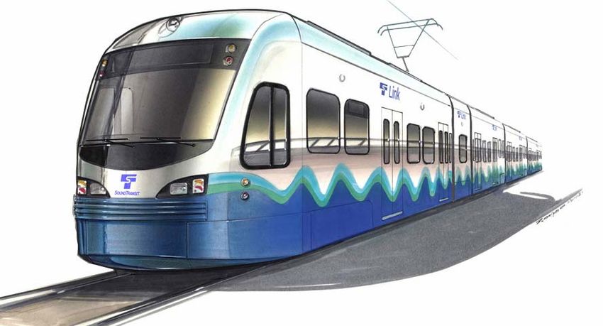
Central Link Operations Plan - Westlake to SeaTac /Airport                                                                                         July 29, 2008

  7.0 MAINTENANCE .......................................................................................................................................50
  7.1      Scheduled Maintenance on the Right-of-Way........................................................................................50
  7.2      Corrective Maintenance...........................................................................................................................50
  7.3      Equipment Access ...................................................................................................................................50
  7.4      Facility Maintenance ...............................................................................................................................50
  8.0 SAFETY AND SECURITY.......................................................................................................................51
  8.1      Incident Command and Control...............................................................................................................51
  8.2      Coordination of Rail Safety Issues ..........................................................................................................51
  8.3      Emergency Evacuation ............................................................................................................................51
  8.4      Emergency Ventilation ............................................................................................................................51
  8.5      Training ...................................................................................................................................................52
  9.0 STAFFING..................................................................................................................................................53

  10.0          TESTING AND START-UP ............................................................................................................54

  11.0          SYSTEM OPERATIONS IN DSTT................................................................................................55
  11.1 Merge Operations ....................................................................................................................................55
  11.2 Train Tunnel Operations..........................................................................................................................56
  12.0          ABNORMAL SYSTEM OPERATION ..........................................................................................58
  12.1     Causes of Abnormal Operation ...............................................................................................................58
  12.2     Failure Reporting.....................................................................................................................................58
  12.3     Failure Management Strategies ...............................................................................................................59
  12.4     Public Information...................................................................................................................................59
  13.0          SOUND TRANSIT’S OVERSIGHT OF KING COUNTY METRO LINK OPERATIONS ....61
  13.1 Performance Standards ............................................................................................................................61

Appendix A Single Line Drawing of IS/AL

                                                                                 iii                                                                 July 29, 2008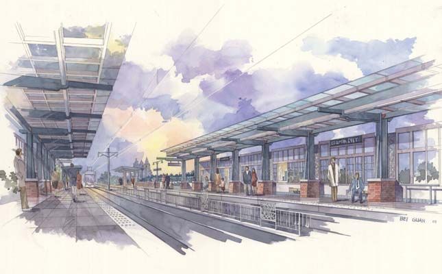
Central Link Operations Plan - Westlake to SeaTac /Airport                                                                                 July 29, 2008

                                                                       List of Figures
OPERATIONS PLAN – CENTRAL LINK
Figure 2-1  IS/AL Alignment Map .........................................................................................................................................8
Figure 2-2  Light rail and Bus layout for the DSTT                                                                                                                              12
Figure 2-3  Initial Segment – SeaTac/Airport Stations.........................................................................................................13
Figure 2-4  Intial Segment Station .......................................................................................................................................14
Figure 2-5  intial segment station ........................................................................................................................................15
Figure 2-6  Central Link Low-Floor Light Rail Vehicle ......................................................................................................18
Figure 2-7  Hybrid Bus .........................................................................................................................................................19
Figure 2-8   OMF Yard …………………………………………………………………………………… ………… 20
Figure 2-9   Traction Power Substations …………………………………………………………………… ……..                                                                                                         22
Figure 2-10 Initial Segment and Airport Link Signal Block Layout and Type .....................................................................23
Figure 2-11 Light Rail Train Signal Aspects........................................................................................................................24
Figure 2-12 Onboard Vehicle Cab Signal..............................................................................................................................25
Figure 2-13 Bus Signal Aspects in DSTT .............................................................................................................................26
Figure 3-1   Demand and Capacity IS/AL 2009 to 2010 ......................................................................................................31
Figure 6-1  Alternative Service Scenarios ............................................................................................................................40
Figure 6-2  Dstt Bus /Rail portal merge points ....................................................................................................................42
Figure 6-3  Train and Bus Movement through tunnel ........................................................................................................43
Figure 6-4  Bus /Train movement at CPS merge point .......................................................................................................44
Fifgure 6-5 Bus/Ttrain interface IDS ...................................................................................................................................45
Figure 9-1  Staffing Plan ......................................................................................................................................................53
Figure 10-1 Test track area                                                                                                                                                     54
Figure 11-1 Train/ Bus Stopping Locations at Stations.........................................................................................................56

                                                                        List of Tables
OPERATIONS PLAN – CENTRAL LINK
Table 2-1  Central Line IS/AL Alignment by Section..........................................................................................................7
Table 2-2  Central Line Passenger Stations ........................................................................................................................16
Table 2-3  Traction Power...................................................................................................................................................21
Table 2-4  Signaling by Type of Alignment........................................................................................................................23
Table 4-1  Estimated Ridership throughout the Weekday...................................................................................................32
Table 4-2  Assumed Ridership on Weekends for Service Planning ....................................................................................32
Table 5-1  Summary of Initial Segment and Airport Link Weekday Boardings .................................................................33
Table 6-1  Summary 2009/ 2010 Joint Bus / Train Operations Plan ..................................................................................34
Table 6-2  Light Rail Vehicle Capacity...............................................................................................................................35
Table 6-3  Central Link Travel Times –Initial Segment Westlake to Tukwila....................................................................37
Table 6-4  Central Link Travel Times Airport Link-Westlake to SeaTac/Airport ..............................................................38
Table 6-5  One-Way Trip Times From North Tunnel Merge Point and South Merge Point..............................................39
Table 6-6  Weekday Service Levels for IS 2009.................................................................................................................41
Table 6-7  Under development: Metro/ST Bus Routes in DSTT Under Joint Operations ..................................................41
Table 6-8   Peak vehicle requirments .................................................................................................................................46
Table 6-9   Service Level and Fleet Size Analysis for IS (Year 2009) ..............................................................................47
Table 6-10 Service Level and Fleet size Analysis for IS/Al 2010 ................................................................................................48
Table 6-11 Operating Statistics Initial Segment 2009 (2010) .............................................................................................49
Table 6-12 Operating Statistics IS/AL 2010 ........................................................................................................................49
Table 6-13 Maxuim design line capacity .............................................................................................................................49
Table 12-1 General Response to Abnormal Operations ......................................................................................................60
Table 13-1 Performance Standards ......................................................................................................................................61

                                                                              iv                                                             July 29, 2008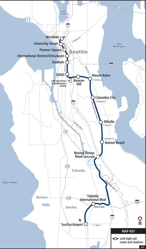
Central Link Operations Plan - Westlake to SeaTac /Airport                                 July 29, 2008

EXECUTIVE SUMMARY

The 2007 Operations Plan is a revision to the Central Link Initial Segment operating plan issued August
11, 2006. This updated version covers the Initial Segment,(IS) plus a extension south to SeaTac/Airport
(AL) The Initial Segment (IS) is defined as Westlake to Tukwila International Blvd Station.

It is the intention of this plan, that the information supplied concerning the IS and AL will be used by
King County Metro to develop their operating plans.

Studies have identified that ridership and related benefits to the mobility for the regional transportation
system increases as the Initial Segment light rail system length expands towards SeaTac/Airport and and
then will continue north to the University of Washington area.

The Central Link Initial Segment (IS) passenger service date (PSD) is scheduled for operation in mid-
2009. The Initial Segment is 13.9 miles, running from Westlake station in the Down Town Seattle
Transit Tunnel (DSTT) to Tukwila International blvd station. The IS is double tracked and contains 12
passenger stations. (One planned station at Boeing Access Road has been deferred)

Airport Link (AL) extension to the south of Tukwila International blvd station is scheduled to be ready
for operation in late 2009. The Airport Link Extension will add another 1.7 miles of track and one
additional station. The IS/AL combined will comprise 15.6 miles and will serve 13 stations. (Since the
IS will only be operational for about 6 months before the AL is added, the balance of this plan will
discuss the IS/AL except when it is necessary to describe attributes separately.)

The IS/AL train service will be provided using a two car consist, operating at various design headways
to meet ridership demand. Initial schedules have been developed allowing for 6 minute peak period
headway with a 10 minute service during the midday off peak and 15 minute early/late service.

The IS/AL will be supported by an Operations and Maintenance Facility (OMF) capable of supporting a
104 vehicle fleet at full build out. Initially, when the IS/AL first goes into service, the Operations and
Maintenance Facility will have the yard built out only to support 40 vehicles. The OMF is located in
south Seattle adjacent to the mainline and south of Forest Street and west of Airport Way.

The Link light rail vehicles (LRVs) purchased to provide the service are manufactured by Kinkisharyo
of Japan and are 95 feet in length and double articulated with a three-truck (six-axle) configuration. The
floor of the LRV will be at platform height, 14 inches from top of rail at all 4 door entries and along
approximately 70% of the length of the car. Trains can be coupled to run in one to four vehicles in
length. Vehicles will be powered by an overhead contact wire energized at 1500 volts dc, and propelled
with ac motors. Each vehicle will seat 74 passengers and have room for 74 standees the vehicle is
designed to meet all current ADA standards, supporting a capacity of 148 passengers. (This is the figure
used for scheduling purposes). During special events loading will be much higher. The IS service will
commence revenue service with a fleet of 31 vehicles. Four additional vehicles will be used for AL,
requiring a projected fleet size increase to 35 vehicles. This number of vehicles is based on supporting
2020 ridership projections.

The IS/AL will share the Downtown Seattle Transit Tunnel (DSTT) with hybrid diesel/electric buses
 operated by King County Metro. This shared use will continue until such time that increases in Link
 service and frequency requires exclusive use of the DSTT tunnel by light rail operations only.
For purposes of developing ridership projections and other planning activities, we have used a 6-minute
peak period headway based on a design year of 2020 for the Initial Segment and Airport Link. Typically,
peak hour headways developed for the initial years of operations will be different from the design year.

                                                Page 1 of 61                                  July 29, 2008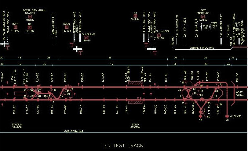
Central Link Operations Plan - Westlake to SeaTac /Airport                                   July 29, 2008

This recognizes that while initial year demand may be lower than design year demand, ridership growth
is expected to rapidly increase within the first few years of operations and therefore the need to be able
to respond to changing headway requirements to match demand. All decisions about levels of service
including headways will be subject to ST Board approval.

For the first year of operation of the Initial Segment starting in mid 2009, ridership demand is based on
projected peak hour boardings and is met by operating 2-car trains at 6-minute headways with a fleet
size of 31 light rail vehicles and with joint bus/rail services in the DSTT. For planning purposes, the Rail
Fleet Management Plan RFMP used the design year 2020 ridership projections and estimated the initial
year 2009 projections based on linear interpolation.

The Airport Link is scheduled to start operating in late 2009 or early 2010 with 2-car trains and like the
Initial Segment will operate at 6-minute headways with the addition of four light rail vehicles and with
joint bus/rail services in the DSTT. This increases the total fleet size to 35 cars. For planning purposes,
the RFMP has used the design year 2020 ridership projections and estimated the initial year 2010
projections based on linear interpolation and applied the same formula for years 2010 to 2015.

Sound Transit has entered into an Intergovernmental Agreement (IGA) with King County Metro (KCM)
the major bus operator in King County in the State of Washington, and have contracted the operations
and maintenance functions of Central Link to King County Metro. Sound Transit, as owner, will have
fiscal and performance oversight for this contract. The IGA defines performance and maintenance
standards and requirements for the operator and maintainer.

                                                Page 2 of 61                                    July 29, 2008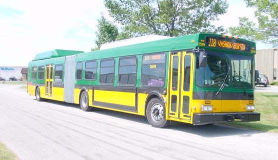
Central Link Operations Plan - Westlake to SeaTac /Airport                                   July 29, 2008

INTRODUCTION
In 1996 voters in the Central Puget Sound region approved Sound Move, the Ten-Year Regional Transit
Plan. One element of the Sound Move program was a Central Link Light Rail system. The Initial
Segment of the Central Link extends from Westlake Station in downtown Seattle to Tukwila
International Blvd station. A one station extension to the SeaTac/Airport will be constructed with plans
to continue in the future south to 200th street at a later time. The Initial Segment is scheduled to begin
service in 2009 with the extension to SeaTac /Airport opening later that same year.

 1.1     Purpose
This Operations Plan describes two segments of the light rail line, the physical characteristics for each
segment, the systems that will be used to support operations, ridership projections and the service plans
for each segment describing service frequency, train length, run times and fleet size requirements. The
plan also describes how King County Metro Buses and Sound Transit light rail trains will share common
use of the Downtown Seattle Transit Tunnel (DSTT).
The IS/AL operations plan serves as the base line document to be used for all further development of
other documents related to the operation of the Light rail system, including documents such as the
Maintenance Plan and the Rail Fleet Management Plan. The Operations Plan is also to be used as the
baseline document for setting operating ideology to be implemented for the day to day operating of the
Link light rail system.

Development of detailed operational documents such as Standard Operating Procedures (SOPs) and the
System Rule book will be based on the Operations Plan. Development of the final operating procedures
is the responsibility of the contracted operating agency. For the IS/AL, King Country Metro are the
contracted agency for operations and maintenance of the Sound Transit owned Light rail system . Sound
Transit maintains oversight responsibility over King County Metro. Responsibilities for both agencies
are defined in the Intergovernmental Agreement.

The IS/AL operations plan will be reviewed and updated as needed, to incorporate all system design
modifications and upgrades that affect the plan. An update will be done after the opening of the IS so
lessons learned can be applied to the combined IS/AL LRT system.

 1.2     Scope
The plan provides information about the Initial Segment and Airport Link.(IS/AL). Information
contained in the document is based on information and ridership projections contained in the RFMP and
describes projected hours of service, headways, projected ridership, estimated run times and guideway
route miles for the various line segments. Included in the plan is a short description of the various station
locations, designs, and types of platforms.

                                                Page 3 of 61                                    July 29, 2008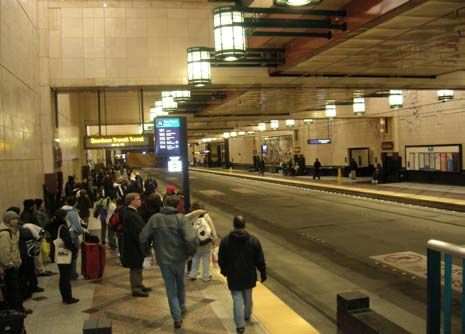
Central Link Operations Plan - Westlake to SeaTac /Airport                                  July 29, 2008

 1.3     Policy Issues
The following policy issues have been addressed for the IS/AL.

        •    DSTT Control Room:
             Sound Transit and King County Metro have agreed that the preferred method of controlling
             the DSTT is for one agency to have control of facilities and equipment for all movements of
             buses and trains in a single location. KCM Link light rail staff will operate a single control
             room located at the new Metro Communication Command and Control Center. (MCC&C)
        •    Bicycle Policy:
             King County Metro restricts loading and unloading of bicycles to IDS and CPS stations
             only. A uniformed policy will be developed to meet both agencies needs before PSD date.
        •    Ride Free Zone:
             Both agencies will continue to operate the free ride zone in the DSTT during the ride free
             hours
        •    Security within the DSTT:
             King County Metro is responsible for security in the DSTT.
             Sound Transit has contracted private security to cover the areas outside the DSTT tunnel.
             The Security Plan is under development and will deal with the issue of uniformed law
             enforcement officers and address any jurisdictional issues.
        •    Lost and Found:
             King County Metro will manage and administer all Link lost and found articles.

                                                Page 4 of 61                                   July 29, 2008
Central Link Operations Plan - Westlake to SeaTac /Airport                             July 29, 2008

 1.4     Related Documents
The Link Operations Plan relies on information contained in several other documents developed for the
Initial Segment and Airport Link. These include the latest revisions of the following:

        •        Rail Fleet Management Plan (RFMP)

        •        Bus Fleet Management Plan (BFMP)

        •        IS/AL Maintenance Plan (MP)

        •        Intergovernmental Agreement between Sound Transit and King County Metro,
                 June 2003 (IGA)

        •        Link System Safety Program Plan (SSPP) (Under development )

        •        Link System Security Plan (SSP) (Under development )

        •        Systems Integrated Test Plan (SIP)

        •        Design Criteria Manual (DCM)

        •        IS / AL Project Management Plan (PMP)

        •        Joint Bus /Rail Operations in the DSTT Operations Plan

        •        Rail Activation Plan

                                                Page 5 of 61                              July 29, 2008
Central Link Operations Plan - Westlake to SeaTac /Airport July 29, 2008
2.0 LINK INITIAL SEGMENT / AIRPORT LINK SYSTEM DESCRIPTION
The Initial Segment and extension to the Airport is the backbone of a regional light rail transit system
with future plans for extending into Pierce and Snohomish counties which will link the downtown area
of Seattle, Tacoma and Everett together. The first constructed segment of the line extending from
Westlake Station to SeaTac/Airport is entirely within King County. An extension north to the
University of Washington is now in final design phase engineering with an additional extension south of
the airport station to south 200th street proposed.
2.1 Alignment
The Central Link Initial Segment is 13.9 miles from Westlake station in downtown Seattle to Tukwila
International Blvd station in the city of Tukwila. The line will then be extended 1.7 miles to SeaTac
Airport in the City of SeaTac. The extension will result in a baseline IS/AL system of 15.6 miles.
The Initial Segment alignment consists of various types of rights-of-way, which include exclusive at-
grade, tunnel, aerial sections, street median and gate-protected semi-exclusive sections. The light rail
link utilizes the existing Downtown Seattle Transit Tunnel (DSTT) and the newly constructed Pine
Street Stub Tunnel to travel under the downtown business district. South of the DSTT the line continues
for a short distance at grade, turns east on aerial structure and into a dual tunnel under Beacon Hill, exits
onto aerial then transitions to grade. Continuing south, the line runs in street median along Martin Luther
King Jr. Way (MLK Way) in the Rainier Valley where once again it transitions to aerial and at grade,
operating through the City of Tukwila. A short extension to the Airport in the city of SeaTac will
consist of aerial guideway and exclusive at-grade sections The IS/AL line is double tracked for the full
length and the tracks are of standard gauge.
The IS/AL takes advantage of the flexibility of light rail technology by incorporating several types of
right-of-way including sections of fully separated tunnel and aerial guideway, partially separated at-
grade, highway medians, and street operation. The types of right-of-way on which the IS/AL line will
operate are described below and shown in the Table 2.1.
Exclusive: The right-of-way is separated from and completely inaccessible to non-rail transit
vehicles and the general public. Includes subways, aerial structures, and at-grade segments
Semi-exclusive (protected): This at-grade private right-of-way is separated from parallel traffic,
but crosses intersecting streets. Light rail trains have priority at all grade crossings, which are
protected by crossing gates, lights and bells.
Semi-exclusive (street median): This at-grade right-of-way is separated from parallel traffic, but
crosses streets at grade. Street crossings are furnished with traffic signals to govern vehicular,
pedestrian and train movement, but are programmed to grant priority to light rail trains. The
right-of-way may be protected from parallel traffic by high unmountable curbs, barriers, or
safety fences; or separation may be indicated by mountable curbs, striping, or signage.
Mixed bus/rail in the twin bore tunnel: Light rail trains share the existing downtown Seattle
transit tunnel (DSTT) with transit buses. Safe separation between trains, buses and other trains
are governed by SOP’s and rules and proper use of the wayside signal system. Trains may not
enter a tunnel segment between stations when that segment is occupied by a bus. Buses may be
platoon with the authorization of the OCC.
Page 6 of 61 July 29, 2008Central Link Operations Plan - Westlake to SeaTac /Airport July 29, 2008
Table 2-1 Central Line IS/AL Alignment by Section
Section Miles Stations Alignment Type Description
Downtown 1.3 Westlake Bus Shared Downtown
Seattle University Street Exclusive Seattle Transit
Pioneer Square tunnel Tunnel (existing)
International District/Chinatown
South Seattle 2.3 Stadium Semi-Exclusive Along E3 bus
SODO Gate crossing way
Beacon Hill Exclusive Aerial on Forest;
Aerial : tunnel Tunnel under
Portal to Portal Beacon Hill
Rainier Valley 4.7 Mount Baker Exclusive: Aerial Aerial at MT
Columbia City Semi –Exclusive: Baker
Othello Street median Street Median
Rainier Beach on MLK Jr. Way
City of Tukwila 5.6 Tukwila International Blvd Excusive: Aerial Aerial: Boeing
and at-grade Access Road to
Tukwila Internat’l
Blvd w/ some
exclusive at-
grade ROW
Sea-Tac /Airport 1.7 Sea Tac /Airport station Exclusive; Aerial Aerial from
Station and at grade Tukwila Internat’l
to airport
property down to
grade and aerial
again at 170th
Street to airport
Sea/Tac station
Total 15.6
Page 7 of 61 July 29, 2008Central Link Operations Plan - Westlake to SeaTac /Airport July 29, 2008
Figure 2-1 IS/AL Alignment Map
Page 8 of 61 July 29, 2008Central Link Operations Plan - Westlake to SeaTac /Airport July 29, 2008
Operating speeds will vary according to the type of right of way, civil alignment characteristics and
special local conditions. In general, maximum designed allowable speeds along the Central line will be:
• Exclusive right of way: 55 mph
• Semi-exclusive right-of-way (protected): 45 to 55 mph
• Semi-exclusive right-of-way (street median): posted speed limit of parallel street; on MLK Way,
the posted speed limit is 35 mph.
• Mixed bus/rail downtown twin bore tunnel 35 mph or less operational speed will be the posted
speed. There is a 10 mph protected at the un-gated DSTT merge points.
2.2 Downtown Seattle Transit Tunnel
In the Seattle Central Business District, trains will operate through the existing Downtown Seattle
Transit Tunnel (DSTT), making stops at the existing International District/Chinatown Station, Pioneer
Square Station, University Street Station, and Westlake Station. King County currently uses the tunnel
for Metro bus service and operates some of Sound Transit’s routes. When light rail services starts, both
buses and trains will jointly operate in the existing tunnel. South of the DSTT tunnel portal, the E3 Bus
way continues on a reserved right-of-way for 1.1 miles. The light rail tracks will be located on a parallel
right-of-way directly to the east of the bus way alignment. There are two stations located along the E3
bus way . Stadium light rail station is located in the area just south of Royal Brougham Street, the first
crossing street reached from the DSTT south portal. SODO station is the other station located south of
Stadium. The track along this area is the test track area for the Light Rail system.
2.3 Stations
The IS/AL will have 13 operational passenger stations with a deferred station at Boeing Access Road.
Stations are located in tunnels, on aerial segments, and at ground level. The stations will have either a
center platform served by both tracks, or two side platforms, one for each direction of travel. Table 2-2
provides information for each station. Average station spacing by area is shown below.
Average station spacing (miles between stations)
Downtown Seattle (Westlake – International District) 0.3 miles
South Seattle (International District – Rainier Beach) 1.1 miles
Tukwila (Rainier Beach – Tukwila International blvd) 5.6 miles
Airport Link (S154th to SeaTac-Airport) 1.7 miles
All stations will have platforms that are a minimum of 380 feet long (existing stations in the DSTT have
400-foot long platforms). Station platforms will be 14 inches (350 mm) above top of rail, to match the
level of low-floor LRVs and hybrid diesel/electric buses in the DSTT. All at-grade stations have
passenger access walkways and ramps. Aerial and tunnel stations will be furnished with stairs,
elevators, and escalators. Each station will have ticket vending machines, smart cards, closed-circuit
television and public address systems and variable message signage. Tunnel stations have systems that
monitor and control ventilation and emergency phones using the SCADA (Supervisory Control and
Data Acquisition) system that allow the Operations Control Center (OCC) to perform the majority of
Fire/Life safety functions. The SCADA system will automatically respond to defined fire /Life safety
alarm points.
Page 9 of 61 July 29, 2008Central Link Operations Plan - Westlake to SeaTac /Airport July 29, 2008
2.4 The DSTT
The DSTT is 1.3 miles long. Prior to the tunnel closure for Link light rail modifications in September
2005, twenty one bus routes utilized the tunnel with a peak of up to 70 buses per hour in each direction.
All buses in the tunnel are operated by King County Metro. The existing tunnel is being modified by
addition of a 750’ stub tunnel north of Westlake Station to provide a crossover and turnback track under
Pine Street. The four LRT/Bus stations in the DSTT alignment, and one bus only station just outside the
north portal, are:
• International District /Chinatown Station (IDS): the southernmost station. It is a partially covered
station beneath a plaza adjacent to 5th Avenue at Jackson Street.
• Pioneer Square Station (PSS): an underground station under 3rd Avenue at Yesler Way.
• University Street Station (USS): an underground station under 3rd Avenue at University Street. The
station has direct access to Benaroya Hall (Seattle Symphony venue) above.
• Westlake Station (WLS): is an underground station under Pine Street at 5th Avenue. This station has
direct access to the Macy’s and Nordstrom department stores and the Westlake Center via a
mezzanine.
• Convention Place Station (CPS): is an open-air station just outside the north portal (at 9th Avenue
and Pine Street). The station facilities are located in open cut beneath street level. This station is not
being served by light rail.
Buses access and exit the DSTT from the south by three routes:
• A surface roadway that is part of the E3 Bus way, just north of its intersection with Royal Brougham
Way.
• Exclusive express bus ramps from the I-90 Transitway.
• Buses completing a southbound trip terminating at IDS turnback in the staging area to layover or
begin a northbound trip.
• Buses completing a southbound run through the DSTT can be scheduled to use this area to turn
around and layover prior to commencing a northbound run through the tunnel.
• When the tunnel re-opens there will be no bus trolley operation required in the tunnel. All buses
that use the tunnel will be diesel/electric.
• Bus operation will remain relatively unchanged with the exception of stringent adherence to signal light
indications and the ability with Operations Control Center to authorize platooning of buses.
Buses access and exit the DSTT from the north via three routes as well:
• Reversible ramp leading directly from the express lanes of I-5.
Page 10 of 61 July 29, 2008Central Link Operations Plan - Westlake to SeaTac /Airport July 29, 2008
• Surface access entrance ramps at the corner of 9th and Olive Way and an exit ramp to Olive
Way.
• Buses completing a northbound trip terminating at CPS turnback in the staging area to layover
or begin a southbound trip.
• At the north end of the tunnel, buses change modes at CPS either in the staging area or at the
platforms. Bus layover area and turnaround lanes are provided immediately north of the CPS
platforms in the open cut commonly referred to as the CPS staging area.
The four underground stations – IDS, PSS, USS and WLS – have two side platforms, each 380-390 feet
long. Each platform has two designated stopping locations (“bays”) for specific bus routes. There is a
passing lane in the center of each of the four stations, to enable buses in either direction to operate
around other buses stopped in the station. CPS has four side platforms, a long one for all northbound
buses, and three shorter platforms with bay designations for southbound service entering the tunnel. A
passing lane is provided between outbound Bays A/B and inbound Bay # 1.
The tunnel between IDS and WLS is composed of two single mined bores, each bore accommodating
one lane. The alignment between WLS and CPS is two-lane cut/cover.
2.5 Continued Link Use of DSTT Tunnel
The IS/AL base line segment runs from a terminal train turn-back facility in exclusive tunnel east of
Westlake station under Pine Street referred to as Pine street stub tunnel, to SeaTac/Airport station. The
planned turn back arrangement for the Pine street stub tunnel cross over is displayed in figure 2.2.
In the DSTT, one track will be located in each tunnel bore and serve each side platform. A platform
height of 14 inches (measured from top of rail) will permit level boarding of both low-floor buses and
light rail vehicles. CPS station is a bus only station just outside of the DSTT’s north end of the tunnel.
There are two bus/ rail merge points identified for the DSTT one is at IDS and the another at CPS.
There is one bus turn around location just south of the IDS platform. This turn back point is protected
by railway crossing flashing lights but has no gates due to no clearance issues .
There are gates and railway type flashing light protection for bus merge points south of IDS which is
considered part of the IDS merge points. These locations protect buses merging from the I 90 and buses
coming off the E3 bus way.
Figure 2-2 below details the layout for the DSTT both bus and trains routes are indicated in the figure.
Page 11 of 61 July 29, 2008Central Link Operations Plan - Westlake to SeaTac /Airport July 29, 2008
Figure 2-2 Light Rail and Bus layout for the DSTT tunnel area.
+
Page 12 of 61 July 29, 2008Central Link Operations Plan - Westlake to SeaTac /Airport July 29, 2008
Figures 2-3 Initial Segment – SeaTac/Airport Stations
Westlake Station:
Pioneer Square Station:
Primary station serving the retail area of downtown
This station serves the historic area of old Seattle and
Seattle. Side platform tunnel station with full
jurisdictional facilities. Side platform tunnel station
mezzanine access from numerous retail establishments.
with mezzanines at each end.
University Street Station: International District Chinatown Station:
Station serves numerous offices in the downtown core, the Station accesses the International District of Seattle,
Public Market, the Seattle Art Museum and Benaroya Hall. Qwest and Safeco stadiums. Side platform retained cut
Side platform tunnel station. station with direct access to plaza at street level.
Closest station to connect to/from Sounder Commuter
rail and Amtrak at King St station.
Page 13 of 61 July 29, 2008Central Link Operations Plan - Westlake to SeaTac /Airport July 29, 2008
Figure 2-4
Stadium Station
Serves Qwest Field and Safeco Field Stadiums at Royal Brougham Blvd.
SODO Station: Beacon Hill Station:
Serves the SODO District of Seattle. Side Serves the primarily residential Beacon Hill
platform at grade station. Station is adjacent to a neighborhood and neighborhood businesses and
bike trail and a greater number of bicycle storage services. Deep tunnel station with twin tube tunnels.
Single entry station with high-speed elevator only
is provided at this station.
access.
Mount Baker Station serves North Rainer area Columbia City Station serves Rainer Vista
Page 14 of 61 July 29, 2008Central Link Operations Plan - Westlake to SeaTac /Airport July 29, 2008
Figure 2-5
Rainier Beach Station:
Serves residential and the industrial area to the south of
Othello Station: the station. Single entry center platform at grade station.
Located in the heart of a neighborhood commercial area. Operator's building is located at the south end of the
Double end loaded, side platform at grade station with two platform with staff washroom, janitor's closet,
adjacent plazas at each end. supervisor's office and staff workroom. One plaza is
located to the north of the station
S. Tukwila International Blvd: SeaTac/Airport
Transit facility accommodates park and ride, bus layover and Terminus station bus loop and passenger drop off
bus bays, passenger drop off. area.
Page 15 of 61 July 29, 2008Central Link Operations Plan - Westlake to SeaTac /Airport July 29, 2008
Table 2-2 Central Line Passenger Stations
Miles from last
STATION station Station type Platform Type
Westlake Tunnel Side
University St 0.3 Tunnel Side
Pioneer SQ 0.4 Tunnel Side
International District/ China Town 0.4 Tunnel Side
Stadium 0.5 At Grade Center
SODO 0.7 At Grade Side
Separated
Beacon Hill 1.0 Tunnel Center -Side
Mount Baker 0.7 Aerial Side
Columbia City 1.2 At-Grade Side
Othello 1.6 At-Grade Side
Rainier Beach 1.1 At-Grade Center
Tukwila Int Blvd Station 5.6 Aerial Side
SeaTac/Airport 1.7 Aerial Side
2.6 Crossovers, Pocket Tracks, Tail Tracks
Crossovers, pocket tracks and tail tracks are referred to as “special trackwork.” This distinguishes them
from the regular tracks that guide trains from point to point. Strategic placement of special trackwork is
critical to dependable and efficient operation of train service.
Crossovers are composed of track switches that enable trains to move from one track to another.
Crossovers are located at terminal stations to enable trains arriving on the inbound track to cross over to
the other, outbound track for departure in the direction from which it arrived. Additional crossovers are
placed along the line to enable trains to be routed around system blockages or scheduled maintenance
that requires removing one track from service. Crossovers have been spaced two to three miles apart to
support the 15 minute single-tracking headway specified in the design criteria.
Pocket tracks are storage tracks located between and having access to the two mainline tracks. They are
used to turn back trains at intermediate points or at a terminus to store gap or build-up trains, store trains
with critical faults off the mainline track, or store non-revenue maintenance equipment.
Tail tracks are typically provided at the ends of the line to enable trains to be stored temporarily at these
terminal stations without occupying the platform tracks needed for revenue service. Tail tracks also
enable trains to enter terminal stations at higher speeds, as they provide a longer “safe braking distance”
Page 16 of 61 July 29, 2008Central Link Operations Plan - Westlake to SeaTac /Airport July 29, 2008
(i.e., the distance considered necessary for all trains, including those experiencing baking problems, to
safely stop). Tail tracks can also be used to store gap trains and trains with critical faults.
For the Pine Street Stub tunnel there is a 300 feet long stub track to support 3 car train movement. (This
is not significant since four car consists will not be used north of Stadium Station until the Central Link
extends north out of Westlake station ,).
Two midline pocket tracks are located on the IS/AL line – one just south of the Stadium and another in
SODO just south of Rainier Beach station on MLK Way at Henderson, Both locations are in at-grade
areas. Their location places them at intervals approximately five miles apart and close to passenger
stations. The pocket track at Stadium station is 400 feet—long enough to accommodate the longest train
operated on the system. Stadium pocket location will be strategic for staging trains to accommodate
stadium special event crowds. The pocket track at Rainier Beach is 800 feet with the capability of
accommodating two 4 car trains. For failure management and optional peak service the pocket tracks can
be used for scheduled turnbacks.
For SeaTac /Airport station a crossover is located north of the station platform. This will enable
southbound trains to enter the station at either side of the center platform. Train operators will reverse
train direction while at the platform. At the scheduled departure time trains will leave the station on the
northbound track. Due to the Airport station status as a temporary terminal and due to civil constraints,
no tail track is being provided for at SeaTac/Airport station. There is 103 feet of track beyond the
platform to allow trains to enter the platform at reasonable speed while still meeting safe braking
distance requirements. See appendix A for track alignment showing all special track work .
Page 17 of 61 July 29, 2008Central Link Operations Plan - Westlake to SeaTac /Airport July 29, 2008
2.7 Vehicles
2.7.1 Light Rail Vehicle
The light rail vehicles for the system are electrically-powered cars that can be operated individually or
in multiples of up to four. For the IS/AL 2 and 3 cars are supported for a Westlake to Airport trip. A
drawing of the light rail vehicle is shown in figure 2-7 below. A Kinkisharyo design vehicle has been
selected for the system. The car is 95 feet long with an articulation in the center to enable the car to
negotiate tight radius curves. It is a low-floor vehicle, with four sets of doors on each side and an
operator cab at each end for operation in either direction. The vehicle has a railway high intensity light
over each cab which operates during all operating hours. The car draws its power by roof-mounted
pantographs from an overhead contact wire, energized at 1500 volts DC and converted to three-phase
AC using inverters on board the vehicles. Motorized trucks (wheel assemblies) are of conventional
two-axle, four-wheel design. Each powered axle has its own AC traction motor. Over the motorized
trucks, the car floor is roughly 39 inches above the rail. The car's mid-section, roughly 70% of the
passenger compartment, including all passenger entryways, has floors approximately 14 inches above
the rail to provide level boarding from platforms of the same height. The center truck under the
articulation section is not powered and is designed with four stub axles to enable the 14-inch floor
height to continue through the articulation section. Steps in LRV aisles enable passengers to move
from entries to end-of-car seating areas above the motored trucks.
Interior seating is arranged mostly in a 2 + 2 transverse pattern, with half the seats facing one way and
the other half in the opposite direction. Inward-facing longitudinal seats are furnished where required
to facilitate passenger circulation around entries and through the articulation sections. Flip-up seats
adjacent to each door open up to four areas for patrons in wheelchairs. Racks are also provided near
inner door vestibules for stowing bicycles and luggage.
Figure 2-6 Central Link Low-Floor Light Rail Vehicle
High Floor Low floor High floor
Page 18 of 61 July 29, 2008Central Link Operations Plan - Westlake to SeaTac /Airport July 29, 2008
2.7.2 Buses
Hybrid diesel-electric battery low floor coaches will be used in the DSTT. The power source will not
interfere with the overhead contact wire of the light rail system and will be compatible with ventilation
of the DSTT.
The low floor bus is designed to enable wheelchair users to directly board the bus from the DSTT 14”
high platforms using wheelchair ramps instead of lifts.
Figure 2-7 Hybrid Bus
Sound Transit’s Kinkisharyo /Mitsui
2.8 Operations and Maintenance Facility
An OMF located at Forest and Airport Way immediately adjacent to the mainline in south Seattle
houses all maintenance and most operations functions. With the facility fully built, the yard is capable
of storing 104 95-foot vehicles. It will be initially built to accommodate 40 vehicles sufficient for
storage for the IS/AL fleet through 2020. The yard is equipped with a car wash. The main shop
building is fully equipped to undertake service, inspection, and heavy repair functions for the light rail
vehicles. Rail Operations and Fleet Maintenance offices are located in the building. Vehicle and
ROW maintenance activities and staff are also based at this site. Indoor and outdoor storage are
provided to store spare parts for vehicles, support systems. The back up Link Operations Control
Center (OCC) is also included in this complex.
For the IS/AL, storage tracks are provided to support up to 40 cars, while the initial IS/AL fleet will
only be 35 vehicles. With an ultimate design capacity of 104 cars, the yard track may be expanded as
need arises. Included in the yard design is a run-around track to ensure that cars can always be routed
around the yard without obstruction. Two access points are provided for all locations in the yard to
ensure that a single obstruction will not block in any vehicle. Dual access points are provided for
entry to and from the mainline, and for each yard track and each shop track. A site plan of the
Operations and Maintenance Facility shown as figure 2.9 The plan shows the facility at full build-out,
identifying those tracks and buildings that will be required for further extensions.
Page 19 of 61 July 29, 2008Central Link Operations Plan - Westlake to SeaTac /Airport July 29, 2008
Figure 2-8 Central Link Operations and Maintenance Facility
South
Bound Main Line
Yard Main
Lead Entrance
Backup
Airport Way
Final yard layout shown here.
Only the 5 storage tracks
nearest the shop installed to
support the IS/AL
The remaining 9 storage
tracks will be built for UL
MOW Shop Operations Center/
Deferred Offices/ Shops
Parking
Forest St Laydown Area LRV Shops
Entrance
Main
Yard
Lead
North
Bound
Page 20 of 61 July 29, 2008Central Link Operations Plan - Westlake to SeaTac /Airport July 29, 2008
2.9 Traction Power System
For the IS/AL power for trains will be provided by a series of 11 traction power substations and 1 tie
station distributed along the line which converts commercial power to 1500 volts direct current (Vdc).
Substations are designed to permit power to be provided to a line segment by the adjacent substation in
the event of loss of one substation. Light rail substations for a 1500-volt system are typically spaced
approximately one mile apart.
Power is distributed from substations to trains by means of the overhead contact system (OCS). The design of the OCS
is matched to the type of right-of-way:
• New tunnel sections and DSTT: A very low profile fixed-terminated OCS, with span lengths of 60 feet and
contact wire height of 13 feet 6 inches.
• Aerial structures: Auto-tensioned OCS, with span length of 200 or more feet on tangent track, and a contact
wire height of 16 feet.
• Street running sections: Auto-tensioned OCS design.
• Yard and shops: Single contact wire fixed-terminated OCS.
The OCS is sectionalized to enable particular sections of catenaries to be isolated and de-energized, without forcing a
curtailment of train operations on other adjacent sections of the line. Sectionalizing is normally located at substations,
crossovers, and pocket tracks. Power is monitored and controlled through the SCADA system from the OCC.
Table 2-3 Traction Power
Facility Name
Station Jurisdiction Physical Location
Pine Street TPSS Seattle 100FT. W. Boren Ave. beneath Pine Street
International TPSS Seattle IDS Tunnel South Staging area beneath Airport
District/Chinatown Way
Forest Street TPSS Seattle O&M Facility - South of S. Forest St., West of
Airport Way under aerial guideway
O&M Facility Shop TPSS Seattle Inside O&M Facility - South of S. Forest St.,
West of Airport Way
Mt Baker . TPSS Seattle West of 26th Ave. S. between S. Forest St. &
McClellan St.
Columbia City TIE Seattle Columbia City Plaza – E. of MLK Jr. Way S.,
North of S. Columbia City St.
Othello TPSS Seattle Myrtle Plaza - East of MLK Jr. Way S., North
of S. Myrtle St.
Rainier Beach St. TPSS Seattle East of MLK Jr. Way S., South of S. Rainier
Beach St.
Boeing Access Rd. TPSS Tukwila East of E. Marginal Way S., South of Boeing
South 133rd St. TPSS Tukwila West of SR 599, South of S. 133rd St.
South 154th Street TPSS Tukwila East of International Blvd. South of S. 154th St.
SeaTac/Airport Station TPSS SeaTac North of Airport Station under crossover
Page 21 of 61 July 29, 2008You can also read