Status of the Sentinel-3 SLSTR Performance and Calibration - 1RAL Space, Science and Technology Facilities Council, UK 2National Physical ...
←
→
Page content transcription
If your browser does not render page correctly, please read the page content below
Status of the Sentinel-3 SLSTR Performance and Calibration

 Dave Smith1, Ed Polehampton1, Mireya Etxaluze1, Sam Hunt2

 1RAL Space, Science and Technology Facilities Council, UK
 2National Physical Laboratory, UK

© ACRI-ST | S3MPC – 2014-2016
Post Launch Calibration – The Challenge

 Establishing absolute radiometric calibration of TIR sensors using terrestrial sites is
 restricted by:
 v Knowledge of surface emissivity
 v Surface non-uniformity
 v Temporal variations over short time (effect of surface winds, cloud shadow, solar elevation)
 v Contribution of Atmosphere to the measured signal

 Hence limited to:
 v Monitoring of instrument parameters
 v Monitoring of on-board calibration sources
 v Satellite inter-comparisons
 v Validation of L2 data products

© RAL Space | S3MPC – 2017 2
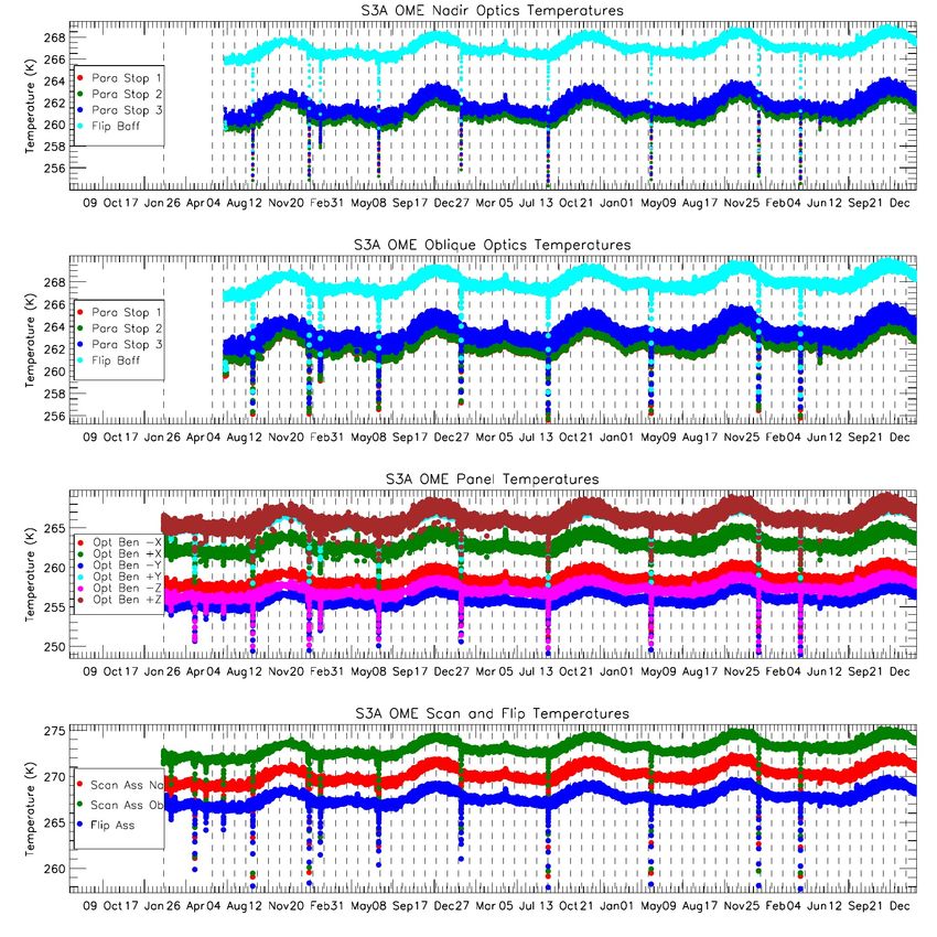
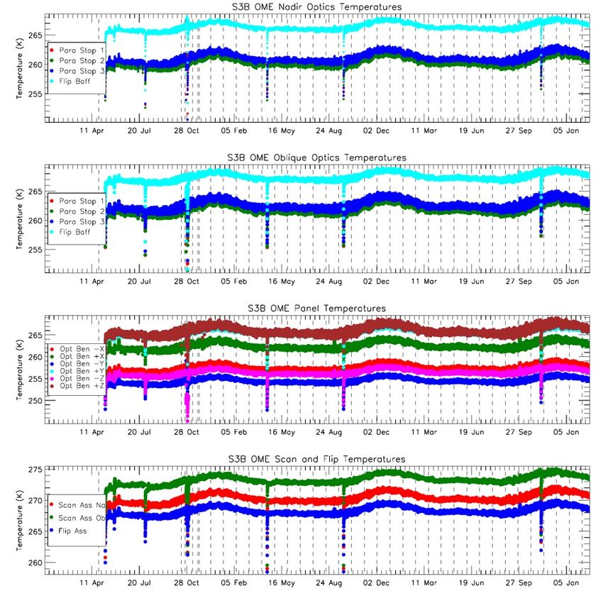
SLSTR Thermal Performance

 As a thermal IR instrument, stability & uniformity of instrument temperatures is
 critical to radiometric calibration
 SLSTR-A SLSTR-B

 2016 2017 2018 2019 2020. 2021 2018 2019 2020. 2021

© RAL Space | S3MPC – 2017 3
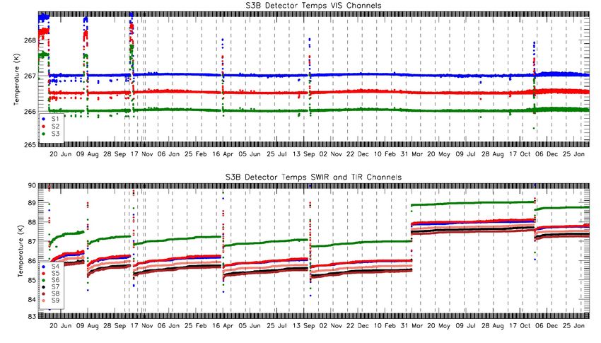
Detector Temperatures

 SLSTR-A VIS Detectors

 IR detector temperatures maintained between 84 K
 and 89 K
 IR Detectors

 Periodic de-contamination is needed to remove
 water ice from cold surfaces

 2016 2017 2018 2019 2020. 2021
 SLSTR-A FPA Cooler set-point increased by 1 K in
SLSTR-B VIS Detectors July 2018 and 1 K in Oct 2020 to increase running
 time between decontaminations

 SLSTR-B FPA Cooler set-point increased by 2 K in
 March 2020

 IR Detectors

 2018 2019 2020. 2021

© RAL Space | S3MPC – 2017 4
Cryocooler Performance

Cryocooler control maintains the cold-tip to a constant set SLSTR-A
point temperature

FPA and detector temperatures are not directly controlled and
increase during operational cycle due to increase in heat load
caused by build up of water ice on heat shield

Periodic decontamination is performed to remove ice and
‘reset’ cooler. SLSTR-B

Despite reduction in water ice, successive decontaminations
have shown steady increase in compressor amplitude at start
of operational cycle.

To reduce frequency of decontaminations and to maintain the
cooler lifetime set point temperature has been increased AND
compressor amplitude limit has been increased.
 © RAL Space | S3MPC – 2017 5

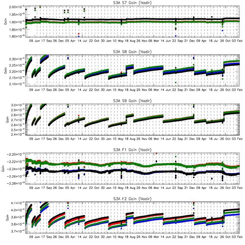
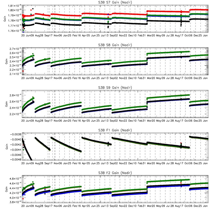
IR Channels Gains

 SLSTR-A SLSTR-B
All detectors are performing
as at launch within expected S7
ranges
 S8

Gains and offsets show slow
drift with detector S9
temperature as expected.
 F1

 F2

 2016 2017 2018 2019 2020. 2021 2018 2019 2020. 2021

© RAL Space | S3MPC – 2017 6
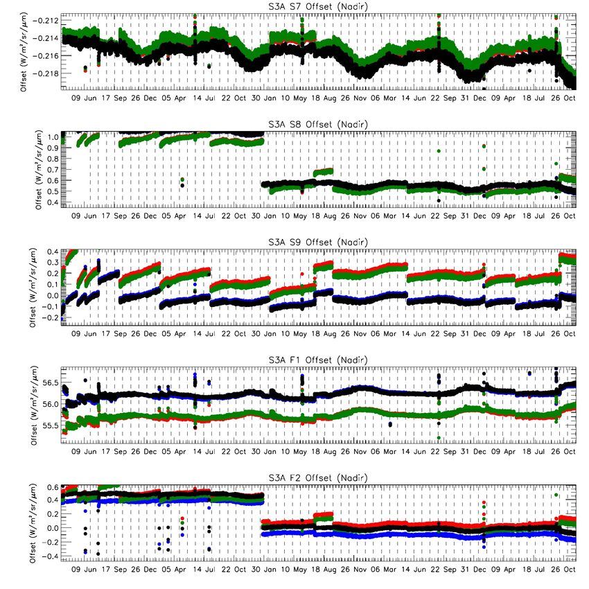
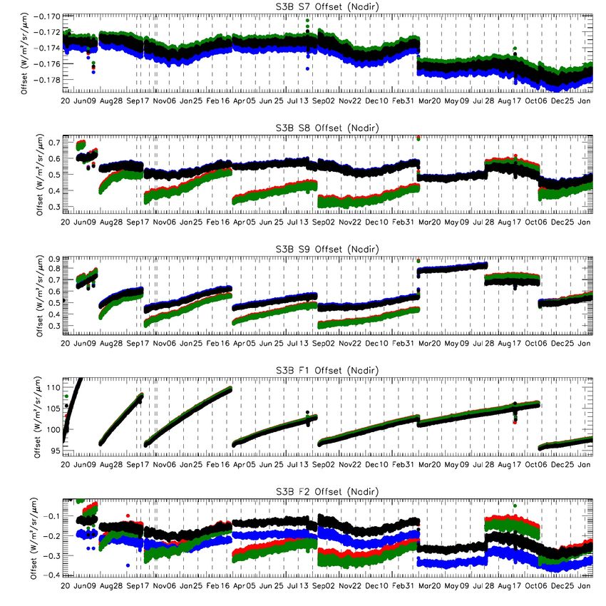
IR Channels Offsets

 Offset variation is dependent on SLSTR-A SLSTR-B
 detector temperature and thermal
 background drift.
 S7
 S3A:
 S8 offsets updated 26th Jan 2021:
 Lower limit of dynamic range S8
 following update is ~180 K for S8,
 and
IR Channels Noise
 SLSTR-A SLSTR-B
Radiometric noise levels for the
TIR channels have remained S7
stable throughout at pre-
launch values.
 S8
NEDT for the S8 and S9
channels are below 20mK with
no indication of degradation. S9
Small increase in NEDT after
change of cooler set-point
temperature. F1

S3B F1 shows periodic
increases in noise – possibly F2

due to motional chopping

© RAL Space | S3MPC – 2017 8
IR Channels Noise vs Detector Temperature
 SLSTR-A SLSTR-B

 From mission trends we can
 assess the sensitivity of the
 NEDT as a function of detector
 temperature.

 Analysis suggests that NEDT
 would be within target
 requirement for temperatures
 up to 90K – although this has
 other consequences i.e.
 Spectral response variaton

© RAL Space | S3MPC – 2017 9
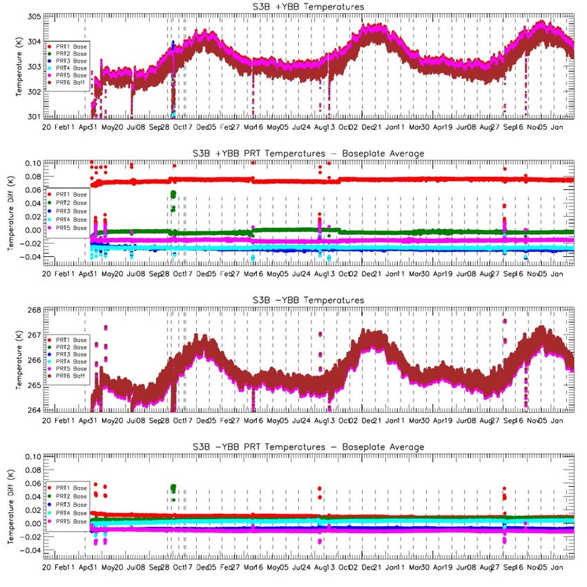
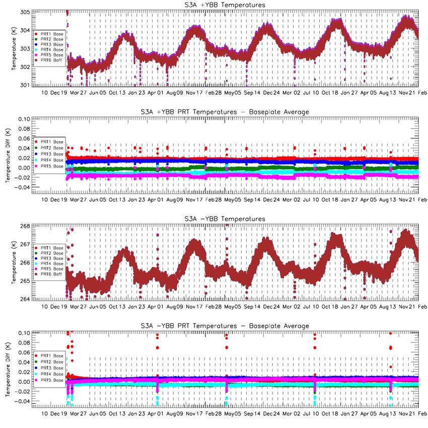
Black-Body Performance

 SLSTR-A SLSTR-B
 Blackbody temperatures have a
 seasonal cycle on top of the
 daily/orbital temperature cycles.
 Heated BB remains below 305K +YBB
 limit necessary for S7 calibration.

 Temperature gradients consistent
 with pre-launch values for SLSTR-
 A and B
 -YBB
 Note higher gradient in heated BB
 for SLSTR-A
 2016 2017 2018 2019 2020. 2021 2018 2019 2020. 2021

© RAL Space | S3MPC – 2017 10
Blackbody Cross-Over Tests

 • The basic idea is to compare the radiometric signals in the thermal channels when the two blackbodies
 are at identical temperatures.

 • Any significant difference would imply a drift in the blackbody thermometer calibration or change in
 target emissivity caused by a deterioration of the black surface finish.

 • This follows the approach taken for AATSR and will be performed for SLSTR in-flight during
 commissioning and at yearly intervals to determine any changes in the blackbody performance.

 • The test was performed by switching the heated blackbody from the +YBB to the –YBB (and vice versa)
 and allowing the temperatures to cross over and stabilise.

© RAL Space | S3MPC – 2017 11
Blackbody Cross-Over Test Execution

 • Part-1 of the test +YBB off and –YBB heated
 S3A Nadir – Part 1 S3B Nadir – Part 1
 v S3A Crossover occurred at 01-OCT-2020
 10:01:29
 ü BB Temperatures were 290.284K
 v S3B Crossover occurred at 28-SEP-2020
 14:00:32
 ü BB Temperatures were 289.785K

 • Part-2 was performed -YBB off and +YBB
 heated
 v S3A Crossover occurred at 02-OCT-2020
 10:49:52
 ü BB Temperatures were 291.774K
 v S3B Crossover occurred at 29-SEP-2020
 14:41:11
 ü BB Temperatures were 291.070K

© RAL Space | S3MPC – 2017 12
BB Cross-Over Test Analysis – SLSTR-A

 Part 1 Part 2
 Difference in counts at
 cross-over equates to
 temperature difference
 where

 !"
 ∆ = ∆
 !#

 Note difference between
 Parts 1 and 2 of test

© RAL Space | S3MPC – 2017 13
BB Cross-Over Test Analysis – SLSTR-B

 Part 1 Part 2

 Difference in counts at
 cross-over equates to
 temperature difference
 where

 !"
 ∆ = ∆
 !#

 Note difference between
 Parts 1 and 2 of test

© RAL Space | S3MPC – 2017 14
BB Cross-Over Test Results Time-Series
 SLSTR-A Part-1 SLSTR-B Part-1

 Results show S8 and S9
 are stable over mission
 duration for both S

 S3A S7 shows gradual drift
 with part 1 (-YBB heated)

 S3B S7 appears to be less
 SLSTR-A Part-2 SLSTR-B Part-2
 stable.

 Further investigation
 needed (Need to
 regenerate orbital trends
 from L0 data for 2018 and
 2019)

© RAL Space | S3MPC – 2017 15
Sentinel-3 Tandem Phase

 For the first 6 months of the Sentinel-3B
 it flew in tandem with it’s twin Sentinel-
 3A, separated by just 30 seconds.

 This Tandem Phase provides a unique
 opportunity to investigate differences
 and validate uncertainties for S3A/B

© RAL Space | S3MPC – 2017 16
Comparison Approach

 Despite small time delay pixel-level match-up errors can dominate
 sensor-to-sensor differences
 • Caused by e.g. geolocation differences, cloud movement
 Motivates comparing larger areas of binned pixels in homogeneous
 regions

© RAL Space | S3MPC – 2017 17
Comparison Approach

 Efficient way of achieving this to enable
 global analysis is to grid the data onto a
 regular latitude longitude grid
 • 0.5 degree grid used

 Nearest neighbour gridding algorithm
 used
 &'!
 % = ' ∑()& ( One orbit of SLSTR-B BT measurements
 !
 gridded onto a 0.5 degree grid in the S7
 channel, nadir view.
 Compare homogeneous pixels, in linear
 region of detectors

© RAL Space | S3MPC – 2017 18
SLSTR-A/B Differences

 Channel / View Mean Difference Evaluate average difference
 (Linear Region)
 between SLSTR-A and B for
 S7 Oblique 0.05 K
 one gridded orbit
 S8 Oblique -0.02 K
 S9 Oblique -0.07 K
 S7 Nadir 0.05 K Shows small differences
 S8 Nadir 0.001 K between sensors, of order
 S9 Nadir -0.04 K 10 mK
 Mean difference between SLSTR-A and B
 (data: 3/9/2018 orbit 200)

© RAL Space | S3MPC – 2017 19
Sensitivity to Scene Temperature
 Grid cell differences binned by scene temperature, with propagated uncertainties

 • S7/8/9 Nadir & S7 Oblique: Uncertainties explain differences between sensors
 • S8/9 Oblique: Scene temperature dependent bias not explained by uncertainties
© RAL Space | S3MPC – 2017 20
Correction for Straylight Effect

 Initially straylight effect correction proposed by Leonardo
 v Comparisons of SLSTR-A w.r.t. IASI-A suggested that correction not valid

 Simplified version of the straylight model derived from pre-launch
 and on-orbit measurements:

 = − −
 with
 ∆ / = ( ) − ( / )

 Test performance of this correction using tandem dataset

© RAL Space | S3MPC – 2017 21
Tandem Analysis of Straylight Effect Correction

 SLSTR-A: ≈ . , ≈ K
 Adjusted coefficients
 SLSTR-B: ≈ . , ≈ K

 As measured

 With correction

© RAL Space | S3MPC – 2017 22
Tandem Comparison Time Series
 S7 S8 S9

 S3B Outgassing S3B Outgassing S3B Outgassing

 Day

 S3A Set Point Change S3A Set Point Change S3A Set Point Change

 S3B Outgassing S3B Outgassing S3B Outgassing

 Night

 S3A Set Point Change S3A Set Point Change S3A Set Point Change

 • Time series suggest good stability of TIR channels during tandem phase
 • S9 shows ‘step’ before and after increase of S3A FPA temperature and S3B
 decontamination at the end of July
© RAL Space | S3MPC – 2017 23
L1 Uncertainties

 • Traceability of L1 calibration
 documented
 • Remote Sens. 2021, 13(3), 374;
 https://doi.org/10.3390/rs13030374

 • Tool provided to map the
 uncertainties in the L1 products to
 each pixel
 • All channels
 • Tool allows propagation of uncertainty
 information to L2

© RAL Space | S3MPC – 2017 24
Uncertainties in SLSTR L1 Products

 12um NEDT 12um uBT
 12um BT
 (Random) (Systematic)
 Random effects - detector noise expressed as NEDT
 (TIR channels) and NEDL (VIS/SWIR channels)
 for each scan line

 Systematic effects – radiometric calibration - tables
 of uncertainty vs. temperature type-B (a-priori) North Sea on 22-April-2020
 estimates based on the pre-launch calibration
 and calibration model

 Uncertainties in L1 quality datasets for all channels

 Australia on 01-Jan-2020
 MapnoiS3 tool developed by RAL allows mapping of Images from Smith D. et al, Traceability of the Sentinel-3
 SLSTR Level-1 Infrared Radiometric Processing
 uncertainty information to L1 images

© RAL Space | S3MPC – 2017 25
Uncertainty Time Series
 Random Effects - NEDT

 SLSTR-A SLSTR-B

 Noise estimates derived from on-board BB sources

© RAL Space | S3MPC – 2017 26
Uncertainty Time Series
 - Systematic Effects

 SLSTR-A SLSTR-B

 Uncertainties derived from analysis of L0 data from Instrument Temperatures, BB
 signals,
 Gain-Offset variations, Noise…

© RAL Space | S3MPC – 2017 27
Next Steps

 • Perform ongoing review of uncertainty budgets
 v Uncertainty estimates are based on known effects
 v Further analysis will reveal additional contributors – i.e. long-term drift, internal stray light effects.

 • Perform corresponding uncertainty analysis for VIS-SWIR Channels
 v Current versions of ADFs are based on pre-launch calibrations.
 v VISCAL ‘noise’ computation is incorrect - ref SIIIMPC-3084
 v Re-analysis to be done for VIS/SWIR channel calibration following approach developed for TIR Channels
 v ‘Improved’ estimates to be derived based on in-orbit performance (noise, stability, vicarious calibration).

 • Update uncertainty estimates in L1 future reprocessing of L1 data

© RAL Space | S3MPC – 2017 28
You can also read