Super Conductors Operating Instructions
←
→
Page content transcription
If your browser does not render page correctly, please read the page content below
Super Conductors
Operating Instructions

                         Part No. 12722.Rev.1.   Feb 2018   Printed in Canada
TABLE OF CONTENTS
A. Start-up 2
B. Shut-Off 3
C. Heat Pipe Instruction 3
When installing the Superconductor, the heater and all controls must be housed from direct exposure
to snow and rain. Sufficient openings are engineered into the unit housing and must be left free and
open for exhausting the by-products of combustion and replenishing the oxygen supply.
Refer to heater data plate for heater ratings.
A. START-UP
1. Turn on gas supply.
2. Turn Instrument Panel Thermostat knob to “7” and Heat Pipe Thermostat counter-clockwise to “10”. Refer to Fig. 1.
3. Turn on power to electrical elements and wait 15 minutes before proceeding to next step.
4. Turn “ON/OFF KNOB” slightly counter-clockwise towards the IGN position until reaching stop, press down and hold for 10
seconds.
5. Continue pressing down while turning counter-clockwise to the “PILOT” position and continue to hold down for 10 seconds.
6. Release knob and turn further counter-clockwise to the “ON” position.
7. Leave electrical power on for a few additional minutes to ensure the catalytic reaction is well established.
8. Turn off power to electrical start-up elements.
Start-up
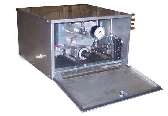
Figure 1
2B. SHUT-OFF
1. Turn “ON/OFF KNOB” clockwise until reaching stop
(“PILOT” position).
2. Press down slightly and continue turning clockwise from
“PILOT” position to the “OFF” position.
3. Turn off gas supply.
C. HEAT PIPE INSTRUCTION
Integral to the operation of the THERMAL SUPERCONDUCTOR
are the heat pipes supplied with the unit. When exposed to the CAUTION. The back of the absorption plate reaches
radiant heat from the Cata-Dyne™ they will provide enough energy temperature in excess of 300°F and the heat pipe
to maintain an enclosure temperature of 20°C with an outside
CAUTION
surface reaches 250°F. DO NOT, under any
ambient temperature of -40°C. circumstance, touch the heat pipe when the equipment
is in operation.
1. The Superconductor has been supplied with heat pipes
to conduct the heat generated from the heater into a
2. Mount the instrument panel thermostat bulb within the
separate enclosure. The face of the heater is mounted
enclosure, preferably centered vertically in the cabinet.
approximately 1/4” from the absorption plate of the
Once the heater is well established, set the instrument
heat pipes. Insert the heat pipes into the instrument
cabinet thermostat dial to #2 Allow Heater to stabilize for
enclosure as far as practical. Ideally, the side of the
approximately 1 hour. Make sure sufficient heat is being
Superconductor enclosure should be installed (bolted
generated to maintain catalytic reaction. Final thermostat
through) the side of the instrument cabinet as illustrated in
setting needs to be established by trial and error
Fig. 1.
depending on application. Position “1” is the minimum and
Bolt holes need to be field drilled into the instrument position “7” is the maximum temperature setting.
cabinet and Superconductor enclosure. Ensure that any
3. Set heat pipe thermostat dial to maximum when starting
portion of the heat pipe not in the enclosure or at the
heater. Change dial setting on heat pipe thermostat to
face of the heater is insulated, preferably with ceramic
midpoint after allowing the system to stabilize for at least
insulation. Apply a bead of outdoor rated silicone as shown
one hour. Final heat pipe thermostat settings needs to be
in Figure 1 for weather protection.
established by trial and error depending on application.
Shut-Off \ Heat Pipe Instruction
3NOTES NOTES
Catalytic Heater
Applications
Installation, Operation, & Maintenance Instructions

  FM                       WARNING. Improper installation adjustment, alteration,
                           excessive vibration, service, or maintenance can cause
 APPROVED
                WARNING    property damage, injury or death. Read the installation,
                           operating and maintenance instructions thoroughly before
                           installation or servicing this equipment.

              Special Notes
              The following special notices highlight important information in the
              installation and maintenance sections. Each serves a special purpose
              and is displayed in the format shown:

                          This symbol indicates a potentially hazardous situation, which,
                          if not avoided, can result in personal injury or damage to the
               CAUTION
                           equipment.

                          This symbol indicates a potentially hazardous situation, which,
              CAUTION
                          if not avoided, may be a shock hazard.

   ISO 9001
                          This symbol indicates an imminently hazardous situation,
                          which, if not avoided, could result in death or serious injury.
               WARNING

                                                                                   Part No. M20724-008.Rev.6.05   Feb 2018   Printed in Canada
TABLE OF CONTENTS
A. Certification & Intended Use 3
A.1 Certification .............................................................................................................3
A.2 Intended Use ...........................................................................................................3
B. Specifications 3
B.1 MKII Model (Series X) ...............................................................................................3
B.2 BX Model (Series G) ................................................................................................3
B.3 WX Model (Series X) ................................................................................................4
B.4 WXS Model (Series X) ..............................................................................................4
B.5 BX Model (Series X and G) ......................................................................................4
C. Installation 5
C.1 Clearances ..............................................................................................................5
C.2 Fuels .......................................................................................................................5
C.3 Piping ......................................................................................................................5
C.4 Electrical..................................................................................................................6
C.5 Ventilation ................................................................................................................6
D. Operation 7
D.1 Start-up ...................................................................................................................7
D.2 Shut Down ..............................................................................................................7
D.3 Multi-Heater Start-up...............................................................................................7
E. 12V Hazardous Electrical Installations 7
F. Space & Spot Heating 8
F.1 Space Heating ..........................................................................................................8
F.2 Spot Heating ............................................................................................................8
G. Cleaning & Personal Safety 8
G.1 Cleaning ..................................................................................................................8
G.2 Personal Safety .......................................................................................................8
H. Repairs 9
I. Ordering Information 9
J. Troubleshooting 10A. CERTIFICATION & INTENDED USE
A.1 Certification 4. The Model BX (Series G) Cata-Dyne™ heater is certified by
CSA and FM for use in general industrial non-hazardous
1. Model WX (Series X) & MKII (Series X) Cata-Dyne™ locations. Models listed are certified for industrial use only,
explosion-proof, flameless infrared catalytic gas heaters for either natural gas or propane gas.
are certified by the Canadian Standards Association (CSA)
for use in Class I, Divisions 1 and 2, Group D hazardous 5. CSA approved models are equipped for high altitudes:
locations temperature code T2C, at a maximum ambient 0 to 4500 ft (0 m to 1370 m) above sea level. FM approved
temperature of 40ºC (104ºF). models are equipped for high altitudes: 0 to 6000 ft (0 m to
1829 m) above sea level.
2. Model WXS (Series X) is FM certified for Class I, Division I,
Group D, temperature code T2B at a maximum ambient
temperature of 40°C (104°F). Model BX (Series X) and A.2 Intended Use
Model MKII (Series X) are FM certified for Class I, Division I,
The Cata-Dyne™ heater can be used in all industrial indoor
Group D, temperature code T2C at a maximum ambient
locations where a source of infrared radiant heat is required, where
temperature of 40°C (104°F).
adequate ventilation is available.
3. Models WX (Series X) are certified CE for use in gas
environments, Category 2, Zone 1 & 2, Group IIA.
B. SPECIFICATIONS
To ensure the maximum efficiency of your Cata-Dyne™ heater, B.2 BX Model (Series G)*
it should be installed with the heating surface positioned plus
or minus 45° from the vertical plane at a height of no more than CSA approved for use in general industrial non-hazardous locations.
8 ft (2.44 m). All heaters must be installed in accordance with the
Table 3 – BX Model (Series G)
latest revisions of the codes described in Table 1, page 3
and in accordance with any local codes and regulations. Before Input Ratings
installing the heater, all information on the heater nameplate must For Both Natural and Propane Gas
be carefully reviewed. The nameplate lists all the fuel and electrical Model Number
Max. Btu/hr Max. kW
requirements for the heater.
LPG NAT LPG NAT
Table 1 – National Code Requirements BX 6x6 1,250 1,500 0.366 0.439
For Cata-Dyne Heaters Installed in:
TM BX 6x12 2,500 3,000 0.732 0.879
Canada USA Internationally BX 6x24 5,000 6,000 1.464 1.757
- CSA/CAN-C22.1-02 - NFPA 70, National - Install according to BX 8x8 2,222 2,667 0.651 0.781
Canadian Electrical Electrical Code local and national/
Code international fuel BX 10x12 4,167 5,000 1.220 1.464
- NFPA 54, National
and electrical BX 12x12 5,000 6,000 1.464 1.757
- CSA/CAN-B149.1 Fuel Gas Code
codes
Natural Gas and BX 12x24 10,000 12,000 2.929 3.514
Propane Installation
Code BX 12x36 15,000 18,000 4.393 5.272
BX 12x48 20,000 24,000 5.857 7.029
BX 12x60 25,000 30,000 7.322 8.786 Certification & Intended Use and Specifications
B.1 MKII Model (Series X)
BX 12x72 30,000 36,000 8.786 10.543
CSA and FM approved for use in Class I, Division 1 and 2, Group D
hazardous (classified) locations, T-Code T2C. BX 18x24 15,000 18,000 4.393 5.272
BX 18x30 18,750 22,500 5.491 6.590
Table 2 – MKII Model (Series X)
BX 18x36 22,500 27,000 6.590 7.908
Input Ratings BX 18x48 30,000 36,000 8.786 10.543
Model Number For Both Natural and Propane Gas
BX 18x60 37,500 45,000 10.983 13.179
Max. Btu/hr Max. kW
BX 18x72 45,000 54,000 13.179 15.815
MKII 12x12 5,000 1.464
BX 24x24 20,000 24,000 5.857 7.029
MKII 12x24 10,000 2.929
BX 24x30 25,000 30,000 7.322 7.322
MKII 18x24 15,000 4.393
BX 24x36 30,000 36,000 8.786 10.543
MKII 18x48 30,000 8.786
BX 24x48 40,000 48,000 11.715 14.058
MKII 24x24 20,000 5.857
BX 24x60 50,000 60,000 14.644 17.572
MKII 24x48 40,000 11.715
*Model available for CSA only. 3B.3 WX Model (Series X) B.5 BX Model (Series X and G)**
CSA and FM approved for use in Class I, Division 1 and 2, Group D Series X: FM approved for use in Class I, Division 1, Group D
hazardous (classified) locations, T-Code T2C. hazardous (classified) locations, T-Code T2C.
Series G: Approved for general industrial non-hazardous locations
Table 4 – WX Model (Series X)
by FM.
Input Ratings
Table 6 – BX Model (Series X and G)
Model Number For Both Natural and Propane Gas
Max. Btu/hr Max. kW Input Ratings
Model Number For Both Natural and Propane Gas
WX 6x6 1,250 0.366
WX 6x12 2,500 0.732 Max. Btu/hr Max. kW
WX 6x24 5,000 1.464 BX 6x6 1,500 0.439
WX 6x60 12,500 3.661 BX 6x12 3,000 0.879
WX 8x8 2,222 0.651 BX 6x24 6,000 1.757
WX 10x12 4,167 1.220 BX 8x8 2,667 0.781
WX 12x12 5,000 1.464 BX 10x12 5,000 1.464
WX 12x24 10,000 2.929
BX 12x12 6,000 1.757
WX 12x36 15,000 4.393
BX 12x24 12,000 3.514
WX 12x48 20,000 5.857
BX 12x36 18,000 5.272
WX 12x60 25,000 7.322
BX 12x48 24,000 7.029
WX 12x72 30,000 8.786
BX 12x60 30,000 8.786
WX 18x24 15,000 4.393
WX 18x30 18,750 5.491 BX 12x72 36,000 10.543
WX 18x36 22,500 6.590 BX 18x24 18,000 5.272
WX 18x48 30,000 8.786 BX 18x30 22,500 6.590
WX 18x60 37,500 10.983 BX 18x36 27,000 7.908
WX 18x72 45,000 13.179 BX 18x48 36,000 10.543
WX 24x24 20,000 5.857 BX 18x60 45,000 13.179
WX 24x30 25,000 7.322 BX 18x72 54,000 15.815
WX 24x36 30,000 8.786
BX 24x24 24,000 7.029
WX 24x48 40,000 11.715
BX 24x30 30,000 7.322
WX 24x60 50,000 14.644
BX 24x36 36,000 10.543
WX 24x72 60,000 17.572
BX 24x48 48,000 14.058
BX 24x60 60,000 17.572
B.4 WXS Model (Series X)**
BX 24x72 72,000 21.087
FM approved for use in Class I, Division 1, Group D hazardous
(classified) locations, T-Code T2B.
Table 5 – WXS Model (Series X)
Input Ratings
Model Number For Both Natural and Propane Gas
Max. Btu/hr Max. kW
WXS 6x6 1,750 0.513
WXS 6x12 3,500 1.025
WXS 6x24 7,000 2.050
WXS 8x8 3,111 0.911 **Model available for FM only.
WXS 10x12 5,833 1.709
WXS 12x12 7,000 2.050
WXS 12x24 14,000 4.101
WXS 12x36 21.000 6.151
WXS 12x48 28,000 8.201
Specifications
WXS 24x24 28,000 8.201
WXS 24x36 42,000 12.302
WXS 24x48 56,000 16.402
WXS08 2,500 0.732
Round
WXS12 5,500 1.611
4C. INSTALLATION
C.1 Clearances Table 10 – C: Side (Heater Clearance)
Appropriate clearances from the heating surface must be observed Radiant
during the installation of the Cata-Dyne™ heaters (Figure 1 and Surface All Heaters Up to 60,000 Btu/hr (17.572 kW)
Tables 7 – 10, page 5). Maintain nameplate clearances from
Position
combustible materials such as wood, cloth, paper, etc. if the
heater is to be installed overhead maintain clearances as stated in Vertical (0°)
Figure 1 and Tables 7 – 10, page 5 from vehicles parked below.
0–45° up 12 305
A 0–45°
down
NOTE: Maintain nameplate clearances from combustible materials
C such as wood, cloth, paper, as well as any vehicles parked
in the area of the heater.
C.2 Fuels
D
1. The Cata-Dyne™ flameless gas heater is designed to
C
operate on clean, dry natural gas, or propane as specified
on the heater nameplate.
B
2. Natural Gas - these heaters are designed to use natural
Figure 1 – Heater Clearance gas (1,000 Btu/ft3, 37 MJ/m3) at 7" w.c. (1.73 kPa), 4.5" w.c.
(1.12 kPa) or 3.5" w.c. (0.86 kPa).
Table 7 – A: Top (Heater Clearance) 3. Propane - these heaters are designed to use propane gas
(2,500 Btu/ft3, 92 MJ/m3) at 11" w.c. (2.72 kPa).
Up to 12,000 12,000 to 48,000 Over 48,000
Radiant Btu/hr Btu/hr Btu/hr
Surface (3.514 kW) (14.058 kW) (17.572 kW) C.3 Piping
Position 1. A main shut-off valve must be installed upstream of all
in mm in mm in mm
auxiliary heater controls.
Vertical (0°) 18 457 18 457 42 1067
2. The ASV375 100% safety shut-off valve (SSOV) and
0–45° up 18 457 32 813 54 1372 appliance regulator (natural gas heaters only) can be
0–45° installed in the horizontal or vertical position. Older model
18 457 18 457 18 457
down heaters with the H17 safety shut-off valve must be installed
in the upright position (horizontally) only.
Table 8 – B: Bottom (Heater Clearance)
3. The thermostatic temperature controller can be installed in
Up to 12,000 12,000 to 48,000 Over 48,000 the horizontal or vertical position.
Radiant Btu/hr Btu/hr Btu/hr 4. The maximum inlet pressure to the 100% safety shut-
Surface (3.514 kW) (14.058 kW) (17.572 kW) off valve (SSOV), thermostatic temperature control and
Position appliance regulator is 1/2 psi (3.4 kPa). If the inlet pressure
in mm in mm in mm
is higher than this, a low pressure service regulator must be
Vertical (0°) 7 178 12 305 18 457 installed upstream of these components.
0–45° up 0 0 12 305 18 457 5. The maximum inlet pressure to the low pressure service
regulator (available from Thermon Heating Systems) is
0–45°
22 559 24 610 42 1067 250 psi (1.7 MPa). If the inlet pressure is higher than this, a
down
high-pressure regulator must be installed upstream.
Table 9 – D: Radiant Surface (Heater Clearance) For inlet pressues less than 25 psi (0.17 MPA) an alternate
Up to 12,000 12,000 to 48,000 Over 48,000 service regulator may have to be supplied. Contact
Radiant Thermon Heating Systems for recommendations on low
Btu/hr Btu/hr Btu/hr
pressure gas installations.
Surface (3.514 kW) (14.058 kW) (17.572 kW)
Position 6. For installation, see Figure 2, page 6 for typical
in mm in mm in mm Cata-Dyne™ Heater and Figure 3, page 6 for natural gas
Installation
MKII model.
Vertical (0°)
0–45° up 28 711 42 1067 60 1524 NOTE: Gas appliance regulators and manual shut-off valves
0–45° are required standard components for all CSA approved
down heaters; they are available as optional accessories for FM
approved heaters
5Ensure Bus Bar arrangement Ensure Bus Bar arrangement
Temperature sensing bulb
TEMPERATURE
corresponds with diagram corresponds with diagram
SENSING BULB
Thermostatic
temperature
THERMOSTATIC TEMPERATURE
CONTROLLER
ELECTRICAL
Electrical junction box
JUNCTION BOX
controller
Appliance regulator (natural
APPLIANCE REGULATOR
gas only)
(NATURAL GAS ONLY)
Thermocouple
THERMOCOUPLE ASSEMBLY
assembly Shut-off valve
SHUT-OFF VALVE
Tee to other heaters
TEE TO OTHER HEATERS
Safety shut-off
SAFETY valve
SHUT-OFF VALVE
Service regulator
SERVICE REGULATOR
Cata-DyneTM
CATA-DYNE™ HEATER
heater Flo-Dri
FLODRI FILTER
Ground Ground
filter
Connection Connection
Shut-off
valveSHUT-OFF VALVE
Figure 4 – Elements in parallel Figure 5 – Elements in series
C.5 Ventilation
NOTES:
REV. REVISION DESCRIPTION DATE BY
Figure 2 – Typical natural gas Cata-Dyne™ Heater
1) MATERIAL:
installation
TYPICAL NATURAL GAS INSTALLATION TITLE: 1. The catalytic reaction in Cata-Dyne™ heaters occurs when
2) ALL DIMENSIONS IN INCHES.
DWG NO.: 01-01-0110
SYTELINE NO.: N/A
SHEET:
±
TOLERANCE UNLESS NOTED OTHERWISE
1/2°
ANGULAR
± 0.005"
DECIMAL
± 1/16"
FRACTIONAL
natural gas or propane reacts with oxygen to produce
± 1 mm
METRIC
water vapor, carbon dioxide and infrared energy. Ventilation
SCALE: SCALE
DRN BY: nsanchez 02 Oct 2006
CHK'D BY:
Safety shut-off
SAFETY valve
SHUT-OFF VALVE
Temperature
TEMPERATURE
APP'D. BY: sensing
SENSING BULB bulb EDMONTON, ALBERTA
must be provided to allow adequate supply of oxygen for
Thermostatic
the reaction.
THERMOSTATIC TEMPERATURE CONTROLLER
temperature controller
Appliance
APPLIANCE regulator
REGULATOR
2. For every 1.0 ft2 (0.093 m²) of heater surface, 50 ft³/
(naturalGAS
(NATURAL gasONLY)
only)
hr (1.42 m³/hr) of air supply is required. For example, a
Shut-offVALVE
valve
SHUT-OFF
WX 24 x 24 heater (20,000 Btu/hr / 5.857 kW) would require
TeeTOtoOTHER
otherHEATERS
heaters
200 ft³/hr (5.66 m³/hr) of air to ensure proper operation of
TEE
ServiceREGULATOR
SERVICE regulator
the Cata-Dyne™ heater. See Table 11, page 6 for air
Flo-Dri
FLODRI FILTER
filter requirements.
Shut-off 3. To reduce the carbon dioxide and water vapor
Cata-Dyne
CATA-DYNE™ TM
HEATER
valveVALVE
heater
SHUT-OFF
concentrations in the building, a vent hood assembly can
be installed to provide positive ventilation from the heater
Thermocouple assembly
THERMOCOUPLE ASSEMBLY
(Figure 6, page 6).
ELECTRICAL
Electrical junction box
JUNCTION BOX
3" Pipe 3"Snow
3” Snowcap cap
3” Pipe
3"3” Elbow
Elbow
Figure 3 – Typical natural gas installation (MKII model only)
15"15”approx.
approx.
C.4 Electrical Vent 3” Flashing
3" Flashing
hood
NOTE: Ensure that the heater is not operational in an excessive
vibration environment or premature failure of the heater
may occur. Wall mounting bracket
Heater
1. All wiring is to be installed in accordance with the latest revisions
of the Canadian Electrical Code (CEC)/National Electrical Code Wall
11.5"
(NEC) and any applicable local codes. 11.5”
Dependant upon
2. It is desirable to install an indicating light on all starting application
systems. This will reduce the possibility of the power being
left on once the heater is started, which can severely reduce
the lifespan of the heater. Figure 6 – Ventilation from heater
3. Ground connections for 120V and higher voltage heaters are
Table 11 – Ventilation from heater
required as indicated in Figures 4 and 5, page 6.
4. The number of terminals in the junction box can be two Cu. Ft/hr of air per
Cu. M of air per Square
or four depending on the number of elements used in the Heater Series Square Ft of Heater
Meter of Heater surface
Surface
fabrication of the heater. All MKII models incorporate a
single element and therefore have only two terminals. The WX/MKII (CSA/FM) 50 15.3
connection procedure for the different combinations is as BX (CSA) 50 15.3
Installation
described in Figures 4 and 5, page 6. BX (FM) 60 18.3
WXS (FM) 70 21.3
CAUTION. Install MKII Series heaters with controls on
sides or bottom of heater ONLY.
CAUTION
6D. OPERATION
All Cata-Dyne™ heaters are supplied with a safety shut-off valve/ the original position and internally open the valve and allow
Thermocouple assembly to ensure the safe operation of the heater. gas to flow to the heater. If the valve does not stay open when
Under no circumstances should the reset button be held or locked the reset button is released, it may be necessary to wait an
into the depressed position by use of a mechanical restraint. additional few minutes and then depress the reset button
A tamper resistant model safety shut-off valve is available if desired. again. This will allow the electrical elements additional time to
warm up.
D.1 Start-up 7. When the catalytic reaction is well established, turn off the
electrical power to the elements, and wait for an additional
1. Ensure the heater has been installed according to all
amount of time.
instructions and relevant codes.
8. If the heater is equipped with a thermostatic temperature
2. Turn on the main gas supply to the system.
controller, it can be set to the desired setting after the
3. If the heater is equipped with a low-flow thermostatic catalytic reaction has been established for at least one hour.
temperature controller (capable of flow capacities below
30,000 Btu/hr), rotate the dial completely clockwise to the
D.2 Shut Down
fully open position.
Turn off the gas supply to the heater.
4. If the heater is equipped with a high-flow thermostatic
temperature controller (capable of flow capacities above
30,000 Btu/hr), rotate the dial completely counterclockwise to D.3 Multi-Heater Start-up
the fully open position.
Cata-Dyne™ heaters can also be purchased/installed in multi-heater
5. Turn on the power to the electrical elements. assemblies. If these assemblies are 12V, each heater must be
6. After 15 – 20 minutes, depress the reset button on the top of started individually. This ensures the correct voltage and current will
the 100% safety shut-off valve. The button should return to be reaching the heater from the power supply.
E. 12V HAZARDOUS ELECTRICAL INSTALLATIONS
Most oil and gas production buildings have an area classification
as follows:
1. Class I, Division 1 (Zone 1), within the building. Refer to
Figures 7 and 8, page 7.
2. Class I, Division 2 (Zone 2), up to 10 ft (3 m) from the
building in any direction. Refer to Figures 7 and 8,
page 7.
10 ft. 15 ft.
3.0 m 4.6 m 3. Class I, Division 2 (Zone 2), between 10 ft (3 m) and 25 ft
18 in.
0.46 m
(7.6 m) from the building in all directions at an elevation of
Vehicle located outside 18" (0.45 m) above the ground. Refer to Figures 7 and 8,
hazardous area
page 7
Figure 7 – Vehicle location 4. Connection to the power supply must be outside of the
Class I, Division 2 location (Figure 9, page 7). All electrical
apparatus and wiring within this area must conform to the
Operation and 12V Hazardous Installations
appropriate codes.
Building wall
Standard
battery cable CATA-DYNETM
heater c/w
10 ft. 15 ft explosion-proof
3.0 m 4.6 m + _ junction box
OUTSIDE BUILDING - Class I Division 2
area use appropriate electrical fittings
INSIDE BUILDING -
25 ft. Seal Class I Division 1 area use
7.6 m appropriate electrical fittings
Class I, Division 1 (Zone 1) Class I, Division 2 (Zone2)
2)
Class I Class I Division 2 (Zone
Division 1 (Zone 1) 18 in. (0.46 m) above ground. Figure 9 – Power supply connector (see Caution below).
Class I, Division 2 (Zone 2) 18 in.Subject
(0.46 tom)possible
above transient
ground vapour.
Class I Subject to possible
Division 2 (Zone 2) transient vapour CAUTION. Connect battery outside 25 ft (7.6 m) in
Figure 8 – Classes and Figure divisions non-hazardous area.
CAUTION 7F. SPACE & SPOT HEATING
F.1 Space Heating 8. Make sure the piping is large enough to handle the gas load
(refer to the sample Piping Calculation in the Cata-Dyne™
1. A separate heat load calculation should be done for each catalog for sizing information).
building in which a Cata-Dyne™ heater will be installed for
space heating purposes. 9. Make sure the electrical starting system has sufficient
current carrying capacity and conforms to all applicable
2. The heat load calculation determines the building heat electrical codes.
losses through the structure and allows for air infiltration. For
sample Heat Load Calculation, visit: www.cata-dyne.com. 10. It is advisable to install an indicator light in the electrical
circuit to reduce the possibility of the power being left on
3. Cata-Dyne™ heaters produce low intensity infrared heat that once the heater is started.
is absorbed by objects within the range of the heat source.
The closer the object is to the source of heat the more
heat the object will absorb. Cata-Dyne™ heaters should F.2 Spot Heating
be placed close to the floor level within the building to heat
1. There are several factors to consider when Cata-Dyne™
objects close to the floor.
heaters are utilized for spot heating.
4. Ideally, Cata-Dyne™ heaters should be mounted 1 ft to 3 ft
2. Infrared energy travels in straight lines from the face of the
(0.3 m to 1 m) from the floor and equally spaced around the
Cata-Dyne™ heater covering approximately 160° of an arc
building perimeter for space heating applications.
and is inversely proportional to the square of the distance.
5. If low mounting is not practical, then overhead mounting The heater should therefore be mounted as close as practical
may be utilized. Overhead mounted heaters should be to the object requiring heat for maximum temperature rise. A
sloped face down to a maximum 45° angle to direct the minimum of 28" (710 mm).
infrared energy towards the floor. Overhead mounting should
3. Match the shape of the object requiring heat with the
be restricted to heaters of 30,000 Btu/hr (8.8 kW) capacity
appropriate Cata-Dyne™ heater, e.g. WX/BX 6x24 for long
and larger.
narrow objects or WX/BX 12x12 for a square object.
6. If the building requires only one heater, place the
4. Objects requiring heat should be painted dull, dark colors for
Cata-Dyne™ heater as close as possible to the center of the
maximum infrared absorption and objects not requiring heat
longest wall.
should be painted light or reflective colors.
7. For multiple heater installations, space the Cata-Dyne™
5. Insulate and protect plastic, rubber and similar materials
heaters as evenly as possible around the perimeter of
from direct intense infrared heat.
the building.
G. CLEANING & PERSONAL SAFETY
G.1 Cleaning
The Cata-Dyne™ heater box may be cleaned but only once it has
Space & Spot Heating and Cleaning & Personal Safety
been allowed to cool. If your Cata-Dyne™ catalytic pad (white pad)
is dirty it should never be contacted in order to avoid damaging it.
This means that it should not be wiped down, sprayed with water
or blown with compressed air. Any contact with the catalytic pad
may damage the surface requiring the owner to return the unit to
the factory for repair.
G.2 Personal Safety
The Cata-Dyne™ heater does not produce harmful carbon
monoxide gas when used with natural gas or propane. Adequate
ventilation must be incorporated in any building design to ensure
oxygen replenishment and removal of any carbon dioxide.
Protective grills should be used on any installation where personnel
may come in contact with the face of the heater.
8H. REPAIRS
If the Cata-Dyne™ heater malfunctions, and is no longer operating,
send the heater to the factory for servicing. Do not attempt to
service the unit.
When returning the heater you can fill out the online repair form at
http://www.ccithermal.com/online-repair-form.php or include the
following information with the heater when shipping:
1. Company name and address
2. Contact name
3. Telephone/fax number/email
4. Product model and serial numbers
5. Tagging codes
6. Advise if an estimate is required prior to starting the repair
7. P.O. Number
8. Description of problem(s) and/or required repairs
9. Special instructions (if applicable)
10. Return shipping instructions
I. ORDERING INFORMATION
1. Quote requests can be made using our Online RFQ e. Company name and contact
process found at: www.cata-dyne.com
f. Billing address and phone number
2. Order any of Thermon Heating Systems’ products by
g. Shipping instructions
telephone, fax, mail, e-mail, or on-line at:
www.cata-dyne.com h. Special tagging instructions
3. To assist us in processing your order as quickly and i. Date required
efficiently as possible, please provide us with the following
j. Method of payment:
information:
i. On account: P.O. number required
a. Cata-Dyne™ product name
i. Cata-Dyne™ model number ii. Credit card: VISA or Mastercard number
b. Fuel gas: natural gas or propane iii. Cash or cheque
c. Starting voltage: 12, 24, 120, 208, 240, 480, or 600
d. Accessories required:
i. Protection Grill
Repairs and Ordering Information
ii. Wall Mount Brackets
iii. Thermostat
iv. Regulator
v. Start Up Leads (12V system only)
vi. Vent Hood
vii. Other
9J. TROUBLESHOOTING
1. Ensure that the fuel matches that listed on the nameplate. 9. Cata-Dyne™ heaters are designed to use clean fuel and
to be used in non-contaminated atmospheres. Sulphur
2. Ensure that the voltage matches that listed on the nameplate.
compounds in the fuel or atmosphere will poison the catalyst
3. Check for any physical damage. All signs of physical bed over a period of time and render the heater inoperative.
damage to the catalyst pad such as holes, tears or a general If the heater has been exposed to sulphur compounds, it
deterioration of the catalyst bed indicate that it is time to should be sent to the factory for service.
have the heater repaired. Excessive vibration may cause
10. Avoid spraying the face of the heater with high-pressure air,
damage to the inner catalysts structure which may cause
steam or water because this can damage the catalyst bed,
premature failure.
if physical damage is visible, return the heater to the factory
4. Check the gas supply pressure at the heater – 7" w.c. for servicing.
(1.73 kPa), 4.5" w.c. (1.12 kPa) or 3.5" w.c. (0.86 kPa) for
11. Ensure that the thermostat is correct for the model size, fuel,
natural gas and 11" w.c. (2.72 kPa) for propane.
and pressure specifications for the heater it is fitted to. If the
5. Check the gas orifice for obstructions or dirt and ensure thermostat is too low, the heater will not have sufficient fuel
the size matches that listed on the nameplate. It may rating to operate and will stop.
be necessary to install a filter upstream of the heater or
regulator if the gas supply is dirty. If the fuel supply is
constantly dirty and/or wet it would be advisable to use
bottled propane fuel.
6. Check the mounting position of the heater. The face of the
heater should be preferably in the vertical position and
should not vary more than 45° from the vertical position for
maximum efficiency.
7. Check for saturation of the catalyst face caused by
condensation or rain running down the face of the heater.
If the heater has been exposed to water, it is advisable to
place the unit in a warm area for a period of a few hours or
longer if required. Once the moisture is removed, the heater
can be re-installed and re-started.
8. Check the start-up leads cable size to ensure that the
resistance of the cable is not reducing the current to the
heater. This would not allow sufficient power to the electrical
element to preheat the catalyst to the activity temperature. It
is recommended to run the service vehicle at fast idle while
starting the heater.
Troubleshooting
10NOTES
PLEASE ADHERE TO INSTRUCTIONS IN THIS MANUAL
                                                                       Failure to do so may be dangerous and may void certain provisions
                                                                       of your warranty.

For further assistance, please call 24hr hotline: 1.800.661.8529 (U.S.A. and Canada)
Please have model and serial numbers available before calling.

WARRANTY: Under normal use the Company warrants to                     No warranty applies to paint finishes except for manufacturing defects
the purchaser that defects in material or workmanship will be          apparent within 30 days from the date of installation.
repaired or replaced without charge for a period of 18 months          The Company neither assumes nor authorizes any person to assume for it
from date of shipment, or 12 months from the start date of             any other obligation or liability in connection with the product(s).
operation, whichever expires first. Any claim for warranty must
                                                                       The Purchaser agrees that all warranty work required after the initial
be reported to the sales office where the product was purchased
                                                                       commissioning of the product will be provided only if the Company
for authorized repair or replacement within the terms of this
                                                                       has been paid by the Purchaser in full accordance with the terms and
warranty.
                                                                       conditions of the contract.
Subject to State or Provincial law to the contrary, the Company
                                                                       The Purchaser agrees that the Company makes no warranty or
will not be responsible for any expense for installation, removal
                                                                       guarantee, express, implied or statutory, (including any warranty of
from service, transportation, or damages of any type whatsoever,
                                                                       merchantability or warranty of fitness for a particular purpose) written
including damages arising from lack of use, business interruptions,
                                                                       or oral, of the Article or incidental labour, except as is expressed or
or incidental or consequential damages.
                                                                       contained in the agreement herein.
The Company cannot anticipate or control the conditions of
product usage and therefore accepts no responsibility for              LIABILITY: Technical data contained in the catalog or on the
the safe application and suitability of its products when used         website is subject to change without notice. The Company reserves
alone or in combination with other products. Tests for the             the right to make dimensional and other design changes as required.
safe application and suitability of the products are the sole          The Purchaser acknowledges the Company shall not be obligated
responsibility of the user.                                            to modify those articles manufactured before the formulation of the
                                                                       changes in design or improvements of the products by the Company.
This warranty will be void if, in the judgment of the Company,
the damage, failure or defect is the result of:                        The Company shall not be liable to compensate or indemnify the
                                                                       Purchaser, end user or any other party against any actions, claims,
•    Vibration, radiation, erosion, corrosion, process
                                                                       liabilities, injury, loss, loss of use, loss of business, damages, indirect
     contamination, abnormal process conditions, temperature
                                                                       or consequential damages, demands, penalties, fines, expenses
     and pressures, unusual surges or pulsation, fouling,
                                                                       (including legal expenses), costs, obligations and causes of action of
     ordinary wear and tear, lack of maintenance, incorrectly
                                                                       any kind arising wholly or partly from negligence or omission of the
     applied utilities such as voltage, air, gas, water, and others
                                                                       user or the misuse, incorrect application, unsafe application, incorrect
     or any combination of the aforementioned causes not
                                                                       storage and handling, incorrect installation, lack of maintenance,
     specifically allowed for in the design conditions or,
                                                                       improper maintenance or improper operation of products furnished
•    Any act or omission by the Purchaser, its agents, servants        by the Company.
     or independent contractors which for greater certainty, but
     not so as to limit the generality of the foregoing, includes
     physical, chemical or mechanical abuse, accident,
     improper installation of the product, improper storage
     and handling of the product, improper application or the
     misalignment of parts.

    Edmonton                                Oakville                  Orillia                     Houston                     Denver
    1-780-466-3178                          1-800-410-3131            1-877-325-3473              1-855-219-2101              1-855-244-3128
    F 780-468-5904                          1-905-829-4422            1-705-325-3473              1-281-506-2310              1-303-979-7339
    5918 Roper Road                         F 905-829-4430            F 705-325-2106              F 281-506-2316              F 303-979-7350
    Alberta, Canada T6B 3E1
MC
Applications pour le
radiateur catalytique
Instructions d’installation et d’utilisation
FM AVERTISSEMENT. Une modification ou une altération
inadéquate de l’installation, des vibrations excessives, un
APPROVED
AVERTISSEMENT entretien mal effectué ou une réparation inappropriée peuvent
causer des dommages matériels, des blessures ou la mort.
Lire attentivement les instructions d’installation, d’utilisation et
d’entretien avant d’installer ou d’entretenir l’équipement.
Remarques particulières
Les avertissements particuliers suivants attirent l’attention sur des renseignements
importants dans les sections concernant l’installation et l’entretien. Chacun répond
à une situation particulière et est illustré comme suit:
Ce symbole indique une situation potentiellement dangereuse
pouvant provoquer des blessures corporelles ou des dommages à
ATTENTION
l’équipement si elle ne peut pas être évitée.
Ce symbole indique une situation potentiellement dangereuse pouvant
AVERTISSEMENT présenter un danger d’électrocution si elle ne peut pas être évitée.
ISO 9001
Ce symbole indique une situation potentiellement dangereuse
pouvant provoquer la mort ou des blessures graves si elle ne peut
AVERTISSEMENT
pas être évitée.
Part Numéro. M20724-008.Rev.6.05 fev 2018 Imprimé au CanadaTABLE DES MATIÈRES
A. Homologation et utilisation prévue 15
A.1 Homologation ........................................................................................................15
A.2 Usage prévu ..........................................................................................................15
B. Spécifications 15
B.1 Modèle MKII (série X) .............................................................................................15
B.2 Modèle BX (série G) ...............................................................................................15
B.3 Modèle WX (série X) ..............................................................................................16
B.4 Modèle WXS (série X) ...........................................................................................16
B.5 Modèle BX (séries X et G) ......................................................................................16
C. Installation 17
C.1 Distances de dégagement .....................................................................................17
C.2 Combustibles ........................................................................................................17
C.3 Tuyauterie ..............................................................................................................17
C.4 Électricité...............................................................................................................18
C.5 Ventilation ..............................................................................................................18
D. Fonctionnement 19
D.1 Mise en marche .....................................................................................................19
D.2 Mise hors tension ..................................................................................................19
D.3 Mise en marche de plusieurs radiateurs ................................................................19
E. Installations électriques 12 V dangereuses 20
F. Chauffage de l’espace et localisé 21
F.1 Chauffage de l’espace ............................................................................................21
F.2 Chauffage localisé ..................................................................................................21
G. Nettoyage et protection personnelle 21
G.1 Nettoyage ..............................................................................................................21
G.2 Protection personnelle ..........................................................................................21
H. Réparations 23
I. Renseignements pour les commandes 23
J. DépannageA. HOMOLOGATION ET UTILISATION PRÉVUE
A.1 Homologation 4. Le radiateur Cata-DyneMC modèle BX (série G) est homologué
CSA et approuvé FM pour une utilisation dans des
1. Les radiateurs catalytiques infrarouges au gaz sans flamme emplacements industriels généraux ne présentant pas de
antidéflagrants des modèles WX (série X) et MKII (série X) de danger. Les modèles présentés sont homologués pour une
Cata-DyneMC sont homologués par l’Association canadienne utilisation industrielle uniquement, soit avec du gaz naturel ou
de normalisation (CSA) pour une utilisation dans des du gaz propane.
emplacements classifiés dangereux de classe I, divisions 1
et 2, groupe D, code de température T2C, à une température 5. Les modèles homologués CSA sont équipés pour être utilisés
ambiante de 40°C (104°F). à de hautes altitudes: 0 à 4500 pi (0 à 1370 m) au-dessus du
niveau de la mer. Les modèles approuvés FM sont équipés
2. Le modèle WXS (série X) est approuvé FM pour la classe I, pour être utilisés à de hautes altitudes: 0 à 6000 pi (0 à
division 1, groupe D et le code de température T2B à une 1829 m) au-dessus du niveau de la mer.
température ambiante maximale de 40°C (104°F). Le modèle
BX (série X) et le modèle MKII (série X) sont approuvés FM
pour la classe I, division I, groupe D et le code de température A.2 Usage prévu
T2C à une température ambiante maximale de 40°C (104°F).
Le radiateur Cata-DyneMC peut être utilisé dans tous les sites
3. Les modèles WX (série X) sont certifiés CE pour une utilisation industriels intérieurs où une source de chaleur radiante infrarouge est
dans des atmosphères contenant des gaz, catégorie 2, requise, lorsqu’une ventilation adéquate est disponible.
zones 1 et 2, groupe IIA.
B. SPÉCIFICATIONS
Afin d’assurer l’efficacité maximale de votre radiateur Cata-DyneMC, B.2 Modèle BX (série G)*
celui-ci devrait être installé de manière à ce que la surface de
chauffage soit positionnée selon un angle de plus ou moins Homologué CSA pour une utilisation dans des emplacements
45 degrés par rapport au plan vertical et à une hauteur maximale de industriels généraux ne présentant pas de danger.
8 pi (2,44 m). Tous les radiateurs doivent être installés conformément
Table 3 – Modèle BX (série G)
à la version la plus récente des codes décrits dans le Tableau 1,
page 15 et conformément à tous les codes et règlements locaux. Spécifications
Il est nécessaire d’examiner attentivement tous les renseignements pour le gaz naturel et le gaz propane
Numéro de
contenus sur la plaque signalétique avant d’installer le radiateur. La
modèle Btu/h max. kW max.
plaque signalétique énumère toutes les exigences du radiateur en
matière de combustible et d’électricité. LPG NAT LPG NAT
BX 6x6 1,250 1,500 0.366 0.439
Tableau 1 – Exigences du Code national
BX 6x12 2,500 3,000 0.732 0.879
Pour les radiateurs Cata-DyneMC installés: BX 6x24 5,000 6,000 1.464 1.757
au Canada aux États-Unis à travers le monde BX 8x8 2,222 2,667 0.651 0.781
- CSA/CAN-C22.1-02, - 70, National - l’équipement BX 10x12 4,167 5,000 1.220 1.464
Code canadien de Electrical Code conformément BX 12x12 5,000 6,000 1.464 1.757
l’électricité NFPA aux codes locaux,
BX 12x24 10,000 12,000 2.929 3.514
nationaux et
Homologation et utilisation prévue / Spécifications
- CSA/CAN-B149.1, Code - 54, National
internationaux sur BX 12x36 15,000 18,000 4.393 5.272
d’installation du gaz Fuel Gas Code
les combustibles et
naturel et du propane BX 12x48 20,000 24,000 5.857 7.029
l’électricité
BX 12x60 25,000 30,000 7.322 8.786
B.1 Modèle MKII (série X) BX 12x72 30,000 36,000 8.786 10.543
BX 18x24 15,000 18,000 4.393 5.272
Homologué CSA et FM pour une utilisation dans des emplacements
BX 18x30 18,750 22,500 5.491 6.590
dangereux (classifiés) de classe I, divisions 1 et 2, groupe D,
BX 18x36 22,500 27,000 6.590 7.908
Code T T2C.
BX 18x48 30,000 36,000 8.786 10.543
Tableau 2 – Modèle MKII (série X) BX 18x60 37,500 45,000 10.983 13.179
Spécifications BX 18x72 45,000 54,000 13.179 15.815
Numéro de BX 24x24 20,000 24,000 5.857 7.029
pour le gaz naturel et le gaz propane
modèle BX 24x30 25,000 30,000 7.322 7.322
Btu/h max. kW max.
BX 24x36 30,000 36,000 8.786 10.543
MKII 12x12 5,000 1.464
BX 24x48 40,000 48,000 11.715 14.058
MKII 12x24 10,000 2.929
BX 24x60 50,000 60,000 14.644 17.572
MKII 18x24 15,000 4.393
MKII 18x48 30,000 8.786 *Modèle homologué CSA seulement
MKII 24x24 20,000 5.857
15
MKII 24x48 40,000 11.715B.3 Modèle WX (série X) B.5 Modèle BX (séries X et G)**
Homologué CSA et FM pour une utilisation dans des Série X : Approuvé FM pour une utilisation dans des emplacements
emplacements dangereux (classifiés) de classe I, divisions 1 et 2, dangereux (classifiés) de classe I, division 1, groupe D, Code T T2C.
groupe D, Code T2C.
Série G : Approuvé FM pour les emplacements industriels
généraux ne présentant pas de danger.
Tableau 4 – Modèle WX (série X)
Spécifications
Tableau 6 – Modèle BX (séries X et G)
Numéro de pour le gaz naturel et le gaz propane Spécifications
modèle Numéro de
Btu/h max. kW max. pour le gaz naturel et le gaz propane
modèle
WX 6x6 1,250 0.366 Btu/h max. kW max.
WX 6x12 2,500 0.732 BX 6x6 1,500 0.439
WX 6x24 5,000 1.464 BX 6x12 3,000 0.879
WX 6x60 12,500 3.661 BX 6x24 6,000 1.757
WX 8x8 2,222 0.651 BX 8x8 2,667 0.781
WX 10x12 4,167 1.220 BX 10x12 5,000 1.464
WX 12x12 5,000 1.464 BX 12x12 6,000 1.757
WX 12x24 10,000 2.929
BX 12x24 12,000 3.514
WX 12x36 15,000 4.393
BX 12x36 18,000 5.272
WX 12x48 20,000 5.857
BX 12x48 24,000 7.029
WX 12x60 25,000 7.322
BX 12x60 30,000 8.786
WX 12x72 30,000 8.786
BX 12x72 36,000 10.543
WX 18x24 15,000 4.393
BX 18x24 18,000 5.272
WX 18x30 18,750 5.491
WX 18x36 22,500 6.590 BX 18x30 22,500 6.590
WX 18x48 30,000 8.786 BX 18x36 27,000 7.908
WX 18x60 37,500 10.983 BX 18x48 36,000 10.543
WX 18x72 45,000 13.179 BX 18x60 45,000 13.179
WX 24x24 20,000 5.857 BX 18x72 54,000 15.815
WX 24x30 25,000 7.322 BX 24x24 24,000 7.029
WX 24x36 30,000 8.786 BX 24x30 30,000 7.322
WX 24x48 40,000 11.715 BX 24x36 36,000 10.543
WX 24x60 50,000 14.644 BX 24x48 48,000 14.058
WX 24x72 60,000 17.572
BX 24x60 60,000 17.572
BX 24x72 72,000 21.087
B.4 Modèle WXS (série X)**
Homologué FM pour une utilisation dans des emplacements
dangereux (classifiés) de classe I, division 1, groupe D, Code T T2B.
Tableau 5 – Modèle WXS (série X)
Spécifications
Numéro de
pour le gaz naturel et le gaz propane **Modèle homologué FM seulement.
modèle
Btu/h max. kW max.
WXS 6x6 1,750 0.513
WXS 6x12 3,500 1.025
WXS 6x24 7,000 2.050
WXS 8x8 3,111 0.911
WXS 10x12 5,833 1.709
WXS 12x12 7,000 2.050
WXS 12x24 14,000 4.101
WXS 12x36 21.000 6.151
WXS 12x48 28,000 8.201
Spécifications
WXS 24x24 28,000 8.201
WXS 24x36 42,000 12.302
WXS 24x48 56,000 16.402
WXS08 2,500 0.732
Rond
WXS12 5,500 1.611
16C. INSTALLATION
C.1 Distances de dégagement Tableau 10 – C: Side (dégagement du radiateur)
Un dégagement approprié de la surface de chauffage doit être
Position de la Tous les radiateurs jusqu’à
respecté durant l’installation des radiateurs Cata-DyneMC (voir la surface radiante 60 000 BTU/h (17,572 kW)
Figure 1 et les Tableaux 7 – 10, page 17). Veiller à respecter
le dégagement mentionné sur la plaque signalétique pour les Vertical (0°)
matériaux comme le bois, les tissus, le papier, etc. Lorsque le 0 à 45°
radiateur doit être installé en hauteur, s’assurer de conserver le vers le haut 12 305
dégagement mentionné à la Figure 1 et dans les Tableaux 7 – 10, 0 à 45°
vers le bas
page 17 pour les véhicules stationnés en dessous.
Remarque: Veiller à respecter le dégagement mentionné sur la plaque
A signalétique pour les matériaux comme le bois, les tissus et le
papier ainsi que tout véhicule stationné à proximité du radiateur.
C C.2 Combustibles
1. Le radiateur au gaz sans flamme Cata-DyneMC est conçu
pour fonctionner avec du gaz naturel ou du gaz propane
propre et sec, comme indiqué sur la plaque signalétique
du radiateur.
D
C 2. Gaz naturel – ces radiateurs sont conçus pour utiliser du gaz
naturel (1 000 BTU/pi³, 37 MJ/m³) à une pression de 7 po CE
B
(1,73 kPa), 4,5 po CE (1,12 kPa) ou 3,5 po CE (0,86 kPa).
Figure 1 – Dégagement du radiateur 3. Propane – ces radiateurs sont conçus pour utiliser du gaz
propane (2 500 BTU/pi³, 92 MJ/m³) à 11 po CE (2,72 kPa).
Tableau 7 – A: Haut (dégagement du radiateur)
C.3 Tuyauterie
Position Jusqu’à 12 000 12 000 à 48 000 Plus de 48 000
de la BTU/h BTU/h BTU/h 1. Une vanne d’arrêt doit être installée en amont de tout
surface (3,514 kW) (14,058 kW) (17,572 kW) dispositif auxiliaire de contrôle du radiateur.
radiante po mm po mm po mm 2. La vanne de sécurité à arrêt complet (SSOV) ASV375
et le régulateur de l’appareil (radiateurs au gaz naturel
Vertical (0°) 18 457 42 1067
uniquement) peuvent être installés en position horizontale
0 à 45° ou verticale. Les plus anciens modèles de radiateurs avec la
18 457 32 813 54 1372
vers le haut
vanne d’arrêt de sécurité H17 doivent être installés debout
0 à 45°
18 457 18 457 (horizontalement) SEULEMENT.
vers le bas
3. Le dispositif d’ajustement de la température thermostatique
Tableau 8 – B: Bottom (dégagement du radiateur) peut être installé en position horizontale ou verticale.
Position Jusqu’à 12 000 12 000 à 48 000 Plus de 48 000 4. La pression maximale d’entrée de la vanne de sécurité
de la BTU/h BTU/h BTU/h à arrêt complet (SSOV), du dispositif d’ajustement de la
surface (3,514 kW) (14,058 kW) (17,572 kW) température thermostatique et du régulateur de l’appareil est
radiante po mm po mm po mm de 1/2 psi (3,4 kPa). Si la pression d’entrée est supérieure
à cette valeur, un régulateur de service basse pression doit
Vertical (0°) 7 178 12 305 18 457 être installé en amont de ces composants.
0 à 45°
vers le haut
0 0 12 305 18 457 5. La pression d’entrée maximale du régulateur de service
0 à 45°
basse pression (disponible chez Thermon Heating Systems
22 559 24 610 42 1067 est de 250 psi (1,7 MPa). Si la pression d’entrée est supérieure
vers le bas
à cette valeur, un régulateur de haute pression doit être
Tableau 9 – D: Surface radiante (dégagement du radiateur) installé en amont.
Jusqu’à 12 000 12 000 à 48 000 Plus de 48 000 Lorsque la pression d’entrée est inférieure à 25 psi
Position (0,17 MPa), un régulateur de service de rechange pourrait
BTU/h BTU/h BTU/h
de la
(3,514 kW) (14,058 kW) (17,572 kW) devoir être fourni. Communiquer avec Thermon Heating
surface
Systems pour obtenir des recommandations sur les
radiante po mm po mm po mm
installations à gas à faible pression.
Vertical (0°) 6. Pour l’installation, voir la Figure 2, page 18 pour le
Installation
0 à 45° radiateur Cata-DyneMC typique et la Figure 3, page 18
vers le haut 28 711 42 1067 60 1524
pour le modèle MKII au gaz naturel.
0 à 45°
vers le bas Remarque: Les régulateurs de gaz de l’appareil et les vannes d’arrêt manuel
sont des composants standards requis pour tous les radiateurs
homologués CSA; ce sont des accessoires offerts en option avec
les radiateurs approuvés FM Installation typique d’un radiateur 17
Cata-DyneMC au gaz naturel.Ampoule sensible à la température
TEMPERATURE
SENSING BULB
ATTENTION. Installer les radiateurs de la série MKII
de manière à ce que le dispositif de commande se
Dispositif
d’ajustement de
THERMOSTATIC TEMPERATURE
ATTENTION trouve sur les côtés ou la partie inférieure du
Boîte de jonction électrique
ELECTRICAL
la température
CONTROLLER
thermostatique
JUNCTION BOX
Régulateur de l’appareil (gaz
radiateur UNIQUEMENT.
APPLIANCE REGULATOR
naturel uniquement
(NATURAL GAS ONLY)
Ensemble
THERMOCOUPLE ASSEMBLY Robinet d’arrêt
SHUT-OFF VALVE
S’assurer que la disposition de S’assurer que la disposition de
thermocouple
Raccord en T vers les
TEE TO OTHER HEATERS la barre omnibus correspond la barre omnibus correspond
Vanne d’arrêt autres radiateurs au diagramme. au diagramme.
SAFETYde sécurité
SHUT-OFF VALVE
Régulateur de
SERVICE REGULATOR
Radiateur
CATA-DYNE™ HEATER
l’approvisionnement
Cata-DyneMC
Filtre
FLODRI FILTER
Flo-Dri
Robinet
d’arrêtSHUT-OFF VALVE
Mises à la terre Mises à la terre
NOTES:
Figure 2 – Installation typique d’un radiateur Cata-Dyne
1) MATERIAL:
MC
au
TYPICAL NATURAL GAS INSTALLATION
REV.
TITLE:
REVISION DESCRIPTION DATE BY
gaz naturel
2) ALL DIMENSIONS IN INCHES.
01-01-0110 DWG NO.: SHEET:
Figure 4 – Éléments en parallèle
TOLERANCE UNLESS NOTED OTHERWISE Figure 5 – Éléments en série
± 1/2° ± 0.005" ± 1/16" ± 1 mm
SYTELINE NO.: N/A ANGULAR DECIMAL FRACTIONAL METRIC
SCALE: SCALE
02 Oct 2006
C.5 Ventilation
DRN BY: nsanchez
CHK'D BY:
Ampoule sensible
TEMPERATURE à la
SENSING BULB
APP'D. BY: température EDMONTON, ALBERTA
Vanne d’arrêt de sécurité
SAFETY SHUT-OFF VALVE
Dispositif d’ajustement de la
1. La réaction catalytique dans les radiateurs Cata-DyneMC
THERMOSTATIC TEMPERATURE CONTROLLER
température thermostatique se produit lorsque le gaz naturel ou le gaz propane réagit
Régulateur de l’appareil
APPLIANCE REGULATOR
(gaz naturel
(NATURAL uniquement
GAS ONLY) avec l’oxygène pour produire de la vapeur d’eau, du gaz
RobinetVALVE
SHUT-OFF d’arrêt carbonique et de l’énergie infrarouge. Une ventilation doit
Raccord en T vers les
TEE TO OTHER HEATERS
autres radiateurs être fournie pour assurer un apport d’oxygène adéquat afin
de permettre à la réaction de se produire.
SERVICE REGULATOR
Régulateur de
l’approvisionnement
Filtre
FLODRI FILTER
Flo-Dri
2. Pour chaque 1,0 pi² (0,093 m²) de surface du radiateur,
50 pi³/h (1,42 m³/h) d’air sont requis. Par exemple, un
Robinet
Radiateur
CATA-DYNE™ HEATER
d’arrêtVALVE
SHUT-OFF radiateur WX 24 x 24 (20 000 BTU/h ou 5 857 kW)
Cata-Dyne MC
nécessiterait 200 pi³/h (5,66 m³/h) d’air pour fonctionner
adéquatement. Voir le Tableau 11, page 18 pour connaître
Ensemble thermocouple
THERMOCOUPLE ASSEMBLY
ELECTRICAL
Boîte de jonction
JUNCTION BOX
les exigences en matière d’approvisionnement en air.
électrique
3. Afin de diminuer les concentrations en dioxyde de carbone
et en vapeur d’eau dans le bâtiment, un assemblage de hotte
Figure 3 –– Installation au gaz naturel typique (modèle MKII
uniquement) de ventilation peut être installé afin de fournir une ventilation à
pression positive à partir du radiateur (Figure 6, page 18).
C.4 Électricité 3" Tuyau 3"Snow
3” Bouchon
cap de neige
3” Pipe
3"3” Elbow
Coude
Remarque: Ensure that the heater is not operational in an excessive vibration
environment or premature failure of the heater may occur.
Hotte de
1. Le câblage doit être installé conformément à la plus récente 15” approx.
15" env. ventilation
3” Flashing
version du Code canadien de l’électricité (CCE) et du Code 3" Solin
national de l’électricité (CNE) aussi qu’à tout code local
en vigueur.
2. Il est souhaitable d’installer un voyant lumineux sur tous les Support pour
Radiateur montage mural
systèmes de mise en marche. Ceci permet de diminuer le
risque de les laisser sous tension après que le radiateur ait
Bâtiment
été mis en marche, ce qui peut gravement diminuer la durée 11.5"
11.5”
de vie de l’appareil. Selon l’utilisation
3. Des mises à la terre sont requises pour les radiateurs
utilisant un voltage de 120 V et plus, comme illustré aux
Figures 4 et 5, page 18.
4. Deux ou quatre bornes peuvent être requises dans la boîte Figure 6 – Ventilation à partir du radiateur
de jonction, selon le nombre d’éléments utilisés dans la
Tableau 11 – Ventilation à partir du radiateur
fabrication du radiateur. Tous les modèles MKII intègrent
Installation
un seul élément et, par conséquent, ne contiennent que pi³/h d’air par pi² de m³ d’air par m² de surface
deux bornes. Les procédés de branchement pour les Heater Series
surface du radiateur du radiateur
différentes combinaisons sont illustrés dans les Figures 4 et 5, WX/MKII (CSA/FM) 50 15.3
page 18. BX (CSA) 50 15.3
BX (FM) 60 18.3
18 WXS (FM) 70 21.3You can also read