Guidelines for Low Emission and High Efficiency Stove Concepts
←
→
Page content transcription
If your browser does not render page correctly, please read the page content below
Guidelines for Low Emission
 and High Efficiency Stove Concepts

Authors:
Robert Mack and Hans Hartmann
Technology and Support Centre in the Centre of Excellence for Renewable Resources
(TFZ), Straubing, Germany

Christoph Mandl and Ingwald Obernberger
BIOS BIOENERGIESYSTEME GmbH, Austria

Ingmar Schüßler
RISE Research Institutes of Sweden AB, Sweden

Johan Furborg
NIBE AB, Sweden

Florian Volz
Kutzner + Weber GmbH, Germany

 Report within the scope of the ERA-NET Bioenergy Project “WoodStoves2020” –
 Development of Next Generation and Clean Wood Stoves
 July 2017
ERA-NET Bioenergy Project WoodStoves2020
 Guidelines for Low Emission and High Efficiency Stove Concepts
 Disclaimer
The concepts and design guidelines presented are a result of a scientific project. The
implementation and utilisation of the research results is the decision of each individual
person/company. The authors undertake no liability for the utilisation and implementation of
the research work and research results as well as for consequences of the resulting
technology development or plant operation.

Contact:
Technology and Support Centre in the Centre of Excellence for Renewable Resources (TFZ)
Schulgasse 18, D-94315 Straubing, Germany
Email: bkinfo@tfz.bayern.de, Tel.: +49 9421 300-110

Download of Guidelines: http://www.tfz.bayern.de/en/162907/index.php
ERA-NET Bioenergy Project WoodStoves2020 Guidelines for Low Emission and High Efficiency Stove Concepts Preface ERA-NET Bioenergy is a network of national research and development programmes focusing on bioenergy which includes 14 funding organisations from 10 European countries: Austria, Denmark, Finland, France, Germany, Ireland, The Netherlands, Poland, Sweden and the United Kingdom. Its mission is to enhance the quality and cost-effectiveness of European bioenergy research programmes, through coordination and cooperation between EU Member States. The project WoodStoves2020 (Development of next generation and clean wood stoves) has been supported in the period between April 2014 and June 2017 by ERA-NET Bioenergy under the 7th Joint Call for Research and Development of the ERA-NET Bioenergy from 2013. Today small-scale biomass combustion is one of the most relevant bioenergy applications. Driven by EU-wide and national measures to promote the utilisation of biomass for energy production, the European market for biomass based residential heating systems is expected to substantially increase by about 130 % until 2020 (based on 2009). Regarding the installed units stoves show the highest and steadily increasing numbers in Europe. According to market studies performed within the EU FP7 project EU-UltraLowDust (Project No. 268189), in 2020 in Europe a potential for an annual installation of almost 2,200,000 stoves (logwood and pellet stoves) was forecasted. This additional potential for renewable energy production will of course contribute to a reduction of the EU greenhouse gas emissions. However, it is also well known that among the different residential biomass combustion technologies logwood stoves show the highest CO, OGC and fine particulate matter (PM) emissions. Against this background, the project WoodStoves2020 aimed at the development of innovative measures and technologies in order to further reduce emissions from wood stoves, to increase their thermal efficiency and to expand their field of application from solely single room heating to central heating. The latter could especially be of relevance for future applications in low energy buildings. Accordingly, the detailed objectives of the project had been structured as follows. Objectives related to emission reduction: Development and implementation of automated control systems for stoves as a feature of new stoves but also as retrofit units for existing models. Automated control systems can help to widely eliminate user induced operation errors and therefore have a huge potential for emission reduction. Evaluation and test of new high-temperature catalysts specially adapted to wood stoves for efficient CO, OGC and soot emission reduction. Catalysts should be implemented in new stove concepts as a basis for an ultra-low emission operation which could be comparable to the emission level of automated small-scale boilers. Evaluation and test of foam ceramic materials for efficient PM emission reduction. Evaluation of the implementation of modern chimney draught regulators.
ERA-NET Bioenergy Project WoodStoves2020 Guidelines for Low Emission and High Efficiency Stove Concepts Objectives related to increasing efficiency and new fields of application: Development and evaluation of efficient and novel heat storage options for stoves such as the application of PCM (phase change material) with high heat storage potential. Investigations regarding efficient heat recovery from stoves (increase of efficiency by the implementation of heat storage units or measures to stabilise the draft or to reduce standing losses). Objectives related to the implementation and evaluation of the different measures: Test of the most promising concepts by performing test runs with prototypes. Development of design guidelines for stove manufacturers based on the evaluation of the new technologies tested towards a clean stove technology for 2020. Development of guidelines for the implementation and retrofit of selected measures for old stoves. With the new technologies developed within the project an emission reduction between 50 and 80 % and an increase of the efficiencies in a range above 90 % shall be possible. If in future all newly installed wood stoves in Europe would be equipped with these new technologies, a PM emission reduction of 60 to 90 % could be achieved. In order to reach these objectives, a consortium of 4 research organisations and 4 industrial partners from 4 European countries collaborated within WoodSoves2020 (see next page). This document summarises the outcomes of the investigations regarding the improvement of wood stoves regarding emissions and efficiency. It should support stove manufacturers concerning the optimisation of their products and the development and design of new products. The recommendations given were worked out based on scientific investigations and comprehensive test runs.
ERA-NET Bioenergy Project WoodStoves2020
 Guidelines for Low Emission and High Efficiency Stove Concepts
WoodStoves2020 project partners
Project coordinator:

 Technology and Support Centre in the Centre of
 Excellence for Renewable Resources (TFZ)
 Straubing, Germany

Further RTD partners:

 BIOS BIOENERGIESYSTEME GmbH
 Graz, Austria

 RISE Research Institutes of Sweden
 Built Environment / Energy and Circular Economy
 Borås, Sweden

Industrial partners

 RIKA Innovative Ofentechnik GmbH
 Micheldorf, Austria

 Kutzner + Weber GmbH
 Maisach, Germany

 Nibe AB,
 Markaryd, Sweden
ERA-NET Bioenergy Project WoodStoves2020
 Guidelines for Low Emission and High Efficiency Stove Concepts
Table of contents
1 Introduction and objectives ............................................................................................ 1
2 Definitions and limitations .............................................................................................. 1
 2.1 Definition of chimney stoves ...................................................................................... 1
 2.2 Limitations ................................................................................................................. 2
3 Basic definitions and stove functioning .......................................................................... 2
4 General requirements for low emission and highly efficient log wood stoves ................. 4
 4.1 Requirements for low emissions ................................................................................ 4
 4.2 Requirements for high efficiency ................................................................................ 6
5 Geometric design concept ............................................................................................. 9
6 Automatic combustion control .......................................................................................12
7 CFD-aided design of wood stoves ................................................................................12
8 Utilization of integrated catalysts and foam ceramics ....................................................14
 8.1 Stove catalysts..........................................................................................................15
 8.2 Utilization of integrated high temperature catalysts ...................................................16
 8.3 The non-catalytic foam ceramic elements in log wood stoves ...................................17
9 Avoidance of standing losses from hot and cold chimney .............................................17
10 Stove connection to the chimney ..................................................................................19
11 Recommendations regarding user documentation ........................................................20
12 Acknowledgements.......................................................................................................23
13 Related literature ..........................................................................................................23
1 ERA-NET Bioenergy Project WoodStoves2020 Guidelines for Low Emission and High Efficiency Stove Concepts 1 Introduction and objectives Chimney stoves are one of the most common appliances used for residential heating around Europe. Apart from their use for heating purposes, stoves are also seen as decorative accessories, and therefore a broad range of different designs is available. But combustion of biomass produces air pollutant emissions such as carbon monoxide (CO), organic gaseous carbon (OGC), oxides of nitrogen (NOX) and particulate matter. Furthermore, in state-of-the-art stoves no automatic combustion control systems are applied, which means user-induced errors, that negatively influence emissions, are more likely to happen. Therefore, further development and optimisation of stoves by means of primary measures is necessary in order to achieve low emissions, which will meet given and planed stricter emission limits (e.g. Ecodesign directive) without cost intensive secondary measures (e.g. filters) as well as to increase their efficiency. Within the scope of the ERA-NET BIOENERGY project “WoodStoves2020” primary measures for lowering emissions in wood stoves were evaluated by comparison with results from former projects and literature. In addition, test runs investigating the effect of implementing high- and medium temperature catalysts as well as foam ceramics were performed. Furthermore, new stove design concepts were created, which also covered innovative combustion air control systems. Some stoves investigated were also operated using existing retrofit temperature based devices for combustion air control in order to assess the possible improvements. These direct research outcomes as well as the existing knowledge background were used as the basis for the recommendations in this guideline. Target group. This guideline provides information primarily for stove developers and manufacturers to use the presented design concepts for development of low-emission and highly efficient appliances. Furthermore, the report should also be of interest for researchers, policy makers and authorities. 2 Definitions and limitations 2.1 Definition of chimney stoves The following features apply to a chimney stove (Figure 1). It is a free standing room heater, not walled, and usually with a front window. Only a relatively small amount of heat storage is possible due to the low mass of the stove, but storage devices could be added to the stove to increase its efficiency. Fuel is charged in a single layer onto the bed of embers. Therefore: frequent re-charging is required. Heat is released by radiation from the window and other surfaces and by convection via air ducts and outlets.
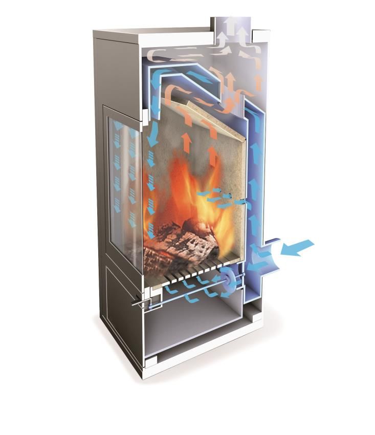
2 ERA-NET Bioenergy Project WoodStoves2020 Guidelines for Low Emission and High Efficiency Stove Concepts Figure 1: Examples of chimney stoves (from left to right: Contura, Rika, HWAM A/S). (Source: from each manufacturer) 2.2 Limitations Much of the technical information in this Guideline also applies to slow heat releasing stoves (e. g. tiled stove inserts, closed fire place inserts), but such stoves are not the main focus in this document. This is due to the high variation of their designs and features which would make it difficult to give generalized recommendations. Consequently, tiled stoves, open fire places, cooking stoves, all stoves with water jackets, pellet stoves and sauna stoves are not covered in this guideline. Apart from all questions concerning proper stove design and operation, further technical improvements are also possible, e. g. by an automated process control or improvement of the heat exchanger. But such secondary measures are separately presented in other guidelines which were also prepared within this ERA-NET-project (see [1], [2]). 3 Basic definitions and stove functioning For better understanding the following definitions apply. Primary air – It provides the oxygen needed to gasify the wood fuel and to burn the remaining char in the ember. Primary air is directed to the space where the solid fuel is pyrolysed (bed of embers). Secondary air – It is needed to provide oxygen to be mixed with released pyrolysis gases which burn as visible flames. Window purge air – It flushes the window to keep the glass clean. It also acts as combustion air (partly primary and secondary). Main combustion chamber – space where the fuel is gasified and where the majority of the combustion take place (digit 5 in Figure 2). The main combustion chamber can be divided into different sections: fuel zone and secondary combustion zone
3 ERA-NET Bioenergy Project WoodStoves2020
Guidelines for Low Emission and High Efficiency Stove Concepts
Post combustion chamber – space provided for combustion gases and particles to
burn out sufficiently (digit 7 in Figure 2)
Secondary combustion – combustion of the gasification products and intermediate
products
PM1 – particulate matter below 1 µm (aerodynamic diameter), corresponding
definitions for PM2.5 and PM10
TSP – total suspended particulates
OGC – organic gaseous carbon
Description of stove functioning
In the following, a typical design and functioning principle of a modern log wood stove is
described. This functioning is illustrated by the schematic description of a room heater for
firewood ("chimney stove") given in Figure 2.
Modern stoves usually have a central air inlet socket (1). For installations where the
combustion air is taken from the heated room itself, this central air inlet socket is not
required. But it is recommended to provide the possibility of using a retrofit air flow control
flap and it is definitely required, if a full shut-down of the stove after heating shall be
performed. The latter is to prevent standing losses from cold and hot chimneys (see Chapter
9). For air tight buildings it is required that a combustion air conduit (pipe) can be connected
to the chimney stove via a central air inlet socket (1). Such an air inlet socket can also enable
the retrofitting of an electronic combustion air control system via a motor driven flap.
The combustion air flow into the chimney stove (blue arrows Figure 2) is divided into
a primary air stream (2) which flows through the grate into the combustion chamber
and
a window purge air flow (3) which is conducted to the window top and is then directed
through nozzles or slots downwards along the window. It flushes the window to
prevent tar, soot or particle depositions. But it also serves as combustion air. One
part of it usually reaches the bed of embers and can provide primary air to the wood
fuel if either the grate is closed (e. g. by a rotation rosette) or if the grate air damper is
locked or if no grate exists at all. Another part of this air stream is directed above the
bed of embers into the combustion chamber (5) to provide oxygen for the gas phase
combustion (serves as secondary air).
Some modern stoves are equipped with an additional secondary air inlet at the back
of the stove wall (4) (this air flow is sometimes also called "tertiary air"). Such an inlet
improves the turbulent mixture of oxygen with the pyrolysis gases released from the
solid fuel. The portion of this air stream is usually smaller than the window purge air.
The heat produced in the main-combustion chamber is conserved by a heat resistant mineral
insulation layer made of fire clay, chamotte or vermiculite. This ensures high temperatures
for complete combustion.4 ERA-NET Bioenergy Project WoodStoves2020 Guidelines for Low Emission and High Efficiency Stove Concepts In the post-combustion chamber (7) combustion is completed, therefore high temperatures are still maintained by refractory lining (fire clay, chamotte or vermiculite insulation). Also high turbulence is achieved through the deflection plate or "baffle" (6) which leads the hot gases to the narrow entrance of the post combustion chamber. The gases are here finally burnt out and conducted to the flue gas socket from where they exit to the chimney (8) via a connecting pipe. In the upper area of the stove the hot flue gases heat cast iron, steel or mineral stove surfaces to relatively high temperatures of up to 200 °C. Even higher temperatures are achieved on the window surface which contributes strongly to the heat release into the room. Another relevant heating effect is generated by convection which is created by air flow from ground level passing upwards along the stove surfaces or through convection canals in the stove. Flue gas socket (8) Post-combustion chamber (7) Baffle (6) Window purge air (3) Main-combustion chamber (5) Secondary air (4) Combustion air supply (1) Flue gas Combustion air Primary air (2) Figure 2: A schematic description of a typical chimney stove (Source: TFZ [4]) 4 General requirements for low emission and highly efficient log wood stoves 4.1 Requirements for low emissions The particulate emissions can be divided into coarse mode (particles > 1 µm aerodynamic diameter) and fine mode particles (particles
5 ERA-NET Bioenergy Project WoodStoves2020 Guidelines for Low Emission and High Efficiency Stove Concepts the gas velocities in the combustion chamber and the subsequent ducts and turning chambers: Long ducts with many bends retain more particles. High primary air flow releases more coarse particles from the grate. Fine particulate matter emissions consist of soot, fine fly ash (inorganic compounds) and organic matter. Soot (elemental carbon) is formed in the flame in regions with lack of oxygen or on cold walls. Fine fly ash is formed by vaporization and subsequent nucleation/condensation of inorganic vapours released from the fuel during combustion. Particulate organic matter is a result of incomplete oxidation of combustion gases that condense onto particles or form own particles. TSP includes both fine and coarse particles. The relevant gaseous pollutants are organic gaseous carbon (OGC), carbon monoxide (CO) and nitrogen oxides (NOX). The NOX emissions from wood log combustion are fuel derived, and therefore the amount of NOX is determined by the nitrogen content of the fuel. Organic gaseous carbon is released from the fuel during gasification. The amount of OGC in the flue gas is affected by the completeness of combustion. Carbon monoxide is an intermediate product from the oxidation of carbonaceous material. Generally the efficiency of combustion (temperature and mixture with combustion air) affects the amount of CO. During the burn-out phase (i. e. after flame extinction) the formation of CO is more difficult to avoid due to low diffusivity of O2 into the char and because of relatively low temperatures in the combustion chamber. Adequate quantities of air should be provided for combustion, especially through the window purge air and the additional secondary air nozzles (if used in the design). It is also important to make sure that the appliance has sufficient chimney draft. Sufficient temperatures in the combustion chamber are needed to oxidize the gases which are released from the fuel bed. The temperature is affected by the refractory lining in the combustion chamber, the shape and size of the combustion chamber, the material and isolation of the door as well as the size of the window and the radiation coefficients of the glass. The combustion gases should have sufficient residence time in the combustion chamber. The residence time is affected by the gas volume flow and the distribution of the flue gas over the combustion chamber versus the size of the combustion chamber as well as the location of the additional secondary air nozzles (if used). The nozzles can be located for example in the back or in the side walls as well as at different heights. Sufficient mixing of air with the combustion gases is crucial in order to achieve complete combustion. Mixing is affected by several factors: The distribution of the window purge air in the combustion chamber The direction and geometry of the additional secondary air nozzles (if used) The velocities of flue gas and combustion air The distribution of air to the different air flows such as secondary air and window purge air (air staging)
6 ERA-NET Bioenergy Project WoodStoves2020 Guidelines for Low Emission and High Efficiency Stove Concepts The geometry of the main combustion and the post combustion chamber The geometry the deflection plate and the use of baffles in the post combustion chamber Avoid leakage air streams by using appropriate material for the door and ensure that the door seals correctly. Avoid short-circuiting of flue gas streams within the stove. There should be no gaps between the plate separating the main combustion chamber from the post combustion chamber and the side respectively back walls (see Figure 2), through which unburnt gases from the main combustion chamber could flow to the flue gas outlet without passing through the burnout zones in the main and the post combustion chamber. 4.2 Requirements for high efficiency Type testing efficiency. According to DIN EN 13240 [9] and the new prEN 16510 [5] (to be published) the efficiency of wood stoves is calculated from the losses during and after combustion (see equations (1) to (4) and Table 1). For untreated wood logs the losses from unburnt material (qc) on the grate are set to 0.5 %. = − ( + + ) (1) ∗ , ∗( − ) + = , , = ( − ) ∗ ( , ∗( + ) + , ∗ , ∗ ( )) (2) 100∗ − = , = 12644 ∗ ∗ 0,536∗( + (3) , 2 )∗100 ∗ ∗ ∗ = , = (4) ,
7 ERA-NET Bioenergy Project WoodStoves2020 Guidelines for Low Emission and High Efficiency Stove Concepts Table 1: Notations and units used in calculations Notation Definition Unit B Combustible constituents in residues referred to mass of residues % of mass Cf Carbon content of test fuel (as fired) % of mass CO Carbon monoxide content of the dry flue gases % of volume CO2 Carbon dioxide content of the dry flue gases % of volume Cr Carbon content of the residue, referred to the quantity of test fuel fired. % of mass (Approximation: Cr = A B / 100) (NOTE For wood logs where the carbon content in the ash residue is not measured and the heat loss qr is assumed to be equivalent to 0,5 % points of efficiency then Cr = 1,4925 10 Hi,f ) -5 3 Cp,fg Specific heat of dry flue gases in standard conditions, depending on kJ / K* m temperature and composition of the gases 3 Cp,fgw Specific heat of water vapour in flue gases in standard conditions, kJ / K* m depending on temperature Hf Hydrogen content of the test fuel (as fired) % of mass Hi,f Lower calorific value of the test fuel (as fired) kJ / kg Efficiency % Qa Thermal heat losses in the flue gases, referred to the unit of mass of the kJ/kg test fuel Qb Chemical heat losses in the flue gases, referred to the unit of mass of the kJ/kg test fuel Qc Heat losses through combustible constituents in the residue referred to kJ/kg the unit of mass of the test fuel (as fired) qa Proportion of losses through specific heat in the flue gases Qa, referred to % the calorific value in the test fuel (as fired) qb Proportion of losses through latent heat in the flue gases Qb, referred to % the calorific value in the test fuel (as fired) qc Proportion of heat losses through combustible constituents in the % residues Qc, referred to the calorific value of the test fuel A Residue passing through the grate, referred to the mass of the fired test % of mass fuel Tfg Flue gas temperature °C Ta Room temperature °C Wf Moisture content of the test fuel (as fired) % of mass With regard to improving efficiency, the chemical losses of the flue gas are usually insignificant. A relevant improvement on efficiency can usually be achieved by high CO2 concentration resp. low lambda values. Furthermore, the efficiency can be considerably improved by reducing the flue gas temperature at the flue gas socket. Figure 3 shows the theoretically possible improvement of the efficiency by increasing the CO2 concentration in the flue gas and also by lowering the flue gas temperature.
8 ERA-NET Bioenergy Project WoodStoves2020
Guidelines for Low Emission and High Efficiency Stove Concepts
Figure 3: Possible efficiency improvement by increasing the CO2-concentration in the
flue gas at constant flue gas temperatures. Assumptions: CO: 0.15vol-% d.b., Fuel: beech
wood, fuel moisture content: 14 wt-% w.b. (calculations according to equations 1 to 4).
To achieve lower flue gas temperatures at the flue gas socket and thus to increase
efficiency, the heat exchanger surfaces should be appropriately dimensioned in order to
ensure an efficient heat transfer.
System efficiency. The efficiency determination in type testing does not cover some
important parameters that impact the total system efficiency. At first, any heat release after
the temperature measuring location in the standard measuring is disregarded by definition.
On the other hand, the type test also disregards any heat losses after combustion ("standing
losses") which occur when the stove or chimney are still warm. These gains and losses can
significantly improve or reduce the overall efficiency of a fully integrated system. Therefore:
The stove manufacturer should provide respective guidance to the installer to ensure
that the connection to the chimney is made in an efficient way. For example it is in
most cases preferable to use the vertical flue outlet with a sufficiently long elbow pipe
for chimney connection instead of applying a short horizontal pipe from the rear flue
gas socket, which can be an optional connection for many stoves. The magnitude of
the possible efficiency gains by prolongation of the (vertical) connecting pipe is
described in Figure 8 (see Chapter 10).
Such efficiency gains can be counteracted by losses after combustion, caused by the
heat flow through the chimney which remains relatively high due to the draught
created by the heat stored in stove and chimney. The general order of magnitude and
the prevention of such standing losses by technical features of the stove are
described in Chapter 9.9 ERA-NET Bioenergy Project WoodStoves2020 Guidelines for Low Emission and High Efficiency Stove Concepts Also the losses from unburned material for modern stoves can be many times higher than the 0.5 % claimed in the standard. This applies particularly to the case when the stove shuts down the air supply automatically after heating operation in order to avoid standing losses. However, there are controversial opinions about whether such (coarse) charcoal residues shall be regarded a loss or shall rather be seen as fuel reserve when restarting the stove for a new heating cycle. 5 Geometric design concept This chapter presents those aspects that need to be considered in the geometric and material design of the stove. The stove should at least consist of a main combustion chamber and a post combustion chamber (or space for post combustion that can also be a duct). Insulating materials should be used in the main and post combustion chamber in order to keep the flue gas temperatures sufficiently high. Use appropriate insulation strategies for the side and back walls as well as the ceiling of the main combustion chamber, e. g. refractory bricks in combination with a layer of heat resistant mineral wool and a small air volume between insulation and the outer (steel) stove casing. Keep the window at a moderate size (see Figure 3) and use glass qualities for the window with low radiation coefficients. Also, the application of coated glasses and of double or triple glazed windows (with an air gap in between) is an option. Avoid direct heat transfer through metal sheets or the grate to the surroundings Figure 4: Example for a moderately sized window (left side) and a very large window surface (right side, not recommended) (Source: TFZ [4])
10 ERA-NET Bioenergy Project WoodStoves2020
 Guidelines for Low Emission and High Efficiency Stove Concepts
The flue gas temperature in the main and in the post combustion chamber should be high
and well distributed among the volume, whereas the fuel bed should be kept at moderate
temperatures to prevent excessively high burning rates.
Heat exchange. Downstream of the post combustion chamber the flue gas should have
enough time to efficiently cool down. Sufficiently large heat exchanging surfaces are needed
to maximize the efficiency of the appliance. Heat exchanging surfaces should be placed after
the post combustion chamber. The heat exchange to the room air can be improved by
introducing forced ventilation via a fan, if the stove is equipped with adequate air ducts or
exchange surfaces. Furthermore, additional heat exchangers can be connected downstream
of the stove. The simplest form of such a heat exchanger is the connecting pipe to the
chimney. The longer this pipe is the lower the flue gas temperature will be. Significant
efficiency gains can thus be achieved (see Figure 8 in Chapter 10).
Appliances with integrated heat storage units may show significantly increased efficiencies
and therefore also contribute to a better economy of stove technologies. Moreover, they
contribute to a better climate in the rooms as the energy released to the room can be better
distributed over a rather long period in comparison to state-of-the-art wood log stoves.
Modern heat storage concepts can also apply phase-change-materials (PCM) for delayed
and controlled heat provision. Further information about how such integration can be
performed, can be found in the "Guidelines for heat storage units based on Phase Change
Materials (PCM)" [2], which were also elaborated within this EraNet Project
"WoodStove2020".
In general, it is recommended that the bottom of the main combustion chamber is equipped
with a grate. This is to simplify de-ashing before the next use and to ensure a good
distribution of the primary air among the fuel bed. However, it must be guaranteed, that the
air flow through the grate can be shut down completely. Grate air flow is usually only suitable
during the first ignition phase and during the last batch after flame extinction (charcoal
burnout phase in a stove operation), or between flame extinction and recharging, when the
stove is using an automated process control.
Combustion chamber geometry. High and slim combustion chamber geometry (Figure 5) is
usually preferable compared to a wide and low height (although the smaller base area may
then require shorter wood logs). A high and slim shape improves flame dispersion and leads
to a more homogeneous residence pattern for the produced pyrolysis gases in the hot zones
(i.e. less danger of short circuit flows).
11 ERA-NET Bioenergy Project WoodStoves2020 Guidelines for Low Emission and High Efficiency Stove Concepts Figure 5: Example of a high and slim (left side) compared to a low and wide (right side, not recommended) combustion chamber geometry (Source: TFZ [4]) Air supply and air staging. Air staging is an efficient way of reducing the emissions in a chimney stove. Air staging means that different air flows are introduced to ensure equally distributed fuel decomposition and charcoal burnout as well as an almost complete gas phase burnout. Chimney stoves without air staging are usually operated with primary air only. Combustion air can be supplied as primary, window purge air and secondary air (for more comprehensive description see Chapter 3). A minimum requirement for air staging is to add primary air and window purge air. The air streams should be separately controlled. To avoid false operation the manual air control should be achieved by a single handle only. The best way to control it is an automatic air control system (see Chapter 6). If, besides to the window purge additional air secondary air is injected, it should not directly hit the logs. Usually, all air streams should be separately controllable. Other points that should be taken into account when designing air staging: The air streams that take part in secondary combustion should be pre-heated. This can be arranged without an external heating system by the design of the air ducts. In contrast, the primary air should not be pre-heated (but preferably delivered at ambient temperature) in order to avoid too fast burning rates. Due to limited chimney draught the pressure drops of the combustion air supply and flue gas canals have to be considered and to be kept low. Special care has to be taken regarding the position of additional secondary air nozzles (if considered). If they are mounted too low, the air stream can hit the wood logs and act as primary air. If they are mounted too high (at the upper end of the rear
12 ERA-NET Bioenergy Project WoodStoves2020 Guidelines for Low Emission and High Efficiency Stove Concepts wall in the main combustion chamber), their effect will be limited because then the effective residence time after mixing at high temperatures becomes shorter. It shall also be mentioned, that there is a conflict for those stoves which shall – perhaps additionally – be tested according the Norwegian standard test method NS 3058 – 3059 [6 – 8]. In this case the manufacturer is tempted to mount the rear nozzles higher than for those stoves that shall be tested according to Central European test method EN 13240 [9]. This higher position can be beneficial when performing the obligatory overloading test, but it is disadvantageous when an optimal stove operation is performed, as given in the Central European test method. 6 Automatic combustion control Reasons and benefits of an automated combustion control are listed as follows. Due to an optimised supply of combustion air over the duration of a batch the emissions can be minimized and the efficiency can be significantly increased. In addition to that an automated control system can prevent standing losses of a stove (see Chapter 9). Therefore, it will lead to fuel savings over the heating season. Moreover, an automatic control system will minimize the user influence (inaccurate air valve settings), and it can maximize the comfort for the user. The automated control system also opens up the possibility to provide feedback to the stove operator (e. g. by error messages on display or by acoustic and visual indications). This can for example be useful when ignition is not performed correctly or when fuel mass charging and fuel moisture content are inappropriate. Such feedback is more and more being regarded necessary to avoid false operation. For further information about combustion control systems, look at the “Guidelines for automated control systems for stoves” [1], which were also elaborated within this EraNet Project "WoodStove2020". 7 CFD-aided design of wood stoves BIOS BIOENERGIESYSTEME GmbH has developed a CFD model for the development and optimisation of biomass grate furnaces [13]. This tool consists of an in-house developed empirical fixed bed combustion model, which can also be applied for wood log combustion, as well as CFD models implemented in ANSYS / Fluent, which were especially adapted and validated for turbulent reactive flows in biomass combustion plants. For wood-log fired stoves, a time-dependent profile of wood log combustion is derived by the transformation of release profile along the grate calculated by the basic packed bed combustion model. Since a transient CFD simulation of the whole batch process is today still too time consuming, steady-state operating conditions have to be defined. In order to reduce a possible falsification of the CFD simulations by the heat storage properties of the stove, an energy balance around the stove as a function of time has to be performed based on test run
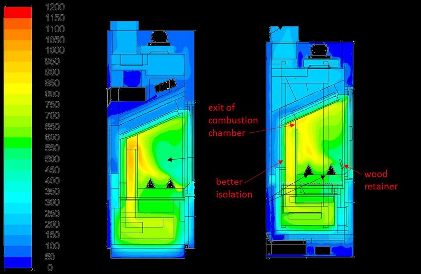
13 ERA-NET Bioenergy Project WoodStoves2020
 Guidelines for Low Emission and High Efficiency Stove Concepts
data. By this energy balance, two virtual steady-state operating points where the heat
storage of the stove is approximately zero can be estimated. The first of these states occurs
during the start-up phase and is not used for CFD simulations as the gradients in this phase
are rather large. For CFD simulation the second state, which occurs at about 2/3 of the batch
length is used.
For the simulation of the gas phase usually the Realizable k-ε Model for turbulence, the
Discrete Ordinates Model for radiation, as well as the Eddy Dissipation Concept (EDC) in
combination with a detailed chemical mechanism for Methane combustion (DRM22 with 22
species and 104 reactions) is applied.
With CFD simulation a number of relevant processes can be analysed: the flow of the
combustion air and the flue gas in the stove, the flow of the convective air in the air jacket of
the stove, gas phase combustion in the stove as well as heat transfer between gas phase
and stove material (insulation, sheets and glass windows). By these simulations, velocities
and temperatures of combustion air, convective air and flue gas, path lines of air and flue
gas, O2 and CO concentrations in the flue gas, material and surface temperatures of the
stove materials, as well as heat transfer, efficiency and pressure losses can be analysed.
Numerous applications showed, that the CFD-aided development and optimisation of wood-
log fired stoves leads to reduced emissions (CO and fine particulates), a better utilisation of
the stove volume as well as an enhanced plant efficiency. Furthermore, the CFD simulations
result in reduced development times, lower test efforts and an increased security during plant
development.
As an example, Figure 6 depicts iso-surfaces of temperatures in a wood log fired stove
before and after optimisation. In the basic variant, the flow in the combustion chamber was
not favourable concerning the mixing of the flue gas from the wood logs with the window
purge air. Furthermore, the volume of the combustion chamber was not fully utilized, which
leads to large temperature gradients. As countermeasures the implementation of a wood
retainer as well as a re-design of the exit of the combustion chamber were recommended.
Based on these recommendations, a first testing plant was realised. Further measures that
were implemented covered a better isolation on the back wall of the stove (leading to higher
temperatures and therefore improved burnout) and a symmetric design of the air supply
(leading to an evenly distributed flow in the combustion chamber, especially around the wood
logs, and therefore a stable flame).
Test runs at the modified stove showed that CO and particulate emissions could be
significantly reduced (by approximately 49 % relating to the first variant investigated).
Furthermore, the improved temperature distribution (less gradients) improved the efficiency
of the stove (an improvement by 52 % of the efficiency related to the heat-exchanger area
could be reached).
14 ERA-NET Bioenergy Project WoodStoves2020
 Guidelines for Low Emission and High Efficiency Stove Concepts

Figure 6: Iso surfaces of temperatures [°C] in a central vertical section of a stove
(Source: BIOS) Modifications: geometry of the exit of the combustion chamber; inclusion of a
wood retainer; improved air supply; improved isolation

Recently, CFD simulations have also been used in order to investigate wood stoves with
heat storage devices [2, 14]. Thus, it is possible to derive and discuss the thermal behaviour
of a heat storage device coupled to a wood log fired stove during the heat-up and discharge
phase. Moreover, the influence of the air-flow in the discharging channels and the flue gas
flow in the charging channels as well as material properties on the charging/discharging
processes can be evaluated. Using CFD wood stoves with integrated heat storage units can
be optimised more effectively than by trial-and-error test runs.
In summary, innovative CFD methods constitute a powerful tool for the support of the
development of new stove concepts and the evaluation and optimisation of heat storage
units. Moreover, it contributes to a better understanding of the underlying processes and thus
to a more efficient system optimization. The application of such simulations considerably
reduces the effort for test runs and ensures a time-efficient and targeted solution finding.

8 Utilization of integrated catalysts and foam ceramics
When following the guidelines on optimized stove geometry and automated control systems,
emissions of unburnt components can nearly be eliminated under a large part of the
combustion. But due to the nature of stove operation with its batch wise combustion cycle
there will be release of unburnt components at least in the beginning and the end of each
batch. Sufficiently high Particle emissions can be reduced when following the guidelines, by
reduction of soot particles and organic particles (hydrocarbons). But they cannot be
15 ERA-NET Bioenergy Project WoodStoves2020 Guidelines for Low Emission and High Efficiency Stove Concepts completely avoided. Therefore if a further reduction is wanted secondary measures have to be applied, as for example catalysts or particle filters. 8.1 Stove catalysts The integration of catalysts into wood stoves can be an efficient secondary measure to reduce stove emissions. The highest catalyst efficiency is usually achieved for the reduction of carbon monoxide. Also the reduction of hydrocarbons and unburnt organic particles is possible, but at lower reduction levels. The most common catalytic procedure to reduce emissions from the flue gas is the heterogeneous catalysis. At this type the phase of the catalyst (solid) differs from that of the reactants (gas). The basic structure of solid catalysts consists of metals (most common is iron alloy) or ceramics (e.g. aluminium oxide, zirconium oxide). Regarding the structure solid catalysts for emission reduction can be divided into: Packed beds Monoliths (honeycomb or foam structure) Network/wire meshes A solid catalyst usually consists of: Substrate: Carrier material for the washcoat and the active metal. The structure of the catalyst is defined by the material and production process of the substrate. Washcoat: To increase the surface of the catalyst a washcoat (powder suspension of metal oxides) is spread and dried on the substrate. Active metal: The surface is coated with catalytically active components. These are usually noble metals like Pt, Rh and/or Pd, with following main characteristics: o Pd: oxidation of CO o Pt: oxidation of VOC and CO o Rh: oxidation of NO At high operation temperatures also metals like Ni, Cu and Mg can achieve considerable conversion rates. The first step before implementing a catalyst should always be to optimize combustion through primary measures. Catalysts should mainly have the function to further reduce emissions and to act as safety guards for unexpected situations. This will also contribute to ensure a longer life time with slower degradation. Secondly, oxidation needs oxygen. An overall and local oxygen deficit has to be avoided by preventing excessive combustion rates when using too much or too dry wood (provide clear user instructions) and by ensuring an adequate flue gas mixture (appropriate design of combustion chamber and air nozzles). Light-off temperatures for some catalysts can start as low as 200 – 300°C for CO reduction, while reduction of hydrocarbons usually requires higher temperatures. The upper temperature limit is set by the structural and chemical limit of the catalyst’s choice of carrier, washcoat & active material and the production process. These catalyst depending temperatures mark the appropriate operation level. Choose a sufficient location for operating
16 ERA-NET Bioenergy Project WoodStoves2020 Guidelines for Low Emission and High Efficiency Stove Concepts the catalyst in that temperature range. The aim is to ensure a fast warm-up and to stay above light-off temperature at all times, but also to avoid exceeding the maximum catalyst temperature limit. Additionally, make the catalyst also easy accessible for the user to enable a removal for cleaning and replacing. A challenge will be the catalyst flow resistance, which could cause insufficient air flow, thus leading to poor combustion with high emissions. Additionally it increases risks for potential dangerous flue gas backflow into the room, especially during recharging. Observed catalyst pressure drops in the experimental evaluation within the WoodStove2020 project varied from only a few Pascal up to significant double-digit numbers. The aim therefore should be to choose an appropriate catalyst type and size for keeping the flow resistance as low as possible. A large cross section helps, for example, to lower the pressure drop, while keeping conversion rates unchanged. If the flow resistance is still too high and prevent stove operation with natural draft alone, the implantation of a flue gas fan to increase draft when needed can be a solution. Choose an appropriate catalyst (model and size) with regard to reduction efficiencies. The size will be determined by expected amount of unburnt components and required retention time. Take also into account eventual catalyst degradation over time. The evaluation within the WoodStoves2020 project has shown that by choosing the right catalyst CO reduction rates of more than 90% (up to nearly complete elimination) are achievable. Furthermore reduction of hydrocarbons and particles has been seen in ranges up to 50 % for ordinary conditions and even higher up to 70 – 80% in case of poor combustion. Another challenge that has been noticed with some catalysts is degradation. For certain models this degradation was quite significant and occurred rather fast during the first weeks of operation. In contrast no respectively only negligible impairment has been observed with other catalysts. An experimental evaluation on the American market, for example, showed no significant differences in catalytic ability between new and used models [18]. And finally, provide clear instructions on how to operate the stove in general and during specific phases. Provide information on recommended cleaning intervals and procedure and on expected life span and replacement options. 8.2 Utilization of integrated high temperature catalysts The main advantages of a catalyst implementation in the stove compared to an installation at stove outlet are: Light-off temperature can be reached in short time High operation temperatures of the catalysts may support tar and soot reduction At high operation temperatures a better VOC reduction is expected (since the VOCs are long-chain compounds and methane) At high operation temperatures the application of non-noble metals is possible whereby production costs can be reduced
17 ERA-NET Bioenergy Project WoodStoves2020 Guidelines for Low Emission and High Efficiency Stove Concepts The implementation of a high temperature catalyst at the outlet of the post combustion chamber (temperature range of about 500 °C) is not recommended as tests showed unstable reduction efficiencies. The decreasing reduction efficiencies over time can most likely be attributed to catalyst deactivation as a consequence of blocking of active centres caused by aerosol condensation. Therefore, the mounting position of the catalyst has to be carefully evaluated in terms of existing flue gas temperatures in order to minimize risks of aerosol depositions (due to condensation). High temperature catalysts, which are mounted at the outlet of the main combustion chamber (temperature range 600 – 800 °C) showed sufficiently high emission reduction efficiencies regarding CO (69 – 73 %) and OGC (27 – 38 %) and seem basically to be suitable for logwood stoves. However, the emission reduction efficiency decreased for the catalysts over the testing period of about 100 hours of operation and manual cleaning showed no positive effect (e.g. the CO reduction efficiency decreased from 90 % (first day) to 73 % within the testing period). In general, tests over a whole heating period would be needed to be able to evaluate the long-term performance of catalysts in wood stoves as well as the possible need of cleaning. 8.3 The non-catalytic foam ceramic elements in log wood stoves The investigations regarding foam ceramic elements implemented in stoves without a catalytic-coating have shown no significant effect, neither on particle emissions nor on gaseous emissions, compared to the operation of the same stove using a dummy with comparable flow conditions or a baffle plate [16, 17, 19]. 9 Avoidance of standing losses from hot and cold chimney In stove combustion, flue gas transport is driven by the chimney draught as created during the combustion phase. However, in practice the chimney draught still remains active over a long time after termination of combustion. This is due to the fact that both, stove and chimney still remain warm for several hours. Furthermore, the temperature gradient between the inside of the building and ambient air persists even though both, stove and chimney, may have cooled down completely. As a result, both, room heat and such heat which is still stored in a stove can easily be exhausted through the chimney of a log wood stove; this can account for considerable heat losses which are usually not evaluated in stove tests. Therefore, modern stoves should provide technical features which ensure a complete shutdown of the air supply to prevent continued flow though the chimney after the stove operation is terminated. Such prevention of cold and warm standing losses can thus be achieved by: A simple mechanically or automatically closing air supply flap (for stoves with central air inlet socket) Automatically closing air flap as functional part of an electronical combustion air control (for stoves with central air inlet socket)
18 ERA-NET Bioenergy Project WoodStoves2020 Guidelines for Low Emission and High Efficiency Stove Concepts Complete closure of all air inlet streams (primary/secondary/window purge air), e.g. provided by an automatic control system as given by an air box (applicable for stoves with or without central air inlet socket) For proper functioning of all of the three technical options mentioned above, the stove needs to be highly air-tight. Any false air flow would counteract all efforts towards combustion air shutdown by flaps or dampers. The use of flue gas dampers which are positioned within the connecting pipe to the chimney is largely less effective concerning heat loss prevention and is therefore not recommended. Due to safety reasons since such devices always need to sustain a minimum flow for complete exhaust removal during final burnout of the last fuel batch. Furthermore, any attempt to start the stove while the flue damper is still completely closed could lead to severe hazards by poisonous gases which could be released to the heated room. Therefore, also the new EN Standard 16510-1 [5] (draft version) claims that such dampers shall not block the flue totally but shall rather incorporate an aperture within the blade, which keeps an area of at least 20 cm2 or 3 % of the cross-sectional area of the blade open, whichever is greater. With automatically closable combustion air inlets, however, modern stoves can reduce the standing losses to a minimum, if the air supply is fully shut down as soon as the stove has cooled down to a given temperature or oxygen level. Furthermore, it should also be clarified whether a complete closure of air inlet flaps is compliant with given legal safety restrictions. Further Information’s can be found in the "Guidelines for automated control systems for stoves", which were also elaborated within this EraNet Project "WoodStove2020" [1]. Stove manufacturers should be aware, that the avoidance of standing losses can be a rewarding measure, particularly if high efficiency standards need to be met and be proven. Therefore, these losses were also assessed experimentally during the WoodStove2020- Project. The outcome of several measurements using 3 different stoves was also published in [3]. A general evaluation of the magnitude of such standing losses in a typical stove application is given in Figure 7(the example reflects the findings for an ordinary 8 kW log wood stove [3]) It shows extrapolation of the standing losses, which are an aggregation of both, cold chimney losses and losses during the cooling-down phase. Assuming a realistic number of 100 heating cycles (i.e. number of operations from cold to cold) per heating period, the overall thermal losses are approximately around 750 kWh, given that the manual dampers of the stove would remain in the last heating position during cooling-down (i.e. with open secondary and window purge air supply). This operational behaviour can be regarded as highly probable, as in practice the stove burnout usually happens overnight. In the unlikely case that those manually operated air dampers would always be closed just after final charcoal burnout, about one third of these losses would still remain due to leakages via not fully closing dampers (e.g. for complete coal burnout) or due to non-air tight stove construction. However, those losses could largely be prevented by a tightly closing automatic flap at the air supply socket or by an automated stove control, provided that the stove is sufficiently air tight. The heat loss in the example of 100 heating cycles from Figure 7 corresponds to a heating value of approximately 0.5 m³ of staked hard wood logs. By avoiding only the heat losses
19 ERA-NET Bioenergy Project WoodStoves2020
 Guidelines for Low Emission and High Efficiency Stove Concepts
after stove operation, efficiency gains of 4 %-points could be achieved with the stove that
was used for that test runs.

Figure 7: Annual standing losses for different numbers of heating cycles (i.e. number of
operation cycles "from cold till cold") and damper positions (source: [3])

10 Stove connection to the chimney
Stove manufacturers usually claim that the efficiency as measured in type testing will in
reality be higher if fully integrated stoves are regarded. This is due to the fact, that a type
testing procedure requires the flue gas temperature to be measured behind the flue gas
socket in a duct with only a short piece of 330 mm non-insulated pipe, followed by 1100 mm
insulated pipe (for stoves which are using a pipe with 100 to 180 mm diameter) .
Consequently, installations with longer non-insulated connecting pipes would achieve further
efficiency gains via additional cooling while these gains are usually not considered in the type
test procedure. In practice, the magnitude of such efficiency gains can be quite high,
depending on the flue gas temperature at the stove outlet and on the length of the pipe.
Figure 8 shows this magnitude as determined from field measurements. For a sound
evaluation the flue gas temperature would also have to be considered as an additional
important variable, but such comprehensive evaluation is yet not available. However, it can
be claimed, that by shortening the connecting pipe (e.g. by choosing the rear flue gas socket
for connection to the chimney) system-efficiency losses in the order of 10 to 20 percentage-
points may occur (Figure 8).
In type testing manufacturers sometimes try to meet efficiency benchmarks by claiming that
a prolonged pipe (i.e. larger than 330 mm) is an essential part of the stove and this pipe is
thus directly included in the shipment for the stove purchase. By such declaration the type
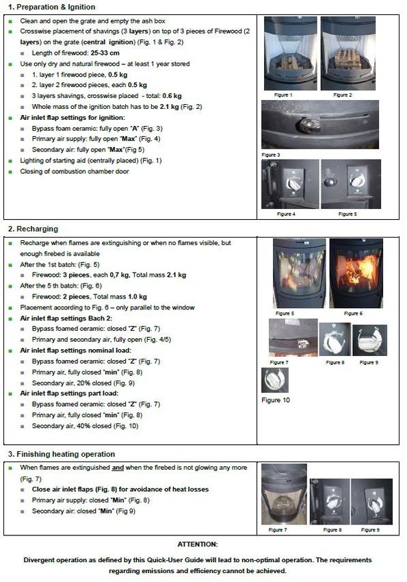
20 ERA-NET Bioenergy Project WoodStoves2020
 Guidelines for Low Emission and High Efficiency Stove Concepts
testing would have to be performed using this longer pipe, which would consequently lead to
higher measured efficiency. However, such behaviour not only creates confusion for the end
user, it also fuels the ongoing debate about deliberate manipulation of type tests. Such
"stove designs" should therefore clearly be avoided.

Figure 8: Field test results for combustion efficiency of log wood stoves as a function of the
length of the connecting pipe to the chimney (Results from 8 log wood stoves tested during
beReal-project [11], no differentiation for flue gas temperature variation can here be made)
However, there are limitations for such measures, as for certain buildings the chimney-
entrance-temperature needs to be kept high enough in order to guarantee sufficient draught
and to prevent condensation of the flue gas.

11 Recommendations regarding user documentation
Apart from the chosen fuel and the technological state of the stove, user behaviour was
identified as the most influencing parameter regarding efficiency and emissions of log wood
stoves [10]. The results of field measurements within the European "beReal-project" [11] had
shown that the availability of a Quick User Guide (QUG) can significantly improve stove
performance in every day operation. The QUG includes all necessary information for stove
operation compiled on only one single page.
It is therefore highly recommended that the manufacturer provides such a Quick User Guide
with the stove. For creating the QUG it is required that the manufacturer has thoroughly
tested and operated the stove under typical conditions in order to conclude on the best
practice which is described in an easily understandable manner for the end user. This shall
also help to avoid usual operating errors and failures.
You can also read