The CMS Experiment at the LHC
←
→
Page content transcription
If your browser does not render page correctly, please read the page content below
Chapter 2
The CMS Experiment at the LHC

The Large Hadron Collider  √ (LHC) [1] is designed to collide proton beams at a
center-of-mass energy of s = 14 TeV and a nominal instantaneous luminosity of
L = 1034 cm−2 s−1 . This represents a seven-fold increase in energy and a hundred-
fold increase in integrated luminosity over the previous hadron collider experiments.
The beam energy and the design luminosity have been chosen in order to study
physics at the TeV energy scale. The main motivation of the LHC is to reveal the
nature of electroweak symmetry breaking and to investigate potential manifestations
of new physics phenomena beyond the SM.
   The unprecedented high center-of-mass energy and luminosity at the LHC lead to
a number of substantial experimental challenges. In this chapter an introduction of
the experimental facility is presented. An overview of the basic aspects of the LHC is
followed by a detailed description of the CMS experiment and its main subdetectors.

2.1 The Large Hadron Collider

The LHC accelerator is located at CERN near Geneva in the already existing LEP
tunnel which has a length of 26.7 km. Four detectors are installed in the experimental
caverns around the collision points: Two general purpose experiments, ATLAS [2]
and CMS [3, 4], the LHCb [5] experiment dedicated to B Physics and the ALICE [6]
experiment where the physics of heavy ion collisions is investigated.
    To supply the LHC with pre-accelerated protons the existing CERN facilities have
been upgraded. A schematic view of the LHC accelerator with the injection chain
is shown in Fig. 2.1. The protons coming from the Super Proton Synchrotron (SPS)
with an energy of 450 GeV are injected into the LHC, where they will be accelerated
to an energy of 7 TeV in bunches with a nominal number of 1.15 · 1011 particles per
bunch. Superconducting dipole magnets which provide a magnetic field of 8.3 T are
needed to keep the protons on the orbit during the acceleration. The superconducting
magnets are cooled using liquid helium at a temperature of 1.9 K.

L. Caminada, Study of the Inclusive Beauty Production at CMS and Construction       7
and Commissioning of the CMS Pixel Barrel Detector, Springer Theses,
DOI: 10.1007/978-3-642-24562-6_2, © Springer-Verlag Berlin Heidelberg 2012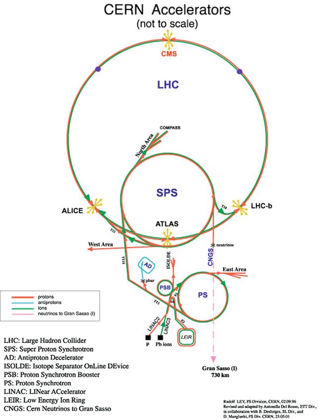
8                                                      2 The CMS Experiment at the LHC

    At the interaction point where the CMS experiment is located collisions hap-
pen every 25 ns, corresponding√to a bunch crossing frequency of 40 MHz. The total
proton-proton cross section at s = 14 TeV is expected to be about 100 mb. There-
fore, approximately 109 inelastic events per second will be observed in the multi-
purpose experiments at design luminosity.
    In the first year of LHC
                           √ running the proton-proton collisions happen at a lower
center-of-mass energy of s = 7 TeV and at a lower luminosity than what is foreseen
in the
    √ original design. A commissioning run with collisions at center-of-mass energies
of s = 900 GeV√and 2.36 TeV took place in November and December 2009. The
LHC operation at s = 7 TeV started on March 30, 2010.

2.2 The CMS Detector

The CMS detector is a general purpose detector installed 100 m underground at the
LHC interaction point 5 (P5) near the village of Cessy in France. The design of
the CMS detector is driven by the challenges of a physics experiment in the LHC
environment. Many of the physics benchmark channels have a small cross section
and the background from QCD jet production is overwhelmingly dominant. A high
rejection power with an optimal efficiency for rare channels has to be achieved. The
reconstruction of lepton signatures is essential for the extraction of rare processes and
an excellent muon and electron identification and momentum resolution is desired.
Moreover, a precise measurement of secondary vertices and impact parameters is
necessary for an efficient identification of heavy flavor and τ -lepton decays.
   The short bunch crossing separation and the high event rate at the LHC impose
further challenges to the design. At design luminosity, 23 inelastic interaction per
bunch crossing will occur on average. This phenomenon is know as pile-up. The
effect of pile-up can be reduced by using high-granularity detectors resulting in
low occupancy. This requires a large number of detector channels and an excellent
synchronization among them. In addition, a good time resolution is needed to dis-
criminate the interaction under study from the interactions occurring in neighboring
bunch crossings. Another difficulty arises from the large flux of particles near the
interaction point which leads to high radiation levels and the need of radiation hard
detectors and front-end electronics.
   The CMS detector is divided into a silicon tracking system, an electromagnetic
and a hadronic calorimeter and a muon system. A magnetic field of 3.8 T is provided
by a superconducting solenoid magnet. The CMS detector is 22 m long, has a diam-
eter of 15 m and an overall weight of 12.5 t. Figure 2.2 presents a schematic view of
the CMS detector.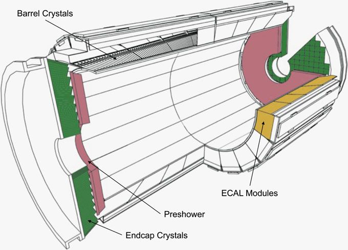
2.2 The CMS Detector                                                                       9

Fig. 2.1 The CERN accelerator complex. Schematic view of the LHC and the location of the four
main experiments ATLAS, CMS, LHCb and ALICE

2.2.1 Coordinate Conventions

The CMS coordinate system is oriented such that the x-axis points south to the center
of the LHC ring, the y-axis points vertically upward and the z-axis is in the direction
10                                                     2 The CMS Experiment at the LHC

                                              Superconducting Solenoid
                                                                Silicon Tracker
Very-forward
Calorimeter                                                        Pixel Detector

                                                                           Preshower

     Hadronic
     Calorimeter
               Electromagnetic
                                                                             Muon
               Calorimeter
                                                                             Detectors
                            C ompac t Muon S olenoid

Fig. 2.2 Schematic view of the CMS detector

of the beam to the west. The azimuthal angle φ is measured from the x-axis in the
x y plane and the radial coordinate in this plane is denoted by r . The polar angle θ is
defined in the r z plane and the pseudorapidity is η = −ln tan(θ/2). The momentum
component transverse to the beam direction, denoted by pT , is computed from the
x- and y-components, while the transverse energy is defined as E T = E sin θ.

2.2.2 Solenoid

A superconducting solenoid magnet with a maximum magnetic field of 3.8 T provides
the large bending power for high-energy charged particles to precisely measure their
momentum in the tracking detectors. The magnetic coil is 13 m long, has an inner
diameter of 6 m and accommodates the tracking and part of the calorimeter detectors.
With these dimensions the CMS solenoid is the largest superconducting magnet ever
built and has the capacity to store an energy of 2.6 GJ at full current. The magnetic
flux is returned through a 10,000 t iron yoke in which the muon detector chambers are
integrated. The CMS solenoid was fully tested and commissioned at the experimental
surface hall during autumn 2006.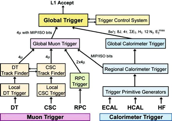
2.2 The CMS Detector                                                                11

2.2.3 Tracking Detectors

CMS features an all silicon tracker with a total active area of 200 m2 . The tracking
detector is divided into a pixel detector close to the interaction region and a strip
detector covering radii between 0.2 and 1.2 m. At LHC design luminosity more than
1,000 particles are expected to traverse the tracking volume in each bunch crossing.
This leads to a hit rate density of 1 MHz/mm2 at a radius of 4 cm which imposes severe
challenges to the design of the tracking detectors. With a pixel size of 100 × 150 μm2
an occupancy of less than 10−4 can be maintained in the pixel detector. As the particle
flux decreases with the distance from the interaction point, sensors with a length of
10 cm and a pitch of 80 μm can be used at intermediate radii (20–55 cm) and sensors
with a length of 25 cm and a pitch of 180 μm at the outermost radii (55–110 cm)
with an occupancy of less than 3%. The sensor thickness is 285 μm for the pixel and
320 or 500 μm for the strip modules at the intermediate and outer radii, respectively.
The thicker sensors for the outer tracking region permit to preserve a signal to noise
ratio well above 10 in spite of the higher noise due to the larger capacity of the
longer strips. To mitigate the radiation damage effects and prolong the lifetime of the
detector modules, the tracking detectors are designed to run at subzero temperatures.
The cooling is established using a mono-phase liquid cooling system whit C6 F14 as
cooling fluid.
    The pixel detector is built from 3 barrel layers at radii of 4.4, 7.3 and 10.2 cm
and two end disks on each side at a distance of z = ±34.5, ±46.5 cm from the
interaction point. It consists of 1,440 segmented silicon sensor modules with a total
of 66 million readout channels. For each pixel the analog pulse height information
is detected and read out.
    The sensor surface of the barrel modules is parallel to the magnetic field, while
the modules in the forward detector are tilted by 20◦ . The charge carriers produced
by a particle traversing the sensor thus experience the Lorentz force and do not drift
along the electric field line anymore. Hence, the charge carriers are distributed over
several pixels. The analog pulse height information can be used to calculate a center
of gravity of the charge distribution which improves the hit information. In this way
a position resolution of about 15 μm in both the r φ and z directions is obtained
(compare to Fig. 2.6). A detailed description of the design and the functioning of the
CMS pixel barrel detector is given in Chap. 7.
    The silicon strip tracker has a length of 5.8 m and a diameter of 2.4 m and is
composed of four subsystems: the four-layer Tracker Inner Barrel (TIB), the six-
layer tracker outer barrel (TOB) and on each side three-disk Tracker Inner Disks
(TID) and nine-disk Tracker Endcaps (TEC). An r z-view of the tracker geometry is
shown in Fig. 2.3.
    The silicon strip tracker is built from 15,148 single-sided modules that provide
9.3 million readout channels. Modules for the TIB, the TID and the first four rings
of the TEC are single-sided while the TOB and the outer three rings of the TEC are
equipped with double-sided modules. A double-sided module is constructed from
two single-sided modules glued back-to-back at a stereo angle of 100 mrad.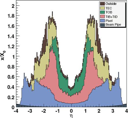
12                                                       2 The CMS Experiment at the LHC

Fig. 2.3 r z-view of the CMS tracking detectors [4]. Single lines represent layers of modules
equipped with one sensor, double lines indicate layers with back-to-back modules

2.2.4 Track Reconstruction

Due to the magnetic field charged particles travel through the tracking detectors on
a helix trajectory which is described by 5 parameters: the curvature κ, the track
azimuthal angle φ and polar angle η, the signed transverse impact parameter d0 and
the longitudinal impact parameter z 0 . The transverse (longitudinal) impact parameter
of a track is defined as the transverse (longitudinal) distance of closest approach of
the track to the primary vertex.
   The main standard algorithm used in CMS for track reconstruction is the Combi-
natorial Track Finder (CFT) algorithm [7] which uses the reconstructed positions of
the passage of charged particles in the silicon detectors to determine the track para-
meters. The CFT algorithm proceeds in three stages: track seeding, track finding and
track fitting. Track candidates are best seeded from hits in the pixel detector because
of the low occupancy, the high efficiency and the unambiguous two-dimensional
position information.
   The track finding stage is based on a standard Kalman filter pattern recognition
approach [8] which starts with the seed parameters. The trajectory is extrapolated to
the next tracker layer and compatible hits are assigned to the track on the basis of the
χ2 between the predicted and measured positions. At each stage the Kalman filter
updates the track parameters with the new hits. In order to take into account possible
inefficiencies one further candidate is created without including any hit information.
The tracks are assigned a quality based on the χ2 and the number of missing hits and
only the best quality tracks are kept for further propagation. Ambiguities between
tracks are resolved during and after track finding. In case two tracks share more than
50% of their hits, the lower quality track is discarded.
   For each trajectory the finding stage results in an estimate of the track parameters.
However, since the full information is only available at the last hit and constraints
2.2 The CMS Detector                                                                                13

Fig. 2.4 Track reconstruction efficiency for muons (left) and pions (right) with transverse momenta
of 1, 10 and 100 GeV [4]

applied during trajectory building can bias the estimate of the track parameters, all
valid tracks are refitted with a standard Kalman filter and a second filter (smoother)
running from the exterior towards the beam line.
    The expected performance of the track reconstruction is shown in Fig. 2.4 for
muons, pions and hadrons. The track reconstruction efficiency for high energy muons
is about 99% and drops at |η| > 2.1 due to the reduced coverage of the forward
pixel detector. For pions and hadrons the efficiency is in general lower because of
interactions with the material in the tracker. The material budget of the CMS tracker
in units of radiation length1 is presented in Fig. 2.5.
    In Fig. 2.6 the transverse momentum resolution for muon tracks with pT = 1, 10
and 100 GeV is shown. At high momenta the resolution is around 1–2% for
|η| < 1.6. The material of the tracker accounts for 20–30% of the transverse momen-
tum resolution. At lower momenta, the resolution is dominated by multiple scattering
and its distribution reflects the amount of material traversed by the track. The reso-
lution of the track impact parameters in the longitudinal and the transverse plane are
also shown in Fig. 2.6. At high momentum the transverse impact parameter resolution
is fairly constant and is dominated by the hit resolution in the first pixel layer. It is
progressively degraded by multiple scattering at lower momenta. The same applies to
the longitudinal impact parameter resolution. The improvement of the z 0 resolution
up to |η| = 0.5 is due to the charge sharing effects among neighboring pixels.

2.2.5 Electromagnetic Calorimeter

The CMS electromagnetic calorimeter (ECAL) is a hermetic and homogeneous
detector with a large pseudorapidity coverage up to |η| < 3. The ECAL is divided

1 The radiation length X 0 is a characteristic of a material, related to the energy loss of high energy
electrons in the material.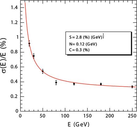
14                                                         2 The CMS Experiment at the LHC

Fig. 2.5 Material budget
of the CMS tracker in units of
radiation length X 0 as a func-
tion of pseudorapidity divided
into the contributions of the
different subdetectors [4]

Fig. 2.6 Resolution of track transverse momentum (left), transverse impact parameter (middle) and
longitudinal impact parameter (right). The resolution is shown for muons with transverse momenta
of 1, 10 and 100 GeV [4]

into barrel and endcap detectors as illustrated in Fig. 2.7. Scintillation crystals made
from lead tungstate (PbWO4 ) are used to measure the energy of electromagnetically
interacting particles, mainly electrons and photons. The choice of PbWO4 as the
material for the scintillation crystal is motivated by its fast response time and high
radiation resistance. The ECAL consists of 61,200 crystals in the barrel and 7,324
crystals in the endcaps. The crystals have a tapered shape and are mounted in a quasi-
projective geometry. With a crystal front face of 22 × 22 mm2 and 28.6 × 28.6 mm2
in the barrel and the endcaps, respectively, a fine granularity is ensured. The length of
a barrel crystal is 23 cm which corresponds to 25.8 X0 , while the endcap crystals are
22 cm long corresponding to 24.7 X0 . The scintillation light produced in the crystals
is read out by avalanche photo diodes (APD) with an active area of 5 × 5 mm2 in
the barrel and by vacuum phototriodes (VPT) with an active area of 280 mm2 in the
endcaps. The light output and the amplification have a strong temperature depen-
dence. The response to an incident electron changes by (3.8 ± 0.4)%/◦ C which in
2.2 The CMS Detector                                                              15

Fig. 2.7 Schematic view of the CMS Electromagnetic Calorimeter [4]

turn means that the temperature has to be closely monitored and kept stable to a
precision of ±0.05 ◦ C. The nominal operating temperature of the ECAL is 18 ◦ C
and is provided by a water cooling system.
   The ECAL barrel has a volume of 8.14 m3 and its front face is at a radial distance
of 1.29 m from the interaction point. It has a 360-fold azimuthal segmentation and
two times 85-fold segmentation in pseudorapidity. The endcap has a coverage of
1.479 < |η| < 3 and is situated at a longitudinal distance of 3.15 m from the
interaction point. A preshower detector with a thickness of 3 X 0 is placed in front
of the endcaps (1.653 < |η| < 2.6) to guarantee a reliable discrimination of single
photons and photons produced in pairs in neutral pion decays.
   The energy resolution of the electromagnetic calorimeter can be parametrized by
the following expression:

                           σ 2                2              2
                                            S                 N
                                   =       √          +                + C2     (2.1)
                            E                E                E

where S is the stochastic term, N the noise term and C the constant term. The value
of the three parameters were determined by a electron test beam measurement to be
                 1
S = 0.028 GeV 2 , N = 0.12 GeV and C = 0.003. The ECAL energy resolution as
a function of the energy of electrons is shown in Fig. 2.8.
16 2 The CMS Experiment at the LHC
Fig. 2.8 ECAL energy
resolution as a function
of the energy measured in
an electron test beam [4].
The measured values of the
stochastic (S), noise (N) and
constant (C) term are dis-
played in the legend
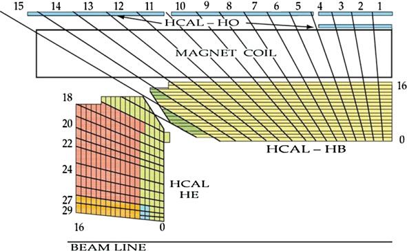
Table 2.1 Tower segmentation in azimuthal and polar angle for the hadronic barrel, endcap and
forward calorimeter
HB/HO HE |η| 2.5 HE |η| > 2.5 HF |η| 4.7 HF |η| > 4.7
φ × η 0.087 × 0.087 0.087 × 0.087 0.175 × 0.175 0.175 × 0.175 0.175 × 0.35
2.2.6 Hadronic Calorimeter
The energy measurement of the ECAL is complemented by the measurement of the
hadronic calorimeter (HCAL). The HCAL is a sampling calorimeter built from alter-
nating layers of massive absorbing brass plates and plastic scintillator tiles arranged in
trays. The quality of the energy measurements depends on the fraction of the hadronic
shower detected in the calorimeter. Consequently, the thickness of the material in the
tray has to be large enough to absorb the major part of the shower. The dimensions
of the barrel part of the HCAL however are restricted to the limited volume between
the outer extent of the ECAL (r = 1.77 m) and the inner extent of the magnetic coil
(r = 2.95 m). Thus, the HB is supplemented by an outer hadronic calorimeter (HO)
located between the solenoid and the muon detectors. The HO uses the solenoid
as additional absorbing material and provides sufficient containment for hadronic
showers with a thickness of 11.8 interaction lengths (λl ). The hadronic calorimeter
is divided into a barrel part (HB and HO) at |η| < 1.3, an endcap (HE) on each side at
1.3 < |η| < 3 and a forward calorimeter (HF) extending up to |η| < 5.2 to achieve a
most hermetic detector coverage. The HCAL tower segmentation in the r z plane for
one quarter of the HB, HO and HE detectors is shown in Fig. 2.9 and summarized
in Table 2.1.2.2 The CMS Detector 17
Fig. 2.9 Tower segmentation for one quarter of the HCAL displayed in the r z plane [4]. The colors
represent the optical grouping of scintillator layers into different longitudinal readouts
The plastic scintillator tiles are read out by wavelength shifting fibers that shift the
blue-violet light emitted by the scintillator to green light which is then sent through
transparent fibers to hybrid photodetectors (HPDs) with 19 independent pixels. The
first scintillators are placed in front of the first absorber plate in order to sample
showers developing in the material between the ECAL and the HCAL, while the last
scintillators are installed after the last absorber plate to correct for late developing
showers leaking out. 70,000 and 20,916 scintillator tiles are installed in the HB and
the HE, respectively.
The HF is positioned at a longitudinal distance of 11.2 m from the interaction
point. It will experience unprecedented particle fluxes with√ an energy of 760 GeV
deposited on average in a proton-proton interaction at s = 14 TeV. This energy
has to be compared to the average of 100 GeV deposited in the rest of the detector.
The situation is even more severe as the energy is not spread equally among the
HF, but has a pronounced peak at the highest rapidity. The HF is made from steel
absorber plates composed of 5 mm thick grooved plates with quartz fibers inserted
as active medium. It detects the Cherenkov light emitted by charged particles in the
shower and is thus mainly sensitive to the electromagnetic component of the shower.
A longitudinal segmentation in two parts allows to distinguish signals generated by
electrons and photons from signals generated by hadrons.
2.2.7 Muon System
The muon system is the outermost part of the CMS detector. The magnet return yoke
is equipped with gaseous detector chambers for muon identification and momentum
measurement. In the barrel, the muon stations are arranged in five separate iron wheels18 2 The CMS Experiment at the LHC
Fig. 2.10 View of one quarter of the CMS detector illustrating the layout of the muon system in
the barrel and the endcap region [4]
and in the endcap, four muon stations are mounted onto the three independent iron
disks in the positive and the negative endcaps. Each barrel wheel is segmented into
12 sectors in azimuthal angle.
Three different types of gaseous detectors are integrated into the CMS muon
system depending on the requirements. In the barrel part where both the muon rate and
the neutron induced background are small and the magnetic field is very low, drift tube
(DT) chambers are used. In the endcaps however the muon and the background flux is
much higher. The muon detector endcaps are thus built from cathode strip chambers
(CSCs) which provide a faster response, a higher granularity and a better resistance
against radiation. In addition, resistive plate chambers (RPCs) form a redundant
trigger system. In total, the CMS muon system consists of 250 DT chambers, 540
CSCs and 610 RPCs. The arrangement of the detector chambers is shown in Fig. 2.10.
A DT cell is a 4 cm wide gas tube with a positively charged stretched wire inside.
Each DT chamber, on average 2 × 2.5 m in size, consists of 12 layers of DT cells,
arranged in three groups of four. The middle group measures the z coordinate while
the two outside groups measure the r φ coordinate. In the barrel, four DT chambers
are interspersed with the layers of the flux return yoke in each φ sector. The outermost
muon station is equipped with DT chambers that contain only 8 layers of DT cells
and determine the muon position in the r φ plane. The barrel part of the muon system
covers the region |η| < 1.2.2.2 The CMS Detector 19
The CSCs are trapezoidal shaped multiwire proportional chambers which consist
of 6 anode wire planes crossed with 7 copper strips cathode panels in a gas volume.
They provide a two-dimensional position measurement, where the r and φ coor-
dinates are determined by the copper strips and the anode wires, respectively. The
muon detector endcaps consist of 4 CSC stations on each side and identify muons in
the pseudorapidity range of 0.9 < |η| < 2.4.
RPCs are made from two high resistive plastic plates with a voltage applied and
separated by a gas volume. The signal generated by the muon when passing through
the gas volume is detected by readout strips mounted on top of one of the plastic
plates. The RPCs used in the muon trigger system are highly segmented and have a
fast response with a time resolution of 1 ns. Six layers of RPCs are installed in the
barrel muon system, two layers in each of the first two stations and one layer in each
of the last two stations. One layer of RPCs is built into each of the first three stations
of the endcap.
2.2.8 Muon Reconstruction
Muon reconstruction, after local-pattern recognition is performed in two stages:
stand-alone reconstruction based on information from the muon system only and
global reconstruction including the hit information of the silicon tracker. Stand-
alone reconstruction starts from track segments in the muon chambers and muon
trajectories are built from the inside to the outside using the Kalman filter technique.
After the trajectory is built, a second Kalman filter, working from outside in, is
applied to determine the track parameters. In the end, the track is extrapolated to
the nominal interaction point and a vertex-constrained fit of the track parameters is
performed.
In the global muon reconstruction the muon trajectories are extended to add hits
measured by the tracker. The track parameters of a stand-alone reconstructed muon
are compared to the track parameters of the tracker tracks by extrapolating the tra-
jectories to a common plane on the inner surface of the muon detector. If a tracker
track is found that is compatible in momentum, position and direction, the hit infor-
mation of the tracker and the muon system is combined and refitted to form a global
muon track. The resulting global tracks are then checked for ambiguity and quality
to choose at most one global track per stand-alone muon.
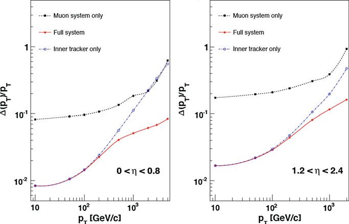
The precision of the momentum measurement in the muon system is essentially
determined by the measurement of the bending angle in the transverse plane at the
exit of the magnetic coil. This measurement is dominated by multiple scattering in the
material before the first muon station up to transverse momentum values of 200 GeV.
For low-momentum muons the momentum resolution is improved substantially by
including the measurement of the silicon tracker. The analysis presented here inves-
tigates muons with a transverse momentum between 6 and 30 GeV. The inclusion of
the tracker information by using global muons is thus most valuable. In Fig. 2.11 a
comparison of the momentum resolution of the muon system, the tracker system and
a combined measurement is given for the barrel and the forward region.20 2 The CMS Experiment at the LHC
Fig. 2.11 Muon transverse momentum resolution as a function of the transverse momentum for
muons detected in the barrel (left) and the endcap (right) regions [4]. The resolution is given for
the measurement using the muon system or the tracking system only and for a combined method
2.2.9 Trigger System
The CMS trigger system is designed to cope with the unprecedented high luminosity
and interaction rates. It must ensure high data recording efficiency for a wide variety
of physics objects and event topologies, while applying online selective requirements
to reduce the 40 MHz event rate to an output rate of about 100 Hz allowing for
permanent storage of an event.
The CMS trigger system reduces the event rate in two steps called Level 1 (L1) and
High Level Trigger (HLT). The L1 trigger is designed to achieve a maximum output
rate of 100 kHz and consists of custom-designed, programmable electronics while
the HLT is based on software algorithms running on a large cluster of commercial
processors, the event filter farm.
The L1 trigger system uses only coarsely segmented data from the muon system
and the calorimeters while the full granularity data are stored in the detector front-
end electronics waiting for the L1 decision. The L1 decision has to be taken within
a latency time of 3.2 μs and is based on the decision of local, regional and global
trigger components. It also depends on the readiness of the other subdetectors and the
data acquisition system (DAQ) which is supervised by the Trigger Control System.
The trigger architecture is displayed in Fig. 2.12.
The ECAL and the HCAL cells form trigger towers with an (η, φ) coverage of
0.087 × 0.087 in |η| < 1.74 and larger size in the forward region. Trigger primitives2.2 The CMS Detector 21
Fig. 2.12 L1 trigger architecture [4]
are generated by calculating the transverse energy of a trigger tower and assign-
ing it to the correct bunch crossing. A regional calorimeter trigger then determines
regional electron, photon and jet candidates and information relevant for muon and
tau identification. The global calorimeter trigger provides information about the jets,
the total transverse energy and the missing energy in the event and identifies the
highest-ranking trigger candidates.
In the muon system all three types of detectors take part in the trigger decision. The
DT chambers provide track segments in the φ projection and hit pattern in η, while
the CSC determine three-dimensional track segments. The track finders in the DT
chambers and the CSCs calculate the transverse momentum of a track segment and
its location and quality. The RPCs deliver an independent measurement derived from
regional hit patterns. The global muon trigger receives up to four candidates from
each subsystem (DT, barrel RPC, CSC and endcap RPC) together with the isolation
information from the global calorimeter trigger. The aim is to improve the efficiency
and to reduce the rate by making use of the complementarity and the redundancy of
the subsystems. In the end, the global muon trigger selects a maximum of four muon
trigger candidates and determines their momentum, charge, position and quality.
The trigger objects extracted by the global calorimeter trigger and the global muon
trigger are sent to the global trigger where the decision to accept or reject an event
is taken and distributed to the subdetectors. The decision is based on the results
of algorithms which for example apply momentum thresholds to single objects or
require object multiplicities to exceed predefined values. Up to 128 algorithms can
be executed in parallel.22 2 The CMS Experiment at the LHC
If an event is accepted by the L1 trigger, the full detector information (∼1 MB) is
read out by the DAQ system at a rate of up to 100 kHz, passed to the event filter farm
and used as input for the HLT. The HLT algorithms are implemented in the same
software as used for offline reconstruction and analysis and consist of subsequent
reconstruction and selection steps. The framework uses a modular architecture and
the modules to be executed are defined at runtime by means of configuration files.
The HLT menu is composed of a set of trigger paths, each path addressing a specific
physics object selection. The execution of a path is interrupted if the processed event
does not fulfill the conditions imposed by a given filter module. The trigger menu
for the first CMS data taking can be found in [9].
References
1. O.E. Bruning et al., LHC Design Report, vol. I: The LHC Main Ring, CERN-2004-003-V-1
(2004)
2. ATLAS Collaboration, Detector and Physics Performance Technical Design Report, vol. 1,
CERN-LHCC-99-14 (1999)
3. CMS Collaboration, The Compact Muon Solenoid: Technical Proposal, CERN-LHCC-94-38
(1994)
4. CMS Collaboration, The CMS experiment at the CERN LHC, JINST 3, S08004 (2008)
5. LHCb Collaboration, LHCb Technical Proposal, CERN-LHCC-98-04 (1998)
6. ALICE Collaboration, Technical Proposal for a Large Ion Collider Experiment at the CERN
LHC, CERN-LHCC-95-71 (1995)
7. W. Adam et al., Track Reconstruction in the CMS Tracker, CMS NOTE-2006/041 (2006)
8. P. Billoir, Comput. Phys. Commun. 57, 390 (1989)
9. CMS Collaboration, CMS High Level Trigger, CERN/LHCC 2007-021 (2007)You can also read