THE COMPLETE REFERENCE GUIDE - RHINOCAM-ART 2022 - MECSOFT CORPORATION
←
→
Page content transcription
If your browser does not render page correctly, please read the page content below

The Complete
Reference Guide
  RhinoCAM-ART 2022
            Thursday, April 7, 2022

                                      MecSoft Corporation
                                        © Copyright 1998-2022
RhinoCAM-ART 2022
                      by MecSoft Corporation

User Notes:
________________________________
________________________________
________________________________
________________________________
________________________________
________________________________
________________________________
________________________________
________________________________
________________________________
________________________________
________________________________
________________________________
________________________________
________________________________
________________________________
________________________________
________________________________
________________________________
________________________________
Contents 2
Table of Contents
Quick Start 4
Resource Guide 7
Welcome 8
1 Overview
...................................................................................................................................
of ART 9
2 Features
...................................................................................................................................
of ART 9
3 Understanding
...................................................................................................................................
ART 10
4 Typical
...................................................................................................................................
Scenario 11
5 Work-flow
................................................................................................................................... 12
User Interface 14
1 ART Menu
...................................................................................................................................
Bar Item 14
2 ART Browser
................................................................................................................................... 15
Relief Operations
..........................................................................................................................................................
tab 17
Raster to Vector
..........................................................................................................................................................
tab 18
Docking the ART
..........................................................................................................................................................
Brow ser 19
3 ART Online
...................................................................................................................................
Help 20
Overview of Operation Types 21
1 Create
...................................................................................................................................
3D Relief 21
2 Create
...................................................................................................................................
Puffed Volume 22
3 Sweep
...................................................................................................................................
Volume Generation 23
4 Create
...................................................................................................................................
Curves from Image 24
Creating Relief Operations 26
1 Project
...................................................................................................................................
Setup 26
2 Align...................................................................................................................................
Native Geometry Inside Project Setup 29
3 Move...................................................................................................................................
to Origin 32
4 Convert
...................................................................................................................................
Native Geometry 32
5 Create
...................................................................................................................................
3D Relief from Image 34
6 Create
...................................................................................................................................
Puffed Volume 41
7 Create
...................................................................................................................................
Sweep Volume 51
Relief Curves.......................................................................................................................................................... 56
8 Operation
...................................................................................................................................
Types 57
9 Load ...................................................................................................................................
Shape Library 61
Shape Editor .......................................................................................................................................................... 62
10 Import
...................................................................................................................................
ART 1.0 File 64
© 2022 MecSoft Corporation
2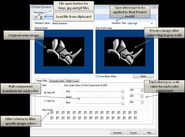
3      RhinoCAM-ART 2022

       11 Export
              ...................................................................................................................................
                 Meshes to CAD                                                                                                                    64
       12 ART Options
              ................................................................................................................................... 64

Creating Raster to Vector Operations                                                                                                                                                69
        1 Create
               ...................................................................................................................................
                  Curves from Image                                                                                                                69

Editing Relief Operations                                                                                                                                                           74
        1 Editing
                ...................................................................................................................................
                    Operations Associatively                                                                                                        74
        2 Regenerating
              ...................................................................................................................................
                            Relief Operation                                                                                                      76
        3 Archiving
               ...................................................................................................................................
                       Relief Operations                                                                                                           77
                   Operation Suppression
                               .......................................................................................................................................................... 79

Find More Resources                                                                                                                                                                 81

            Index                                                                                                                                                                   82

                                                                                                                                                 © 2022 MecSoft Corporation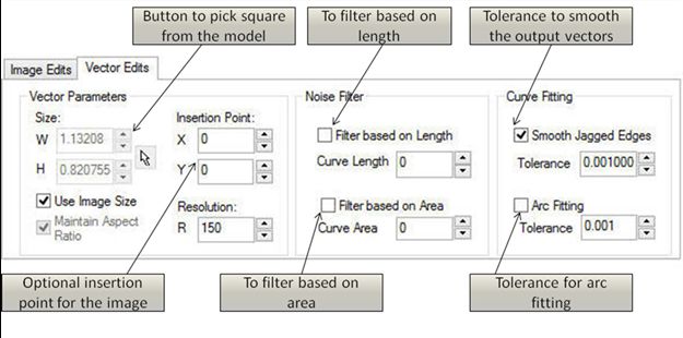
Quick Start        4

Quick Start
          Quick Start Guides for each RhinoCAM module are available in both PDF and Video format. Refer
          to the following information to access these guides:

                     What's New!
                     What's New in RhinoCAM 2022
                     Watch the What's New in 2022 Webinar!

                     The Complete Quick Start Video Play List
                     Here is a link to the complete 2022 Video Play List

                     How to Access the Quick Start Guide Documents
                     To help you quickly get started in working with each module, select one of the Help
                     buttons located on the RhinoCAM Learning Resources dialog.
                     You will find:
                     · Quick Start Guides
                     · What's New documents
                     · Online Help links
                     The Quick Start Guides will help you step through an example tutorial which will
                     illustrate how to use the module. To access the Learning Resources dialog:
                     1. From the Rhino Main Menu, drop down the Main menu and select Learn ...

© 2022 MecSoft Corporation
5   RhinoCAM-ART 2022

                                     To access the Learning Resources dilog in RhinoCAM

        2. Select a document from the Learning Resources dialog to get started using the
           module of your choice.

               You can also select the Open Quick Start Files Folder button located at the bottom
           of the dialog to open the Quick Start folder where the source files (start and
           completed versions) are located.

                                                                                      © 2022 MecSoft Corporation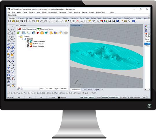
Quick Start   6

                                           Learning Resources Dialog

                     Related Topics
                     Find More Resources

© 2022 MecSoft Corporation
7      RhinoCAM-ART 2022

Resource Guide
      Download this PDF Guide for a list of the available RhinoCAM Resources.

              2022 RhinoCAM Resource Guide

                                       The 2022 RhinoCAM Resource Guide!
                                       18 Pages
                                       Lists PDF downloads and Online resources including Quick Start
                                       Guides, Reference Guides, Exercise Guides, Tutorials and
                                       More.

                                       Prefer Printed Documentation? Check Here!

                                                                                © 2022 MecSoft Corporation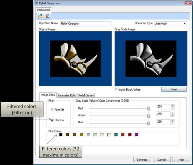
Welcome   8

Welcome

                                        RHINOCAM2022

                              Prefer Printed Documentation? Check Here!
          Welcome to the on-line help system for the RhinoCAM module included with your MecSoft CAM
          software. This online help system provides comprehensive help topics as well as context
          sensitive help to dialogs that will help you become productive with the RhinoCAM module.
          For purposes of brevity, RhinoCAM will be referred to as ART in all subsequent references. Also,
          Rhino refers to both Rhinoceros 6 or Rhino 7.

                                         On-line help compiled on: Thursday, April 7, 2022

                     Related Topics
                     Overview of ART
                     Features of ART
                     Understanding ART
                     Typical Scenario

© 2022 MecSoft Corporation
9      RhinoCAM-ART 2022

                   Work flow

3.1       Overview of ART
          ART is a module that runs inside of the RhinoCAM product. This module is fully integrated inside
          of Rhinoceros 6 (or Rhino 7) and compliments the CAD functionality of Rhinoceroswith additional
          artistic modeling capabilities. ART’s capabilities enable you to produce 3D models as well as
          wireframe geometry from picture files. The created geometry can then be exported to
          Rhinoceros for use in other downstream applications such as RhinoCAM.

                   Related Topics
                   The RhinoCAM Module

3.2       Features of ART
          The ART module is used to convert artwork into geometry suitable for machining or any other
          downstream applications such as 3D printing. It augments the traditional modeling capabilities of
          Rhinoceros and allows you to utilize bitmap files to construct geometry. The list below
          summarizes the features found in ART.

                   Relief Operations
                   Relief operations are used to create 3D shapes. The different functions that a user can
                   utilize are:
                      · Convert Native Geometry
                         Convert CAD data to ART geometry
                      · Create 3D Relief
                         Convert bitmap files to 3D geometry based on gray-scale
                      · Create Puffed Volume
                         Create puffed shapes using wireframe geometry as boundaries
                      · Create Swept Volume
                         Performing sweeping operations of cross sectional shape functions along a curve
                         to create 3D geometry

                   Raster to Vector
                   This operation can be used to convert picture or bitmap files (Raster) into wireframe
                   (Vector), by tracing the boundary edges between differently colored regions in the
                   picture file.

                   Shape Library

                                                                                      © 2022 MecSoft Corporation
Welcome 10
You can save created ART geometry to shapes that can be reused in other projects.
Export to CAD
Once 3D or wireframe geometry is created in ART, they can be exported to Rhinoceros
for use in downstream applications. There are various settings that can be used to
control the way the geometry is created in Rhinoceros.
File Formats Supported
Bitmap Files (.bmp), JPEG, JPG Files (.jpg, .jpeg) and GIF Files (.gif)
Related Topics
The RhinoCAM Module
3.3 Understanding ART
The ART module is used to convert artwork into geometry suitable for machining or 3D printing. To
accomplish this, you utilize modeling techniques unique to the ART module that are found within
the “Relief Operations” tabbed browser window or the “Raster to Vector” tabbed browser
window. These modeling operations augment the traditional modeling methods available in
Rhinoceros.
The created geometry will be displayed on the graphics screen by the ART module for easy
visualization and modification if necessary. At any point during the geometry creation, the ART
geometry can be exported to Rhinoceros. This geometry can then be used in any downstream
applications to create the physical part. The standard work flow of ART module mimics this
process and can be represented by the flow chart shown below.
© 2022 MecSoft Corporation11 RhinoCAM-ART 2022
Understanding ART
Related Topics
The RhinoCAM Module
3.4 Typical Scenario
Modeling in ART starts with defining a project workspace. The project workspace specifies the
extents of the finally created model. Various operations such as Creating 3D Relief from a bitmap
image (.bmp, .jpg, and .gif), Image to Curve geometry conversion, Sweep Volume Generation,
Puffed Volume Generation can be specified within this workspace. These operations, once
created, will be displayed in the ART browser in a tree structure. The project workspace model
represents the state of the model after each and every operation’s geometry has been combined
into one final shape. The combination is defined using rules (called Operation Type in each of the
operation dialogs) that can be selected when creating the operation.
Selecting any of the operation icons in the tree display in the
ART Browser will display the corresponding shape on the
© 2022 MecSoft CorporationWelcome 12
graphics screen. Selecting the project icon in the browser will
display the shape of the entire project, obtained by combining all
of the individual operations that make up the project.
By using a combination of the ART tools, and a variety of bitmaps and operations, different shapes
can be created. If any operation is not to your expectation, it can be edited to modify any of the
parameters used to create the shape. Operations can also be deleted easily by simply deleting the
operation icon in the tree display. After a satisfactory model is generated, the entire project can
be exported to Rhinoceros as 3D mesh geometry. This mesh is now ready to be used for machining
using software such as RhinoCAM's milling module.
Related Topics
The RhinoCAM Module
3.5 Work-flow
Once the part is loaded, the typical work flow is reflected in the layout of the tabs of the ART
Browser window. The work flow is designed to allow you to work from either the Relief
Operation tab or Raster to Vector tab. As each tab is accessed, a toolbar with functions specific to
the tab chosen will be displayed just below the tab. The functions in each of the toolbars
corresponding to each tab are also best accessed in order from left to right.
Thus you typically would start with either the Relief Operations tab or the Raster to Vector tab and
access each of the buttons, optionally, in the toolbar that appears when either of these tabs is
selected in sequence from left to right. Once the setup functions are completed, you will then
proceed to the Relief Operations to commence programming the part. Once relief operations or
raster to vector operations are completed you can export the meshes or curves to CAD.
Step 1: Relief Operations tab or Raster to Vector tab
· Create project, create curves, load shape library, import ART 1.0 file or modify
preferences
· Create Relief Operations, align native geometry, move selections to origin or
convert native geometry
Step 2: Export Models to CAD
· Export relief operations meshes to CAD
· Export vector operations curves to CAD
Related Topics
© 2022 MecSoft Corporation13 RhinoCAM-ART 2022
The RhinoCAM Module
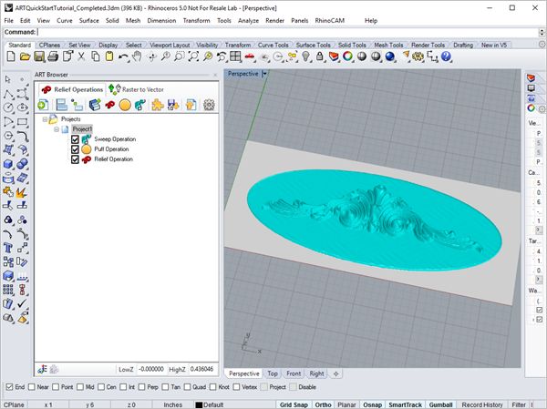
© 2022 MecSoft CorporationUser Interface 14
User Interface
The ART interface adheres to the Windows standard for user interface design and integrated into
the Rhinoceros screen seamlessly. A screen shot of ART running inside of Rhinoceros is shown
below:
ART User Interface
Related Topics
ART Menu Bar Item
ART Browser
ART Online Help
4.1 ART Menu Bar Item
When RhinoCAM is loaded it will add a menu bar item, titled RhinoCAM 2022 to the main Rhino
menu bar. Selecting this menu bar item will display a drop down menu as shown below. Select
ART to display the ART Browser.
© 2022 MecSoft Corporation15 RhinoCAM-ART 2022
Related Topics
ART User Interface
ART Online Help
4.2 ART Browser
When the ART module is loaded from the RhinoCAM menu, the ART browser window will be
displayed. If you are using the default factory settings, this browser window will be docked to the
left hand side of the Rhinoceros product as shown above.
This browser consists of a tabbed toolbar located on top which has two tabs. These tabs are:
1. Relief Operations (ROps) tab
2. Raster to Vector tab
The Relief Operations tab is used for 3D geometry using various operations such as creating
reliefs, sweep and puff operations. In the Raster to Vector tab, raster images can be converted in
to a vector (Curves).
Relief Operations (ROps)
ART allows you to create multiple relief operations in a part file. This feature is the one
that allows you to create the entire sequence of relief operations that are necessary to
create the part model. This set of operations can additionally be archived to a disk file
and retrieved at a later time with no loss of information. The Browser shown below
allows you to manage this list of relief operations.
© 2022 MecSoft CorporationUser Interface 16
Raster to Vector
Selecting the Raster to Vector tab in the ART Browser shows 2 functions that provide the
functionality to create curves from images and export the curves to CAD.
Related Topics
ART User Interface
Relief Operations tab
Raster to Vector tab
Docking the ART Browser
ART Online Help
© 2022 MecSoft Corporation17 RhinoCAM-ART 2022
4.2.1 Relief Operations tab
Project Setup
This option brings up the dialog that allows you to setup a project workspace in the
XY plane.
Align Native Geometry
This option allows you to align native CAD geometry to the project.
Move to Origin
This option allows you to move the objects or geometry to a specified origin within
the project.
Convert Native Geometry
This option allows you to convert native CAD geometry to a relief in the project.
Create 3D Relief from Image
This option brings up the file open dialog which allows you to select the image files
such as gif, bmp and jpg. After a file has been selected, the 3D Relief creation
dialog pops up and you can now change the parameters in the dialog to create relief.
Create Puffed Volume
This option brings up the puffed volume creation dialog. This dialog allows you to
select two sets of curves (border curves and detail curves) and generates a puffed
volume inside the enclosed curve.
Create Sweep Volume
This option allows you to sweep a cross-section curve along the selected rail curve
to generate a swept volume. You can create curves of various cross sections such as
straight lines, arcs (concave or convex) and ellipses (concave or convex).
© 2022 MecSoft CorporationUser Interface 18
Load Shape Library
This brings up the open dialog which allows you to select shapes (.slb files) that
have been previously saved to Shape Library.
Import ART 1.0 File
Selecting this button imports operations from the RhinoART 1.0 plug in to the ART
Browser for part file that is currently loaded.
Export Meshes to CAM
This button allows you to export the ART geometry (meshes) to Rhinoceros. Thus, a
mesh can be easily saved in Rhinoceros and further used in any downstream
applications native to Rhinoceros.
Preferences
This button allows you to set preferences such as File Load Options, Display
Options, Mesh Export Options, and Closed Mesh Options.
Material Texture Visibility
Toggle material texture visibility on and off. When on, the material texture will
display on the part.
Load Shape Library Visibility
Toggle the display of the Shape Library. When toggled on, the Shape Library will
display below the ART Browser.
Related Topics
ART Browser
4.2.2 Raster to Vector tab
Raster to Vector tab
Create Curves from Raster Image
© 2022 MecSoft Corporation19 RhinoCAM-ART 2022
This brings up the file open dialog which allows you to select an image to convert
to RhinoCAM Curves.
Export as Curves to CAD
This button allows you to export the ART geometry (curves) to the MILL module.
Thus, a mesh can be easily saved using the MILL module, and further machined
using any CAM software such as RhinoCAM.
Related Topics
ART Browser
4.2.3 Docking the ART Browser
The ART Browser is a dockable window. This means this window can be docked in any position in
Rhinoceros. This section describes the procedure to be used to dock this window.
Select RhinoCAM 2022 from the menu bar and click ART. This displays the ART Browser and by
default is docked to the left half of the application window next to the view bar.
Selecting the title bar and holding the left mouse button down and dragging the browser window
will display a widget that allows you to dock the browser to desired location.
Related Topics
ART Browser
© 2022 MecSoft CorporationUser Interface 20
4.3 ART Online Help
Select the Help button from any ART dialog to display the Online Help system.
RhinoCAM-ART Online Help
Related Topics
ART User Interface
Relief Operations tab
Raster to Vector tab
Docking the ART Browser
© 2022 MecSoft Corporation21 RhinoCAM-ART 2022
Overview of Operation Types
There are two major classes of operations that can be created in ART module. ART operations are
used to convert artwork into geometry for machining. ART operations can be categorized as Relief
Operations and Raster to Vector operations.
Relief Operations
Create 3D Relief, Create Puffed Volume, Create Swept Volume
Raster to Vector
Create Curves from image
These categories, and the available operations, within them are described in the
sections to follow.
ART allows you to choose from a variety of 3D relief, puffed volume, sweep volume and
vector operations to satisfy various artwork converting conditions and requirements. A
list of the available types with a short description for each type is given below. Selecting
either the 3D Relief Operations tab or Raster to Vector tab in the ART Browser can be
used to access the ART operations. The relief operations under the 3D Relief Operations
tab that can be used are Create 3D Relief, Create Puffed Volume, and Create Swept
Volume. Create curves from image can be selected under the Raster to Vector tab.
Related Topics
Create 3D Relief
Create Puffed Volume
Sweep Volume Generation
Create Curves from Image
5.1 Create 3D Relief
This part is required for converting the Raster images to gray scale image, which in turn will
be converted into the 3D model based on the gray scale values of each pixel in the raster
image.
On selecting the Image file, the Create Relief Operation dialog appears as shown below. As seen
in the dialog below, you can see the original image and the preview image at the same time.
Dialog Box: 3D Relief Operation
© 2022 MecSoft CorporationOverview of Operation Types 22
Dialog Box: 3D Relief Operation
Related Topics
Overview of ART Operation Types
5.2 Create Puffed Volume
This operation is used to puff up the interior of a closed curve. This dialog can be invoked
by pressing the icon from the toolbar of the ART Browser. The dialog is shown in the picture
below:
Dialog Box: Puffing Operation
© 2022 MecSoft Corporation23 RhinoCAM-ART 2022
Dialog Box: Puffing Operation
Related Topics
Overview of ART Operation Types
5.3 Sweep Volume Generation
This method is used for generating a volume along a curve by specifying a type of cross-
section. This dialog can be invoked by pressing icon in the Art Browser toolbar under Relief
Operations tab.
Dialog Box: Sweeping Operation
© 2022 MecSoft CorporationOverview of Operation Types 24
Dialog Box: Sweeping Operation
Related Topics
Overview of ART Operation Types
5.4 Create Curves from Image
This method is mainly used to convert and image outline into curves, so that they can be
used in the next operation. The first step is to convert the image into black and white image
based on the threshold value you defined.
This property page will allow you to load, convert the image to black/white image and preview a
color image to a gray scale bitmap. Also, it allows you to view the converted image into a vector
and to make changes in the image options to review the vector geometry. The dialog for this
implementation will be very similar to the dialog for Raster to 3D Relief. The operation can be
undone if you want to reject the obtained geometry.
© 2022 MecSoft Corporation25 RhinoCAM-ART 2022
Dialog Box: Vector Operation
Dialog Box: Vector Operation
Related Topics
Overview of ART Operation Types
© 2022 MecSoft CorporationCreating Relief Operations 26
Creating Relief Operations
Related Topics
Project Setup
Align Native Geometry Inside Project Setup
Move to Origin
Convert Native Geometry
Create 3D Relief from Image
Create Puffed Volume
Create Sweep Volume
Operation Types
Load Shape Library
Import ART 1.0 File
Export Meshes to CAD
Preferences
6.1 Project Setup
This is the first step required before any relief operation is created. The project setup
dialog defines the workspace extents that you will be using. Any further operations which
appear outside the workspace setup will be ignored.
Dialog Box: Project Setup
© 2022 MecSoft Corporation27 RhinoCAM-ART 2022
Dialog Box: Project Setup
Project Location & Extents / Origin
You can select the Pick Origin button and the dialog box momentarily disappears to allow
you to graphically pick the origin point of the project. Or the numerical value can be
entered as well as using the up/down arrows.
Extents
You can select the Pick Origin & Extents button and the dialog box momentarily
disappears to allow you to graphically pick the origin and the extents (workspace area) of
the project.
Resolution Settings
The resolution defines the accuracy used to generate the actual model. The higher the
resolution, the better the quality of the output mesh generated. However, increasing the
resolution also reduces the relief generation time and above all affects the display.
© 2022 MecSoft CorporationCreating Relief Operations 28
You can use the radio buttons to select Standard, Medium, or Fine. You can also enter the
numerical value desired or use the up/down arrows to specify resolution. Standard range
is 0-99, Medium range is 100-149, Fine range is 150 and above. Depending on the values
entered, the radio button will toggle automatically to the appropriate resolution
designation.
Pick Material
You can select the Pick Material button to specify the material texture desired for the
project. With the Material Texture Visibility enabled, the material texture will be
displayed on the project and operations. When the Pick Material button is selected, the
below dialog box will appear.
Dialog Box: Browse for materials ...
Dialog Box: Browse for materials ...
Color Options
Display Projects in Single Relief or Relief & Base Colors
© 2022 MecSoft Corporation29 RhinoCAM-ART 2022
Here you can select from two color options for your project. Single Relief Color displays
the entire project in one Color. You can then select the Relief Color using the color
selector. Relief & Base Color displays the project in two colors. Use the Relief Color
selector and then also use the Base Color selector. You can also define the Base Z Height
of your Project.
Related Topics
Creating Relief Operations
6.2 Align Native Geometry Inside Project Setup
This command allows you to align native CAD geometry to the project. You can align the
CAD in the X, Y or Z coordinate of the project workspace. You also has the option to offset
the CAD from the edge of the project workspace.
Dialog Box: Align Native Geometry Inside Project Setup
© 2022 MecSoft CorporationCreating Relief Operations 30
Dialog Box: Align Native Geometry Inside Project Setup
X Y Alignments
You can determine where to place the geometry in the X Y coordinates within the
project workspace by selecting the desired X Y alignment coordinate radio button. In
the example below, the X Y alignment that is selected is Center and notice the relief
shapes are centered about the rectangular project.
© 2022 MecSoft Corporation31 RhinoCAM-ART 2022
Offsets from Edge
You can enter a numerical value or use the up/down arrows to specify an offset amount
for either the X or Y or both. The example below shows an offset of X .250 and Y .250
from Center of project.
Align in Z (if using project with thickness)
You has the option to align the geometry within the project workspace in Z if using
project with thickness. You can select the radio button for Align to top, Align to center,
or Align to bottom. Align to top will move the geometry such that the top of the
geometry and the top of the project workspace are flush with each other. Alight to
bottom will do the same to align the bottoms of the two geometries. Align to center
will position the geometry such that its middle Z value and the middle Z value of the
project workspace are the same.
Related Topics
Creating Relief Operations
© 2022 MecSoft CorporationCreating Relief Operations 32
6.3 Move to Origin
This command allows you to move the objects or geometry to a specified origin within the
project. You can select a new origin to move to and select the object(s) to be moved to the
new origin.
Dialog Box: Move to Origin
Dialog Box: Move to Origin
Pick Origin
You can select the Pick Origin arrow and the dialog box momentarily disappears to
allow you to graphically pick the move to origin point of the project. Or the numerical
value can be entered as well as using the up/down arrows.
Pick Objects
By selecting the Select Objects arrow, the dialog momentarily disappears and allows
you to designate the curves to be moved to origin.
Related Topics
Creating Relief Operations
6.4 Convert Native Geometry
This command allows you to convert native CAD geometry to a relief in the project. You can
select a surface or mesh for conversion within the project workspace. This option converts
the CAD geometry suitable for 3D reliefs.
Dialog Box: Move to Origin
© 2022 MecSoft Corporation33 RhinoCAM-ART 2022
Select Surfaces
You can select a solid, surface or mesh for conversion by selecting the Select Surfaces
button. Upon selecting the Select Surfaces button, the dialog will momentarily
disappear and allow you to select a surface or mesh for conversion. Selected items
which appear in the Selected Surfaces list can be easily removed by either using the
Remove Active button to delete single items or use the Remove All button which
removes all items from the list. Below is an example of native geometry converted.
The box that consists of CAD surfaces is shown in gray.
© 2022 MecSoft CorporationCreating Relief Operations 34
The converted native geometry is now part of the project geometry
Related Topics
Creating Relief Operations
6.5 Create 3D Relief from Image
This part is required for converting the Raster images to gray scale image, which in turn will
be converted into the 3D model based on the gray scale values of each pixel in the raster
image.
On selecting the Image file, the Create Relief dialog appears as shown below. As seen in the
dialog below, you can see the original image and the preview image at the same time.
Dialog Box: 3D Relief Operation
© 2022 MecSoft Corporation35 RhinoCAM-ART 2022
Dialog Box: 3D Relief Operation
Operation Name
Allows you to change the name if so desired by typing the new name.
Operation Type
Refer to Operation Type
Invert Black/White
The invert color option is provided for you to be able to invert the gray scale.
The gray scale inversion is required in case the model needs to be created as a
relief depth instead of relief height.
Reset Button
The reset button is provided for you to be able to reset the changes that have
been done before such as inverting the image, or changing the Gray scale
value color components.
Filter Off
This option turns off the filter for colors thus not filtering any colors.
© 2022 MecSoft CorporationCreating Relief Operations 36
Filter On
This option turns on the filter for colors thus allowing you to filter out
specified colors.
Gray Scale Value of Color Components (0-255)
You can convert the image into a gray-scale image by adjusting the red, blue
and green components on the dialog bar. By adjusting the slider bar in the
dialog bar, you can adjust the weight of color component to be converted into
gray scale. The slider bar indicates the approximate value of the component,
and its equivalent value in gray scale is shown in the text box in front of the
slider bar. The slider bar determines the weights of the color components for
conversion to gray-scale.
Filter Colors
This option allows you to filter specific image colors.
Generate
You can update any changes that were made by clicking the Generate button.
Parameter Edits tab
The dialog below allows you to edit the parameters available within the Parameter
Edits tab.
Dialog Box: 3D Relief Operation, Parameter Edits tab
Size
The width (W) and height (H) of the relief size can be specified by
entering numerical values, using the up/down arrows or by using the
pointer to pick the area from the model.
Maintain Aspect Ratio
© 2022 MecSoft Corporation37 RhinoCAM-ART 2022
If Use Image Size is unchecked this will enable this function allowing
you to either maintain the aspect ratio (i.e. scale factor) if checked or if
it is unchecked it will not honor the aspect ratio. The aspect ratio refers
to the width/height ratio of the image. The pick button allows user to
pick two points such that the aspect ratio of the image remains same,
and the image does not get distorted in the mapping process. On
pressing the pick button, the dialog box gets minimized allowing you to
select two points. You can cancel the pick operation by right clicking on
the mouse.
Use Image Size
If this option is checked, this will honor the original image size. It will
use the original image size and place it within the project workspace.
Insertion Point
You can specify the insertion point of the image by either entering
numerical values, using the up/down arrows or by using the pointer to
pick the insertion point within the project.
Relief Height
You can specify the relief height by entering numerical values or using
the up/down arrows.
Smoothing
This allows you to specify the smoothness of the model. You can specify
the value between 0-20 by using the slider bar, entering numerical
values or using the up/down arrows.
Relief Curves tab
The dialog below allows you to edit the parameters available within the Relief
Curves tab.
© 2022 MecSoft CorporationCreating Relief Operations 38
Dialog Box: 3D Relief Operation, Parameter Edits tab
Select Border Curves
The borders can be selected by choosing the Border Curves tab under
the Relief Curves tab using the Select Border Curves button on the
dialog. The dialog will be minimized and you can now pick the curves.
Remove All
This option allows you to remove all the curves from the Selected
Curve(s) list.
Remove Active
This option allows you to remove the specified/highlighted curve from
the Selected Curve(s) list.
Strategy 1:
The figure below shows the dialog with the inverted image, after the check box for
inverting the image is applied.
© 2022 MecSoft Corporation39 RhinoCAM-ART 2022
Dialog Box: 3D Relief Operation
Strategy 2:
The second strategy of creating a relief by filtering a certain color can be used to
create a relief from a reduced set of colors. By selecting the Filter Colors option, the
Original Image is converted into a 32 Color Image. The check boxes also get
populated based on the number of the colors the image has reduced to. By clicking
the check boxes, we can either select or deselect a color to be a part of the final
relief. This method can be very useful to filter out some colors from the Image and
create relief of only a certain part of the image.
© 2022 MecSoft CorporationCreating Relief Operations 40
Dialog Box: 3D Relief Operation
The Final model obtained will look as shown in the figure below:
© 2022 MecSoft Corporation41 RhinoCAM-ART 2022
Strategy 2 Final Model
Related Topics
Creating Relief Operations
6.6 Create Puffed Volume
This operation is used to puff up the interior of a closed curve. This dialog can be invoked
by pressing the icon button in the toolbar of the ART Browser. The dialog is shown in the
picture below.
The puff shapes can be defined by 4 different functions. Each of these functions can be selected
in the toolbar shown in the dialog above. Selecting a function will display the graph
corresponding to this function and some additional controls to affect the shape of this function.
Each of these functions is described below:
Dialog Box: Puffing Operation, Parameters tab
© 2022 MecSoft CorporationCreating Relief Operations 42
Dialog Box: Puffing Operation, Parameters tab
Spherical Puffing
The puffed up volume will be spherical mapped to create sphere like puffed
interior. This option is by default.
Ellipsoidal Puffing
The puffed up volume will be spherical mapped to create sphere like puffed
interior.
Paraboloid Puffing
The puffed up volume will be spherical mapped to create sphere like puffed
interior.
Extrude Curves
© 2022 MecSoft Corporation43 RhinoCAM-ART 2022
The extrude curves will extrude curves along the Z axis to the specified puff
height.
Name
By default the puffing operation name is set to "Puff Operation". This name can be
changed for customization purposes if so desired by typing in a new name.
Max. Puffing Height
Enter a numerical value or use the up/down arrows to specify the puffing height.
Smoothing
The shape graphs for each of these functions are shown below:
© 2022 MecSoft CorporationCreating Relief Operations 44
Spherical Puffing
Ellipsoidal Puffing
© 2022 MecSoft Corporation45 RhinoCAM-ART 2022
Paraboloid
Extrude Curves
Dialog Box: Puffing Operation, Relief Curves, Border Curves tab
The puffing operation requires curves to be selected. There are two types of curves that
can be specified for puffing. They are as follows:
© 2022 MecSoft CorporationCreating Relief Operations 46
Dialog Box: Puffing Operation, Relief Curves tab
Border Curves
These curves are used to determine the borders and they must be closed. The region
in the interior of these borders will be puffed. These borders can be selected by
choosing the Border Curves tab under the Relief Curves tab using the Select Border
Curves button on the dialog. The dialog will be minimized and you can now pick the
curves. After the required curves are picked, you can invoke the dialog again by Right
clicking the mouse button. After selection of border curves they can be removed by
either selecting the Remove Active button or the Remove All button. Click on
Generate button after desired selections appear in Selected Curve(s) list.
Detail Curves
These curves are Optional and need not be specified for puffing. Detail curves can be
open curves. You can specify these curves by selecting the Detail Curves tab under
the Relief Curves tab and using the Select Detail Curves button in the dialog. After
selection of border curves they can be removed by either selecting the Remove
© 2022 MecSoft Corporation47 RhinoCAM-ART 2022
Active button or the Remove All button. Click on Generate button after desired
selections appear in Selected Curve(s) list.
Dialog Box: Puffing Operation, Relief Curves, Detail Curves tab
An example of how detail curves affect the shape of a puff operation is illustrated
below:
© 2022 MecSoft CorporationCreating Relief Operations 48
Border curves and detail curves that are selected in the example
Puff volume obtained without any detail curves selected
© 2022 MecSoft Corporation49 RhinoCAM-ART 2022
Puff volume obtained with the shown detail curves selected
The Graph
For each of the type of puffing specified above, the puffing shape function can be
influenced for each of the operations. This can be achieved by clicking and dragging
the blue marker on the graph using the mouse. This will change the shape of the puff
function, and will influence the output puffed volume.
This for example, by clicking and dragging the blue marker on the paraboloid puffing
will give us the result as shown in the figure below:
© 2022 MecSoft CorporationCreating Relief Operations 50
Paraboloid
Paraboloid
Name
By default the puffing operation name is set to "Puff Operation". This name can be
changed for customization purposes if so desired by typing in a new name.
Operation Type
Refer to Operation Type
Max. Puffing Height
© 2022 MecSoft Corporation51 RhinoCAM-ART 2022
Enter a numerical value or use the up/down arrows to specify the puffing height.
Smoothing
Smoothing is used to remove any unevenness in the final puffed volume. This is
optional input that is ON by default. The smoothing weight can be increased to
obtain smoother results for the finally puffed volume. Smoothing values can be
adjusted from 0-20 using either the slider bar or entering a numerical value.
Related Topics
Creating Relief Operations
6.7 Create Sweep Volume
This method is used for generating a volume along a curve by specifying a type of cross-
section. The Dialog for this operation is shown in the figure below. This dialog can be
invoked by pressing icon button in the Art Browser toolbar under Relief Operations tab.
The cross-section that can be specified is as follows.
Dialog Box: Sweeping Operation, Create Swept Volume tab
© 2022 MecSoft CorporationCreating Relief Operations 52
Dialog Box: Sweeping Operation, Create Swepted Volume tab
Linear Cross-section
This type outputs a triangular cross-section along the curve you have picked.
This sweep generated is shown in the figure below.
Convex Arc
© 2022 MecSoft Corporation53 RhinoCAM-ART 2022
This type outputs a convex cross-section along the curve you have picked. This
sweep generated is shown in the figure below.
Concave Arc
This type outputs a concave arc cross-section along the curve you have picked.
This sweep generated is shown in the figure below.
Convex Ellipse
This type outputs a concave elliptical cross-section along the curve you have
picked. This sweep generated is shown in the figure below.
Name
By default the sweeping operation name is set to "Sweep Operation". This name can
be changed for customization purposes if so desired by typing in a new name.
Type
Refer to Operation Type
Graph
The Graph shown in the dialog can be used to modify the parameters of the cross-
sections. This can be achieved by simply dragging the blue marker in the dialog with
mouse. The co-ordinate system in the top right of the dialog shows the current
© 2022 MecSoft CorporationCreating Relief Operations 54
location of the mouse in the window. Thus, by simply dragging the mouse over the
dialog, The parameters can be changed. This is illustrated in the figure below.
Create Swept Volume Graph
By clicking on the blue control points and dragging the mouse over the screen, the
properties of the cross-section can be changed.
Scale
The scale of the graph can also be changed to suit your requirement. This can be
achieved using the scale edit box present in the window. The default value of
the scale is set to 0.1. By using the up and down arrow keys, the scale of the graph
can be changed and will be reflected in the output graph.
Specifying exact co-ordinates for the cross section, can be achieved by double
clicking the mouse over the marker dot. This will bring up another dialog specifying
the current position of the marker. This can now be modified and the changes will be
reflected in the output.
© 2022 MecSoft Corporation55 RhinoCAM-ART 2022
Dialog Box: Sweeping Operation, Enter Co-Ordinates
Fill Insides if Closed
This option is provided to user, if it is needed to close the interior of a specified
closed curve. The sweep operation will be carried out as normal. However, if the
curve is closed and you have specified this option, the interior of the curve will be
raised to the maximum height of the cross-section.
© 2022 MecSoft CorporationCreating Relief Operations 56
Volume Swept without "Fill Inside if Closed" option
Volume Swept with "Fill Inside if Closed" option
Related Topics
Creating Relief Operations
Relief Curves
6.7.1 Relief Curves
These curves are used to determine the borders and they must be closed. The region in the
interior of these borders will be swept. These borders can be selected by choosing the Border
Curves tab under the Relief Curves tab using the Select Border Curves button on the dialog as
seen in the figure below.
The dialog will be minimized and you can now pick the curves. After the required curves are
picked, you can invoke the dialog again by Right clicking the mouse button. After selection of
border curves they can be removed by either selecting the Remove Active button or the Remove
All button. Click on Generate button after desired selections appear in Selected Curve(s) list.
© 2022 MecSoft Corporation57 RhinoCAM-ART 2022
Dialog Box: Sweeping Operation, Relief Curves tab
Dialog Box: Sweeping Operation, Relief Curves tab
Related Topics
Create Sweep Volume
6.8 Operation Types
You can combine reliefs using Boolean operation types with 3D Relief, Puff and Swept volumes
and shape libraries. As each relief operation is created in the Operation the operation tree, these
operation shapes will be combined with the existing project workspace shape using the selected
Boolean operation. These operation types are explained below with the help of examples. The
© 2022 MecSoft CorporationCreating Relief Operations 58
examples below show how 2 shape primitives can produce different shapes depending on the
Boolean operations chosen.
Operation Types, Primitive A Operation Types, Primitive B
The ADD Operation
This operation adds the generated shape, along the Z axis, to the existing Project
Workspace as shown below.
Operation Types, ADD
The SUBTRACT Operation
This operation subtracts, along the Z axis, the generated shape to the existing Project
Workspace as shown below.
© 2022 MecSoft Corporation59 RhinoCAM-ART 2022
Operation Types, SUBTRACT
The UNITE HIGH Operation
This operation selects in the Z axis, the maximum value of either of the two primitives to
create the resultant shape.
Operation Types, UNITE HIGH
The UNITE LOW Operation
This operation selects in the Z axis, the minimum value of either of the two primitives to
create the resultant shape.
© 2022 MecSoft CorporationCreating Relief Operations 60
Operation Types, UNITE LOW
The INTERSECT HIGH Operation
This operation selects only the volume that is common to both shapes and then selects
the maximum value along the Z axis in this intersected volume.
Operation Types,INTERSECT HIGH
The INTERSECT LOW Operation
This operation selects only the volume that is common to both shapes and then selects
the minimum value along the Z axis in this intersected volume.
© 2022 MecSoft Corporation61 RhinoCAM-ART 2022
Operation Types, INTERSECT LOW
Related Topics
Creating Relief Operations
6.9 Load Shape Library
Selecting the Load Shape Library icon brings up the Open dialog which allows you to select
shapes (.slb files) that have been previously saved to a Shape Library. To load the shape,
simply select the desired shape (.slb file) and click Open button.
You will then be able to view the shape within the ART Browser after it has been selected from
the Open dialog and clicking Open button.
Drag & Drop Shape Files to the ART Browser
Shape being dragged to the project Shape after incorporation into the project
Dialog Box: Shape Settings
© 2022 MecSoft CorporationCreating Relief Operations 62
There must be a project already created before dragging and dropping the shape to the
Projects tree. To add the shape to the Projects tree, drag and drop the shape to the
preferred project as shown in the image below.
Dialog Box: Shape Settings
Once the shape is dragged to the project tree, the dialog shown box will appear to allow
you to select the Boolean operation type to use to incorporate the shape into the
project.
You can select the desired radio button depending on the type of Boolean they wish to
use.
Related Topics
Creating Relief Operations
Shape Editor
6.9.1 Shape Editor
To use Shape Editor to move the shape, right click on the shape name in the project tree and
select Edit from the list. This will bring up the Shape Editor dialog box as shown below.
Dialog Box: Shape Editor
© 2022 MecSoft Corporation63 RhinoCAM-ART 2022
Dialog Box: Shape Editor
Pick From Point
Upon selection of this button the dialog box will disappear and allow you to pick the
point they wish to move from. You can also enter the numerical value by typing them
in or use the up/down arrows to specify the Pick From Point.
Pick to Point
Upon selection of this button the dialog box will disappear and allow you to pick the
point they wish to move to. You can also enter the numerical value by typing them in
or use the up/down arrows to specify the Pick To Point.
Generate
Click on Generate button to update any changes that were made.
Related Topics
Load Shape Library
© 2022 MecSoft CorporationCreating Relief Operations 64
6.10 Import ART 1.0 File
The Import ART 1.0 file icon imports RhinoART 1.0 plug-in data to the ART Browser for the
part file that is currently loaded. You can then edit and generate the operation in the ART
Browser.
Related Topics
Creating Relief Operations
6.11 Export Meshes to CAD
Selecting the Export Meshes to CAD icon allows you to export the ART geometry ( meshes )
to MILL module. Thus, a mesh can be easily saved using MILL module, and further machined
within the MILL module.
Related Topics
Creating Relief Operations
6.12 ART Options
This button allows you to set preferences such as File Load Options, Display Options, Mesh
Export Options, and Closed Mesh Options.
Dialog Box: ART Options
© 2022 MecSoft Corporation65 RhinoCAM-ART 2022
Dialog Box: ART Options
File Load Options
· Auto Regenerate Projects
on File Load will automatically regenerate files with operations upon being
loaded if box is checked.
· Output Relief and Base as single mesh
will output 3D reliefs and base as a single mesh within project if box is
checked. This option combines the relief and base meshes into one single
mesh upon export to CAD.
Display Options
· Display Projects in Single Relief Color
will display the entire project using a single color if this radio button is
selected.
· Display Projects in Relief & Base Colors
will display the relief and base in separate colors if so desired. Once the
selection of this radio button is made, it enables the drop down menu for
Base Color.
© 2022 MecSoft CorporationCreating Relief Operations 66
· Relief Color
drop down menu is for selecting the color to be used for the reliefs.
· Base Color
drop down menu is for selecting the color to be used for the base of the
project.
· Base Z Height
determines the height of the project from the zero point of the Z axis
coordinate. The desired Z height can be specified by either entering a
numerical value or using the up/down arrows.
Mesh Export Options
· Decimate Mesh on Export
This option can be used if you wish to simplify the model by reducing the
mesh count. This can be done by checking the Decimate Mesh on Export box
and adjusting the Aspect Ratio, Limiting Length, and Chordal Deviation. The
greater the value the more it will try to reduce the mesh count. If the values
are set too high, this will distort the geometry.
Examples
Example: Decimate Mesh on Export is unchecked
· Aspect Ratio
This defines the ration of the width to the length of the triangles on the
mesh.
· Limiting Length
This is the maximum length for the chord segment.
© 2022 MecSoft Corporation67 RhinoCAM-ART 2022
· Chordal Deviation
This is a maximum permitted distance from a facet face to the original mesh
geometry.
Closed Mesh Options
This option allows the exported mesh to be closed or not. If the Close base of Mesh
option is chosen, you can close the mesh by either a planar mesh or a mirror mesh.
The effects of selecting each of these options on a simple puff shape are shown
below:
Closed mesh with a planar mesh selected
Closed mesh with a mirror mesh selected
User Interface Options
Show context ToolTips
Check this box to display Context ToolTips when the mouse moves over a parameter
in a dialog. A definition of the parameter will pop-up automatically. Note that
Context ToolTips may not be available for ALL dialogs. You can also set the ToolTip
Delay in seconds. This is the amount of time it takes to display the Context ToolTip
when the mouse activate it.
© 2022 MecSoft CorporationCreating Relief Operations 68
Related Topics
Creating Relief Operations
© 2022 MecSoft Corporation69 RhinoCAM-ART 2022
Creating Raster to Vector Operations
This section describes the second area of functionality that is featured in the ART module. This is
the ability of ART to create curve geometry (lines and arcs, sometimes called vectors) from bitmap
picture files. This functionality can be accessed by selected the Raster to Vector tab in the ART
Browser window.
Related Topics
Create Curves from Image
7.1 Create Curves from Image
This method is mainly used to convert and image outline into curves, so that they can be
used in the next operation. The first step is to convert the image into black and white image
based on the threshold value you have defined.
The black and white picture is converted to a collection of lines and arcs, representing its outline.
There is a possibility to adjust further the smoothness of the contours, if desired.
This property page will allow you to load, convert the image to black/white image and preview a
color image to a gray scale bitmap. Also, it allows you to view the converted image into a vector
and to make changes in the image options to review the vector geometry. The dialog for this
implementation will be very similar to the dialog for Raster to 3D Relief. The operation will can be
undone if you want to reject the obtained geometry.
Dialog Box: Vector Operation
© 2022 MecSoft CorporationCreating Raster to Vector Operations 70
Dialog Box: Vector Operation
Operation Name
Allows you to change the name if so desired by typing the new name.
Invert Black/White
The invert color option is provided for you to be able to invert the gray scale. The
gray scale inversion is required in case the model needs to be created as a relief
depth instead of relief height.
Reset Button
The reset button is provided for you to be able to reset the changes that have been
done before such as inverting the image, or changing the Gray scale value color
components.
Filter Off
Turns off the filter for colors thus not filtering any colors.
Filter On
Turns on the filter for colors thus allowing you to filter out specified colors.
Threshold Criteria
© 2022 MecSoft Corporation71 RhinoCAM-ART 2022
The Threshold slider filters out pixels with gray-scale values smaller than the
threshold. The left-hand preview box shows the original image with its gray tones.
The right preview box shows the image that will result from the selected
Black/White conversion method. You can specify the value by using the slider bar,
entering numerical values or using the up/down arrows.
Filter Colors
This strategy is used for converting the image in to a 32 colors image. You can select a
specific part of the image by filtering out the colors from the image. Filtering can be
obtained by checking the colored check boxes. If a specific color in the check box is
checked, then it will not be used in the raster to vector conversion. The Threshold
Slider Bar will NOT work in this mode and is disabled during this operation.
Dialog Box: ART Options, Vector Edits tab
Dialog Box: Vector Operation, Vector Edits tab
Size
The width (W) and height (H) of the relief size can be specified by entering numerical
values, using the up/down arrows or by using the pointer to pick the area from the
model.
Use Image Size
If this option is checked, this will honor the original image size. It will use the original
image size and place it within the project workspace.
Maintain Aspect Ratio
If Use Image Size is unchecked this will enable this function allowing you to either
maintain the aspect ratio(i.e. scale factor) if checked or if it is unchecked it will not
© 2022 MecSoft CorporationYou can also read