The Intec Copper Process - October 2008
←
→
Page content transcription
If your browser does not render page correctly, please read the page content below

The Intec Copper Process

                    October 2008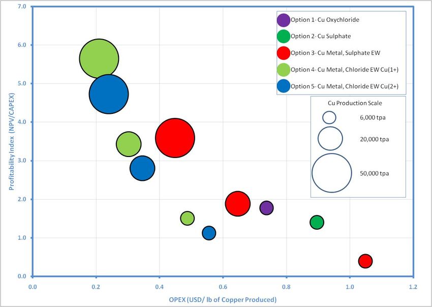
Table of Contents
1     Introduction .................................................................................................................................... 3
2     Intec Process Background ............................................................................................................... 4
    2.1      Halide Lixiviants ...................................................................................................................... 4
    2.2      Leaching Processes ................................................................................................................. 5
      2.2.1          Sulphides ......................................................................................................................... 5
      2.2.2          Oxides.............................................................................................................................. 6
      2.2.3          Arsenic Bearing Feedstocks ............................................................................................ 6
      2.2.4          Iron Residue .................................................................................................................... 6
      2.2.5          Leach Conditions Summary ............................................................................................. 7
      2.2.6          Leach Circuit Design ........................................................................................................ 7
      2.2.7          Co‐Current Leaching (Cupric System) ............................................................................. 8
      2.2.8          Counter‐Current Leaching (Cuprous System) ................................................................. 8
    2.3      Copper Recovery Options ....................................................................................................... 9
      2.3.1          Copper Halide Electrowinning ........................................................................................ 9
      2.3.2          Solvent Extraction of Copper from Halide Solutions .................................................... 10
      2.3.3          Copper Oxychloride Precipitation ................................................................................. 11
    2.4      By‐Product Credit Metals Recovery Options ........................................................................ 11
      2.4.1          Gold ............................................................................................................................... 12
      2.4.2          Silver .............................................................................................................................. 12
      2.4.3          Indium ........................................................................................................................... 12
      2.4.4          Bismuth ......................................................................................................................... 12
3     Intec Process Advantages ............................................................................................................. 13
    3.1      Intec Process vs. Smelters ..................................................................................................... 13
    3.2      Intec Process vs. Sulphate Hydrometallurgy......................................................................... 13
4     Intec Process Economics ............................................................................................................... 15
    4.1      Intec Process Economics vs. Competing Technologies ......................................................... 15
    4.2      Intec Process Economic Models............................................................................................ 16
5     Intec Process Environmental Advantages ..................................................................................... 18
    5.1      Life Cycle Analysis ................................................................................................................. 18

                                                                                                                                                           2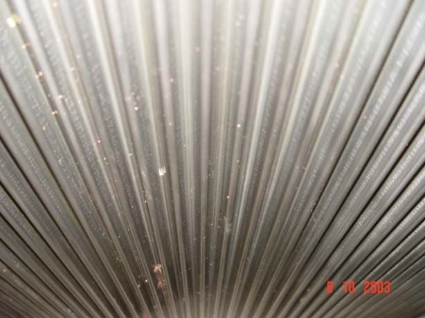
1 Introduction
The Intec Process is a family of patented hydrometallurgical technologies for the recovery of base
and precious metals from sulphide and oxide feedstocks. It is based on the use of halide (chloride,
bromide and iodide) chemistry to solubilise metals through the leaching process, followed by the
recovery of high purity metals by electrowinning or chemical salts.

This document summarises the application of the technology for recovery of copper and associated
co‐product or by‐product metals, and is divided into three main sections with a particular emphasis
on its comparison with existing copper recovery technologies. Firstly, the technical aspects of the
process are explained, especially the ability of the Intec Process to accommodate large variations in
feedstock with respect to feedstock mineralogy, metal content and project size. The second section
provides an economic summary at varying production rates including comparison with the
economics of competing technologies. Finally, the environmental benefits of the Intec Process are
also described.

                                                                                                   3
2 Intec Process Background
The patented Intec Copper Process was developed for the recovery of copper metal at LME Grade A
purity. Essentially, the process consists of leaching, purification and product recovery
(electrowinning or other); however the unit operations can be adjusted based on the feedstock
composition, quantity and location in order to optimise economic returns.

An example flowsheet of the process is shown in Figure 2‐1. Fewer or additional unit operations may
be required depending on feedstock characteristics.

                                                                 CARBON COLUMN
                                                                      FOR GOLD                                                                    GOLD BULLION
                                                                                                                                        FURNACE
                     LIMESTONE
      COPPER
   CONCENTRATE            LEACH                               LEACH                                         LEACH
  (P80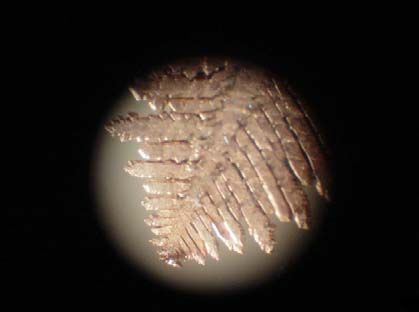
Bromide and iodide also enhance the stability of precious metals such as gold and silver. In some
applications of the Intec Copper Process, trace amounts of sodium iodide are selectively added to
enhance gold recovery.

The high metal leaching rates and efficiencies associated with the Intec Process leach create some
challenges for the physical plant. As such, the appropriate selection of materials of construction is
important to ensure longevity of equipment. All wetted parts of the plant are fabricated from high
performance plastics, or in some sections exotic alloys or titanium.

Reactors are typically constructed from comparatively inexpensive fibreglass reinforced plastic (FRP)
using Derakane 470‐300 resin, which permits continuous operation at 130 °C. The costs are similar
to or less than equivalent steel tanks. Various linings can be used where required for additional
protection, e.g. in high wear zones. Titanium or coated steel agitators have been successfully used,
with the final design specific for the mixing duties required. Piping is generally a mixture of PVDF,
FRP or random co‐polymer polypropylene depending on temperature and pressure duties.

The performance of these items of equipment has been systematically and successfully proven by
Intec at both laboratory and demonstration plant scales, along with ancillary items such as
instrumentation, heat‐exchangers, ducting, structural framework, and control systems.

2.2 Leaching Processes

There are two types of feedstock; metal‐sulphides (eg the common copper sulphide minerals CuFeS2,
CuS, and Cu2S) and metal‐oxides (eg CuO and Cu2O).

The Intec technology has been applied to a wide range of copper‐bearing minerals, and a summary
of the typical leach conditions is given in Table 2‐1. Notwithstanding the feedstock‐specific
limitations of particle size and mineral occlusion, typically 98% (95‐99.5%) extraction of copper is
achieved, and co‐extraction of credit metals (e.g. gold, silver, indium, bismuth, etc) is similarly high.

2.2.1   Sulphides

Metal sulphides are oxidised by sparging air to supply oxygen and the recycling of liquid anolyte
from the halide electrowinning cell (occasionally, with top up reagent acid), as shown in Reactions 1
and 2.

        4CuFeS2(s) + 5O2 + 20HCl J 4CuCl2 + 4FeCl3 + 8S(s) + 10H2O                 RXN 1

        2CuFeS2(s) + 5NaBrCl2 J 2CuCl2 + 2FeCl3 + 4S(s) + 5NaBr                    RXN 2

An oxidation‐reduction couple (eg. Cu+ Q Cu2+ + e‐) is employed to facilitate the transfer of oxygen as
shown in Reactions 3 and 4. Put simply, the copper acts as a ‘catalyst’ to maximise the efficiency of
oxygen uptake by the process liquor.

        4CuCl + O2(g) + 4HCl J 4CuCl2 + 2H2O                                       RXN 3

        CuFeS2(s) + 4CuCl2 J 5CuCl + FeCl3 + 2S(s)                                 RXN 4

As may be seen in Reactions 1 and 2, the sulphide component (S2‐) is only partially oxidised to
elemental sulphur (S), resulting in a significant reduction in the total oxygen requirement for the

                                                                                                       5
system. By comparison, sulphate‐based pressure oxidation technologies commonly oxidise sulphur
to sulphate (SO42‐).
2.2.2 Oxides
Metal oxides are leached with acid, which is normally added to the circuit according to Reaction 5. In
the case where mixed oxide and sulphide minerals are processed, acid can be generated in‐situ via
the oxidation of sulphur or sulphides (e.g. the oxidation of pyrite as shown in Reaction 6) and this
can be a cheaper alternative to purchasing fresh acid in certain situations.
CuO(s) + 2HCl J CuCl2 + H2O RXN 5
2FeS2(s) + 15NaBrCl2 + 4CaCl2 + 16H2O J 2FeCl3 + 4CaSO4(s) + 32HCl + 15NaBr RXN 6
Where acid is added directly to the process, sulphuric acid is purchased, as it is a lower cost reagent
than hydrochloric acid. The calcium chloride in the process liquor reacts with the sulphate to form
calcium sulphate and hydrochloric acid according to Reaction 7. Due to the high temperatures in the
circuit and the concentrated halide brine used in the Intec Process, the anhydrous form of calcium
sulphate (anhydrite) is precipitated, as opposed to the hydrated form (gypsum). The anhydrite is
highly crystalline and does not form scale on the process equipment, as is normally the case with
gypsum in sulphate‐based systems.
H2SO4 + CaCl2 J 2HCl + CaSO4(s) RXN 7
2.2.3 Arsenic Bearing Feedstocks
One of the major environmental reasons for selecting hydrometallurgical processing rather than
smelting for many copper concentrates is the presence of arsenic. Arsenic is a toxic metal which is
difficult to control in the off‐gas from smelter operations. As such, an upper limit of 0.5% arsenic in
the concentrate feedstocks is normally applied by smelters.
In the Intec Process leach circuit, arsenic is readily leached and re‐precipitated as highly crystalline
ferric arsenate according to Reactions 8 and 9. The crystalline ferric arsenate readily passes
conventional TCLP and MEP tests as a measure of environmental stability. In recognition of this, a
NSW EPA approval was granted to Intec in 1999/2000 for disposal of leach residue containing ferric
arsenate into conventional landfill. Feedstocks containing up to 10% arsenic have been successfully
treated by this method.
FeAsS + 7CuCl2 + 4H2O J FeCl2 + 7CuCl + S + H3AsO4 + 5HCl RXN 8
H3AsO4 + FeCl3 J FeAsO4(s) + H2O RXN9
2.2.4 Iron Residue
A potential issue for any process leach circuit is control and precipitation of solubilised iron. Many
technologies encounter significant difficulty with the physical handling, filtration and poor
environmental stability of precipitated iron wastes.
Leaching of copper minerals using the Intec Process is conducted in the pH range of 1‐2, where
leachable iron is re‐precipitated as hematite according to Reaction 10. The acid generated in this
reaction is re‐used to oxidise the copper cations as shown in Reaction 11.
62FeCl3 + 3H2O J Fe2O3(s) + 6HCl RXN 10
4CuCl + 4HCl + O2 J 4CuCl2 + 2H2O RXN 11
The hematite is crystalline and is thus readily filterable. Hematite is one of the most stable forms of
iron, and extensive testing has demonstrated that hematite product is environmentally stable, unlike
iron jarosites.
2.2.5 Leach Conditions Summary
The Intec Process technology has been applied to a wide range of copper‐bearing minerals at the
laboratory, pilot and/or demonstration plant scales. Table 2‐1 summarises the required leach
conditions for copper‐bearing minerals suitable for processing by the Intec Process.
Table 2‐1: Summary of Leach Conditions using the Intec Process
Mineral Formula Conditions Comments
Sulfides
Chalcocite Cu2S
75‐85 °C Rapid leaching behaviour
Covellite CuS
Chalcopyrite CuFeS2 85 °C Moderate leaching behaviour
Bornite Cu5FeS4
Enargite Cu3AsS4 Slow leach kinetics which can be enhanced by
95‐100°C
Tennantite Cu8As2S7 additives
Tetrahedrite 4Cu2S•Sb2S3
Oxides
Azurite 2CuCO3•Cu(OH)2
Cuprite Cu2O
>30 °C Rapid leaching behaviour
Malachite CuCO3•Cu(OH)2
Tenorite CuO
Other
Native Cu 75‐85 °C Rapid leaching behaviour
2.2.6 Leach Circuit Design
Two example leach circuit designs have been provided to showing the use of soluble copper in the
cupric (Cu2+) or cuprous (Cu+) state. A cupric‐based system would be appropriate to smaller projects
producing intermediate copper products or mixed‐technology projects, while a cuprous‐based
system would be appropriate for the production of high‐purity copper metal via electrowinning.
The simpler cupric system uses a single train of leach tanks, whereas the cuprous system uses a
three‐stage counter‐current circuit. A diagram of each circuit is shown in Figure 2‐2.
7Figure 2‐2: Block Diagrams of Co‐Current and Counter‐Current Leach Circuits
2.2.7 CoCurrent Leaching (Cupric System)
Cupric ions are ideal for the direct precipitation of copper oxychloride, or solvent extraction circuits
which can be linked to sulphate electrowinning or salt crystallisation units.
The leach conditions in the single train are highly oxidative in every tank, which affords the most
economical leach circuit. However, these savings must be weighed against the additional costs of
copper recovery from the cupric state if electrowinning is used as the final recovery step. This would
typically only be the case where copper was present as a by‐product to a higher‐value metal in the
feedstock, such as gold.
2.2.8 CounterCurrent Leaching (Cuprous System)
Cuprous ions are ideal for direct halide electrowinning, with about half the energy cost of
electrowinning from the cupric state (used in all other sulphate‐based copper electrowinning
technologies). As such, counter‐current leaching is appropriate for larger projects with dedicated
Intec Process electrowinning plants for production of high‐grade copper metal.
The leach conditions in the counter‐current circuit vary from tank to tank, to ensure that copper
exiting the leach is in the cuprous oxidation state. Additional cost is required for the thickeners, and
this also adds complexity for process control. However, at large production scales these costs are
offset by significant energy savings from the electrowinning of cuprous copper.
82.3 Copper Recovery Options
2.3.1 Copper Halide Electrowinning
Intec has developed a copper electrowinning cell specifically for cuprous (CuCl) and cupric (CuCl2)
systems. The cell is divided into two compartments via a porous diaphragm (conventional filter
cloth). The feed solution is directed to the cathode compartment, where metallic copper dendrites
are electrowon onto a patented corrugated titanium cathode (Reaction 12). The depleted solution
passes through the diaphragm into the anode chamber, where NaBrCl2 is generated at the anode
(Reaction 13). Some pictures of the titanium cathode (wiped and un‐wiped), copper dendrite, as well
as the conveyor are given in Figure 2‐3.
Cathode CuCl J Cu(s) + Cl‐ + 2e‐ RXN 12
Anode NaBr + 2Cl‐ + 2e‐ J NaBrCl2 RXN 13
Overall 2CuCl + NaBr J Cu(s) + NaBrCl2 RXN 14
Figure 2‐3: (TOP LEFT) Titanium corrugated cathode, (TOP RIGHT) Dendrite, (BOTTOM LEFT) Un‐wiped titanium cathode,
(BOTTOM RIGHT) Copper dendrites being removed from the EW cell by conveyor belt
The sodium bromo‐chlorine complex called Halex TM is a dissolved species with a low vapour
pressure. Halex behaves like chlorine gas in terms of oxidation power and chemistry, but with
obvious considerable handling advantages compared to a gas. It has a potential of around +1000 mV
(vs Ag/AgCl) and is highly reactive. As a liquid, the oxidant is easily recycled to the leach circuit,
where it is more easily utilised than a gas. Halex enhances the leaching of refractory minerals, which
often host gold.Importantly, the Halex species is unique to the Intec Process, being derived from the use of mixed‐
halide lixiviants. This intellectual property is secured by over two hundred international patents in
seven patent families that are constantly being updated as part of an ‘evergreening’ strategy.
Intec has operated a number of cells ranging from laboratory scale to the full commercial 1 tonne
per day scale. Larger plants would use multiples of the 1 tonne per day cell. The nominal operating
conditions are summarised in Table 2‐2.
Table 2‐2: Summary of Parameters for Copper Electrowinning Using the Intec Cell
Parameter Value Comment
Current Density 500‐1000 A/m2 Average in sulphate EW is 400 A/m2
Cell voltage 2.4‐3.2 V
Cell efficiency >98 %
Metal Purity LME A Grade
Electrodes per bath 32
Cathode dimensions 1.57 x 1 m
The key advantages of the Intec Process cell compared to copper‐sulphate electrowinning cells are
summarised below:
‐ The Intec Process copper dendrites are removed in‐situ using a wiper mechanism and a
conveyor belt. This eliminates the cost of cathode removal and stripping, allowing
continuous production;
‐ Three times the average current density of a sulphate cell is used in the Intec Process,
thereby significantly reducing the overall tankhouse foot print. The copper production rate is
up to eight times that of a conventional sulphate cell;
‐ The Intec Process cell can be fed with cuprous (Cu+) ions, thereby reducing the overall
energy requirements;
‐ The oxidant (HalexTM) generated at the anode is re‐used in the leach circuit, whereas the
oxygen from the sulphate cell anode is wasted to the atmosphere. This also means that the
electrical energy applied to the cell is fully recovered as copper metal and leach reagent.
The copper dendrites are washed and converted to oxygen‐free copper wirerod, which attracts a
premium of typically 4‐8% over LME A grade cathodes. Intec has successfully drawn 8mm wirerod,
produced from electrowon copper dendrites, to 0.1mm magnet wire, which meets normal wire
standards.
For some projects (typically those of small scale), economic considerations dictate that a cupric leach
is preferred. The electrowinning cell can be operated using Cu2+ ions, with the only detrimental
impact being a higher energy demand.
2.3.2 Solvent Extraction of Copper from Halide Solutions
An alternative to the direct production of metallic copper by electrowinning in the Intec Process is
the use of solvent extraction to selectively extract the copper into a separate process stream.
Over the last 30‐40 years, copper solvent extraction followed by electrowinning has gained a 20%
market share of the production methods for copper metal.
Most of the solvent extraction reagents contain oximes and are well developed and optimised to
transfer cupric ions (Cu2+) from a sulphate system, through the solvent. On the other hand, in the
concentrated halide brines used by Intec, copper is complexed as a negative anion such as CuCl2‐,
CuCl32‐, CuCl3‐, and CuCl42‐, hence other types of reagents must be used.
10In circuits where cuprous (Cu+) is the major form of copper, tri‐butyl‐phosphate is used. Care must
be taken to ensure that the copper is not oxidised and (enclosed) pulsed columns are applied in
these circumstances. The entire copper‐chloride complex is transferred according to Reaction 15.
The stripping solution is copper‐depleted catholyte from the halide electrowinning cell.
H2(CuCl3) + nTBP J nTBP.H2(CuCl3) RXN 15
In circuits where cupric (Cu2+) is the major form of copper, 7‐(4‐ehtyl‐1‐methylocty)‐8‐
hydroxyquinoline is used. This reagent is capable of loading both cationic and anionic forms of
copper as shown in Reactions 16 and 17. The loaded solvent is stripped with water to remove the
halide anions, and then with acid to recover the copper cations. Using this mechanism, it is possible
to transfer copper from a halide into a sulphate matrix for copper electrowinning or crystallisation of
copper sulphate pentahydrate.
2NROH + Cu2+ J (NRO)2Cu + 2H+ RXN 16
2HORNHCl + CuCl42‐ J (HORNH)2CuCl4 + 2Cl‐ RXN 17
2.3.3 Copper Oxychloride Precipitation
For small scale projects, the most economical method for recovering copper from a concentrated
halide solution is to precipitate copper oxychloride using limestone, as shown in Reaction 18. The
copper must be present as the cupric state, as cuprous ions are stable up to a pH of 6‐6.5,
necessitating the use of more expensive lime.
4CuCl2 + 3CaCO3 + 3H2O J 2Cu2(OH)3Cl + 3CaCl2 + 3CO2 RXN 18
Copper oxychloride is widely used as a fungicide and also competes against copper sulphate
pentahydrate as an animal feed supplement. It commands a value of between 85‐95 % of LME for
the contained copper. Unfortunately the niche market limits the applicability of this option to small‐
scale production.
A convenient method for reprocessing copper oxychloride is to use conventional oxime solvent
extraction reagents (e.g. ACORGA 5640). The precipitate is releached in acid, with the dissolved
chloride limited to 1 M. The cupric cations are loaded onto the solvent and stripped with hydrogen
cations. In this fashion the copper can be transferred to a conventional sulphate electrowinning
circuit for recovery. This technique is highly applicable to projects where existing sulphate
processing infrastructure is available.
2.4 ByProduct Credit Metals Recovery Options
The process steps required to recover by‐product metals such as gold, silver, indium and bismuth
can vary significantly, depending on the concentration of the metals in the feedstock and their
relative value to any particular project.
Where the by‐product contents and/or values are comparatively low, the chosen recovery methods
will be simpler, producing lower‐grade products at lower operating cost to maximise overall
profitability. Conversely, where the by‐product contents and/or values are comparatively higher,
there is value in using more sophisticated techniques to recover higher‐value products, in many
cases in metallic form.
11As the methodology can vary quite significantly based on the individual project needs, Section 2.4
provides only a rough guide to the process options available for by‐product metal recovery.
2.4.1 Gold
Gold recovery from Intec Copper Process leach liquors is achieved using activated carbon or ion‐
exchange resins in packed columns. These columns are contacted with clear leach solution
advancing from the cupric thickener, where the oxidation‐reduction potential is sufficient to
maintain the gold in solution.
The activated carbon can be saturated with gold and then ashed to recover gold metal. Alternatively
the loaded activated carbon is stripped using conventional cyanide or thiourea reagents and the
eluted gold is electrowon. The eluted carbon is then reactivated as required, and returned to the
process. Test results have shown that re‐activation is not required for at least five cycles. The latter
route is also applicable to ion‐exchange resins.
2.4.2 Silver
The liquor exiting the gold recovery stage (or directly exiting the leach, if gold recovery is not
required) is advanced to another series of columns containing selective silver adsorption resins
developed primarily for the Intec Process. The loaded silver is stripped using acid, with the silver
precipitated as a chloride for direct sale or smelted to produce silver metal. The barren adsorbent is
returned to the process.
For solutions containing cuprous ions, i.e. when a counter‐current leach design is used, the silver is
recovered using copper amalgamation promoted by trace mercury. A stoichiometric amount of
reducing agent is added to the solution, such as copper dendrites from the electrowinning cell, to
control the potential of the solution.
2.4.3 Indium
Indium in the copper leach processes is recovered directly using ion‐exchange resins in packed
columns or is precipitated to produce an indium‐rich cake for further processing. The feed stream
must be depleted of Fe3+ and Zn2+ ions, which compete for the active sites on the resin. The loaded
resin is eluted with acid and the eluted indium is electrowon to produce high purity metal or
crystallised to produce indium salts. The eluted resin is recycled to the process.
2.4.4 Bismuth
Bismuth recovery in the copper leach processes is very similar to indium recovery, where bismuth is
recovered directly using specialty adsorbents in packed columns or is precipitated to produce a
bismuth‐rich cake for further processing. The loaded adsorbent is eluted with acid and the eluted
bismuth is electrowon to produce high purity metal or crystallised to produce bismuth salts. The
eluted resin is recycled to the process.
123 Intec Process Advantages
The world’s supply of primary copper is produced by technologies that are solely pyrometallurgical
in nature, or solely hydrometallurgical, or more frequently a mixture of the two. This section
compares the Intec Process to the most common industrial smelting (pyrometallurgical) and
hydrometallurgical processes.
3.1 Intec Process vs. Smelters
The pyrometallurgical treatment processes used in smelters for the production of base metals
(generally from sulphide ores) have a number of well‐established disadvantages when compared to
hydrometallurgical processing:
‐ High unit capital costs which become economically feasible only at very large scale. As such,
smelters tend to be centrally located on rail, road and/or port transport routes, accepting
feedstocks from multiple mines, in many cases transporting the feedstocks for thousands of
kilometres prior to processing. Smelters are only built at minesites for very large projects;
‐ High‐grade and metal‐specific concentrate feeds are required, which tend to detract from
the recovery of base metals from the ore into the concentrate (smelter feedstock);
‐ The handling of many common metallic and other contaminants in base metal concentrates
is difficult and either pollutes the air with sulphur dioxide and other contaminants such as
arsenic and lead, or incurs the high costs of pollution containment;
‐ Sulphuric acid is produced as a by‐product from sulphur dioxide emission control. Its value is
highly variable depending on location and may even be negative.
The Intec Process has significant advantages over existing smelting technology. These advantages
are both economic and environmental and include:
‐ Significantly lower operating and capital costs;
‐ Smaller scale projects are economically viable;
‐ Low grade and contaminated concentrates are tolerated;
‐ No noxious gases are produced; and
‐ Sulphur is converted from the leachable minerals into its elemental from, from which it may
be recovered if required.
3.2 Intec Process vs. Sulphate Hydrometallurgy
Many attempts have been made to overcome the various economic and environmental problems
associated with copper smelting, mostly via the development of hydrometallurgical processes in the
sulphate medium. These sulphate‐based technologies share a number of characteristics which
impact on their economic and environmental performance:
‐ All contain an SX/EW step meaning that their economics can never be better than the
economics of the SX/EW step;
‐ All require a secondary leach step to recover precious metals from their residues (precious
metals are insoluble in sulphate systems), which are processed separately at additional cost.
This is a significant factor, as over 80% of copper concentrates contain economically
recoverable precious metals;
‐ Cyanidation is required to recover precious metals from residues. This is an important
economic and environmental consideration;
13‐ Residues may be expected to contain jarosites which are physically problematic to handle,
and are environmentally unstable.
The main sulphate‐based copper hydrometallurgy processes that have reached the advanced pilot
stage are set out below:
‐ The Total Pressure Oxidation Process or PLACER Process (ultra high‐temperature/pressure
oxidation of concentrate followed by SX/EW for copper recovery);
‐ The Activox Process (ultra fine grinding followed by moderate‐temperature/pressure
oxidation of concentrate followed by SX/EW for copper recovery);
‐ The Albion Process (ultra fine grinding followed by atmospheric pressure ferric leach
followed by SX/EW for copper recovery);
‐ BioCOP and Bactech Processes (direct bacterial leaching processes followed by SX/EW for
copper recovery);
‐ The Dynatec Process (high temperature pressure leaching of concentrates with dispersant
coal addition followed by SX/EW for copper recovery);
‐ The CESL Process (high temperature/pressure oxidation leach with added chloride followed
by SX/EW for copper recovery);
‐ AARL/UBC (high temperature/pressure oxidation leach with added surfactants followed by
SX/EW for copper recovery); and
‐ Galvanox (low temperature leach)
Few of these technologies have progressed to commercial‐scale application.
As distinct from the above sulphate‐based hydrometallurgical processes, the Intec Copper Process as
well as the HydroCopper Process and Sumitomo Copper Process are based on halide (mixed
chloride/bromide) chemistry. Intec’s unique halide chemistry facilitates the paradigm shift that is
essential to the commercially successful transformation of the copper concentrate processing
industry economics.
Intec’s advantages over the sulphate‐based hydrometallurgical processes variously include;
‐ Atmospheric‐pressure, low‐temperature leach conditions
‐ Low cost materials of construction
‐ Direct recovery of precious metals
‐ No requirement for solvent extraction
‐ No requirement for pure oxygen
‐ Copper EW from the cuprous (one electron) state rather than the cupric (two electron)
state, greatly reducing energy consumption
‐ Regeneration of the lixiviant at the anode of the EW cell in soluble form for return to the
leach circuit rather than the wastage of anodic energy by the bubbling of pure oxygen to the
atmosphere in the sulphate system
‐ Significantly lower operating and capital costs
‐ Economic viability down to smaller‐scale capacity levels
‐ Production of an environmentally acceptable residue
‐ Lowest energy consumption
‐ No liquid effluents.
144 Intec Process Economics
The Intec Process has a considerable range of advantages relative to smelting and other
hydrometallurgical processes, of which the most compelling advantage is its low economic cost. This
section provides an economic comparison of the Intec Process to other existing and developing
copper processing technologies. Additionally, a range of economic models have been prepared to
summarise and compare various project scenarios.
4.1 Intec Process Economics vs. Competing Technologies
The economic comparison contained in the below figures is the primarily derived from independent
analyses commissioned by Intec over a number of years, plus some of Intec’s enquiries and
calculations.
The comparison in Figure 4‐1 is based on the development of conceptual mass balances for each of
the processes reviewed, from which operating and capital costs were estimated in a 2003 study. This
approach ensures a consistent basis for comparison and includes the following key assumptions:
‐ Plant capacity of 100,000 tpa copper
‐ Treatment of a 25% copper concentrate feed containing no precious metals
‐ Power cost of 6.25US¢/kWh.
Intec has then incorporated into this analysis the capital and operating costs of a precious metals
recovery circuit for all of the hydrometallurgical processes reviewed. The need for the separate
recovery of precious metals by other hydrometallurgical processes is important, as approximately
80% of the world production of copper concentrates contain economically recoverable quantities of
precious metals.
The comparison assumes on‐site production costs and therefore excludes marketing and freight
costs and acid credits, whilst the cost of acid neutralisation is included. It should also be noted that
these calculations incorporate an additional step for the melting and casting of the Intec Copper
Process dendritic product into ingot, to give a conservative and equal basis for comparison.
250% 300%
% of Intec Capex
250%
% of Intec Opex
200%
200%
150%
150%
100%
100%
50% 50%
0% 0%
Intec Smelter Dynatec Activox CESL Biox Total Intec Biox Activox CESL Dynatec Total Smelter
POx POx
Processes Processes
Figure 4‐1: Comparison of Operating and Capital costs at 100,000 tpa Copper plant capacity for various process
technologies
154.2 Intec Process Economic Models
More recent economic models for five Intec Copper Process production options are presented,
covering three different production scales (6,000, 20,000 and 50,000 tonnes of copper per annum);
Option 1: Production of Copper Oxychloride
Option 2: Production of Copper Sulphate Pentahydrate
Option 3: Production of Copper metal via a sulphate electrowinning process
Option 4: Production of Copper metal via a chloride cuprous (Cu+) electrowinning process
Option 5: Production of Copper metal via a chloride cupric (Cu2+) electrowinning process
The following key assumptions have been made to produce these models;
‐ Copper price of AUD$ 7,000 /tonne
‐ Discount rate of 10%
‐ Project life of 10 years
‐ Concentrate cost not allowed for
‐ The plant is located in Australia and so Australian reagent, utility and labour rates apply.
It should be noted that, to be conservative, no credit metals such as silver or gold are included in
these estimates. Credit metals can greatly increase revenues depending on which process option is
selected. Similarly, the integration of the plant into existing SX/EW plants would significantly reduce
capital cost for some of these options.
Figure 4‐2 provides a graphical means by which process options can be compared at different
production scales in terms of their profitability index (project NPV divided by initial capital
investment) and operating cost/tonne of produced copper.
Figure 4‐2: Comparison of Profitability Index (NPV/CAPEX) versus OPEX for Five Copper Products at 6,000, 20,000 and
50,000 tpa Scales
16It can be seen that for small scale production (6,000 tpa), intermediate copper production (copper
oxychloride or copper sulphate pentahydrate, Options 1 and 2) or cuprous (Cu+) electrowinning
would be preferable. The selection of process option would be dependent on market conditions
(especially product demand and energy costs) in the respective plant region.
For larger scale production (>20,000 tpa), copper electrowinning becomes preferable. It should be
noted that although the precipitation of salts at large scale still offers good profitability indices,
global demand for those products is limited and hence the revenue figures may not be as easily
achievable. Large‐scale copper salt production has therefore not been included in Figure 4‐2. At
20,000 tpa scale, the profitability index for both Intec Process copper metal producing options is at
or greater than 2.8. At 50,000 tpa scale, the index is 4.7 – 5.6, and this is where the economic
benefits of large scale operations are realised.
175 Intec Process Environmental Advantages
There are numerous environmental advantages to the Intec Process when compared to competing
pyrometallurgical and hydrometallurgical technologies. Some of these have already been explored,
such as the successful treatment of arsenic containing feedstocks and the environmental stability of
the iron residues. This section details a life cycle analysis of the Intec Copper Process in comparison
to a number of competing copper processing technologies.
5.1 Life Cycle Analysis
Intec commissioned a Life Cycle Analysis (LCA) of the Intec Copper Process in 2001. This study was
conducted by the Commonwealth Scientific and Industrial Research Organisation (CSIRO) using
published data for the competing technologies, as well as information provided by Intec Ltd for the
Intec Process.
The base case of the CSIRO LCA compared the Intec Copper Process with flash smelting, four
pressure oxidation hydrometallurgical processes, and two biohydrometallurgical processes. Using a
system boundary incorporating mining, concentrate production, and metal production & refining,
the boundary for all processes was an equivalent ‘cradle‐to‐gate’ for copper metal production. The
initial production of a 25% copper concentrate (30% S, 100g/t Ag, 10g/t Au) as uniform feedstock to
the process was assumed, with the electricity used by the processes being generated from black coal
at 35% efficiency.
As an Intec Copper Process plant would most likely be located at a mine site to optimise the
advantages associated with the Process’ flexibility of scale, improved ore‐to‐metal recoveries
through the production of lower grade concentrates at the mill, and improved economics through
avoiding smelter charges and penalties, it was assumed that no transport would be required for the
Intec Copper Process. The same assumption was used for the other hydrometallurgical processes. It
is worth noting, however, that the Intec Process benefits of most of these optimisation measures
(particularly the higher ore‐to‐metal recoveries) were excluded from the analysis in the common
assumption of the production of a 25% copper concentrate.
Given that approximately half of the world’s copper production occurs at integrated smelters
(presumably involving minimal transport of concentrate), while the other half is traded on the
custom market (presumably involving long transport distances including road or rail and possibly
ship), a conservative assumption of 500km transport by rail was assumed for smelting in the base
case.
After collating all process information from the published data, the figures were sent by the CSIRO to
the appropriate companies for review, and comments or changes incorporated where applicable.
Within the context of the assumptions used for the LCA, the seven processes were compared for
Total Energy Consumption (TEC, MJ/kg‐Cu), Global Warming Potential (GWP, kg‐CO2(eq)/kg‐Cu) and
Acidification Potential (AP, kg‐SO2(eq)/kg‐Cu).
The cradle‐to‐gate system boundary applied encountered one problem in that the Intec Copper
Process produces LME Grade A copper in dendritic form, while the other hydrometallurgical and
smelting processes considered produce copper in pure cathode form. It is unlikely that the Intec
Copper Process product would be cast into ingot without any form of value‐adding. Rather, the
product would most likely be melted and cast into product forms from the molten state. Either way,
this leaves a disparity between the products being compared. As no resolution for this was possible,
the conservative assumption that the Intec Copper Process product would be melted and cast into
ingot was used.
18As shown in Figure 5‐1, the base case conclusion from the CSIRO LCA was that the total energy
requirement for the Intec Copper Process is 36% lower than the average for pressure oxidation
hydrometallurgical processes and 41% lower than the average for biological processes, but 5.9%
higher than that for smelting when using black coal. However, using hydro to generate electricity,
the Intec Process impact was lower than that of smelting. The differences are even more marked for
Global Warming Potential (Figure 5‐1).
With respect to the differences between the Intec Copper Process and flash smelting, the result is
similar to expectations, because a significant proportion of the energy obtained in smelting is
obtained from the burning of sulphur minerals instead of carbon fuels to produce the smelters’
energy. This creates large amounts of sulphur dioxide, which if uncontrolled would yield significant
acid rain, but reduces the apparent total energy consumption by smelters. Even incorporating
smelter gas controls, the production of this sulphur dioxide is the reason for the marked advantage
for the Intec Copper Process for Acidification Potential (Figure 5‐2). Effectively, smelters trade one
form of environmental impact (GWP) for another (AP).
While both processes use electricity, the largest single source of electricity consumption associated
with all hydrometallurgical processes is the electrowinning of metals from solution. As may be seen
in Figure 5‐1, the effect of changing the fuel used for power generation changes the ratios for Total
Energy Consumption and GWP. Using either natural gas or hydroelectricity instead of black coal, the
Intec Copper Process maintains and extends its advantages over pressure oxidation and biological
hydrometallurgical processes, while reducing the impact versus flash smelting. Using hydroelectric
power, the Intec Copper Process offers the lowest impacts for Total Energy Consumption, Global
Warming Potential and Acidification Potential under the set of assumptions employed by the CSIRO
LCA.
Figure 5‐1: (LEFT) CSIRO LCA Total energy results: Base case and hydroelectric power case and (RIGHT) CSIRO LCA Global
Warming Potential (GWP) results: Base case, natural gas and hydroelectric power cases
0.060
0.050
AP (kg SO2-eq/kg Cu
0.040
0.030
0.020
0.010
0.000
Intec POx Average Bio Average Flash Smelting
Black Coal (Base Case) Natural Gas
Figure 5‐2: CSIRO LCA Acidification Potential (AP) results: Base case and natural gas power case
19The advantages of the Intec Copper Process over smelting become even more pronounced when
lower concentrate grades are considered. Noting that flash smelting may not even be economic at
lower grades, the total energy consumption associated with Intec Copper Process and flash smelting
treating a 20% concentrate was calculated to be almost identical at 51.4MJ/kg‐Cu and 51.5MJ/kg‐Cu,
respectively. At 15% copper in the concentrate, where few if any smelters could operate
economically, the results were 52.1 and 58.5MJ/kg‐Cu, respectively. These results include the
conservative assumptions of the melting of the Intec Copper product and casting as ingot, and the
use of black coal power generation.
Given that higher metal recoveries may often be obtained at the mill by the production of lower
grade concentrates, and given the greater flexibility of scale offered by the Intec Copper Process, the
Process offers several notable advantages over smelting to the miner:
‐ Lower TEC, GWP and AP than smelting when using either lower grade concentrates or
alternate fuel sources to black coal for power generation;
‐ Fewer environmental impacts associated with the loss of copper minerals to the mill tailings;
‐ Greater project returns associated with higher ore‐metal recoveries;
‐ Greater resource utilisation associated with the ability to lower the ore cutoff grades feeding
the mill. They may also extend mine life; and
‐ By operating at the mine site, the Intec Copper Process offers smaller mines the opportunity
to contain the value associated with metal production from concentrate within the mine
gate, rather than passing it on to smelters.
20You can also read