The Onera elsA CFD software: input from research and feedback from industry - Cambridge University ...
←
→
Page content transcription
If your browser does not render page correctly, please read the page content below
Mechanics & Industry 14, 159–174 (2013)

         c AFM, EDP Sciences 2013                                                                                                                             Mechanics
         DOI: 10.1051/meca/2013056                                                                                                                           &Industry
         www.mechanics-industry.org

         The Onera elsA CFD software: input from research and feedback
         from industry
         Laurent Cambiera , Sébastien Heib and Sylvie Plot
         Onera – The French Aerospace Lab, 92322 Châtillon, France

                        Received 31 January 2013, Accepted 11 April 2013

                        Abstract – The Onera elsA CFD software is both a software package capitalizing the innovative results
                        of research over time and a multi-purpose tool for applied CFD and multi-physics. The research input
                        from Onera and other laboratories and the feedback from aeronautical industry users allow enhancement
                        of its capabilities and continuous improvement. The paper presents recent accomplishments of varying
                        complexity from research and industry for a wide range of aerospace applications: aircraft, helicopters,
                        turbomachinery...

                        Key words: Navier-Stokes / aerodynamics / aircraft / helicopter / turbomachinery

         1 Introduction                                                                            involves input from other research laboratories and feed-
                                                                                                   back from aeronautical industry. The objective of the pa-
             For about 15 years at Onera, the elsA software is si-                                 per is to show recent outstanding accomplishments both
         multaneously a basis for Computational Fluid Dynam-                                       from the research side and from the industry side.
         ics (CFD) research, a software package capitalizing on
         the innovative results of research over time, a tool al-
         lowing investigation and understanding of flow physics,                                    2 General description of elsA
         and a multi-purpose tool for applied CFD and multi-
         physics [1–5]. The range of aerospace applications covered                                    First, let us briefly recall the main features of the elsA
         by elsA is very wide [6]: aircraft, helicopters, tilt-rotors,                             software (see a more detailed overview in [5]). The elsA
         turbomachinery, counter-rotating open rotors (CROR),                                      multi-application CFD simulation platform deals with
         missiles, unmanned aerial vehicles (UAV), launchers. . .                                  internal and external aerodynamics from the low sub-
             As a matter of fact, the aerodynamic analysis and                                     sonic to the high supersonic flow regime and relies on
         design in aerospace today require high levels of accu-                                    the solving of the compressible 3-D Navier-Stokes equa-
         racy and reliability which result from studies in several                                 tions. elsA allows the simulation of the flow around mov-
         domains: physical modelling, numerical methods, soft-                                     ing deformable bodies in absolute or relative frames. A
         ware engineering, efficiency on rapidly evolving hardware                                   large variety of turbulence models from eddy viscosity
         and extensive validation by comparison with experimental                                  to full differential Reynolds stress models (DRSM) are
         databases. The capitalization of various research results                                 implemented in elsA for the Reynolds averaged Navier-
         in the elsA multi-purpose code allows in the first place the                               Stokes (RANS) equations [7, 8]. Laminar-turbulent tran-
         sharing of common CFD features for simulating external                                    sition modelling relies either on criteria, or on solving ad-
         flows around airframes or internal flows in turbomachin-                                    ditional transport equations [7]. Various approaches for
         ery. In the second place, it allows the selection over the                                Detached Eddy Simulations (DES) [9,10] and Large Eddy
         wide range of capabilities, of the features which are best                                Simulations (LES) are also available.
         suited to the application, since there is no universal CFD                                    Complex geometrical configurations may be handled
         method answering all of the problems.                                                     using high flexibility techniques involving multi-block
             The research studies, software development and vali-                                  structured body-fitted meshes: these techniques include
         dation activities, dealing with elsA, rely on a project ap-                               patched grid and overset capabilities (Chimera tech-
         proach necessary to cope with the complexity of today’s                                   nique [11, 12]). From this initial multi-block structured
         CFD. This project approach is coordinated by Onera and                                    meshing paradigm, elsA is presently evolving toward a
                                                                                                   quite complete multiple-gridding paradigm including the
           a
               Corresponding author: Laurent.Cambier@onera.fr                                      local use of unstructured grids [13–15] in some blocks of

                                                                       Article published by EDP Sciences
Downloaded from https://www.cambridge.org/core. IP address: 46.4.80.155, on 30 Sep 2021 at 04:23:41, subject to the Cambridge Core terms of use, available at https://www.cambridge.org/core/terms
. https://doi.org/10.1051/meca/2013056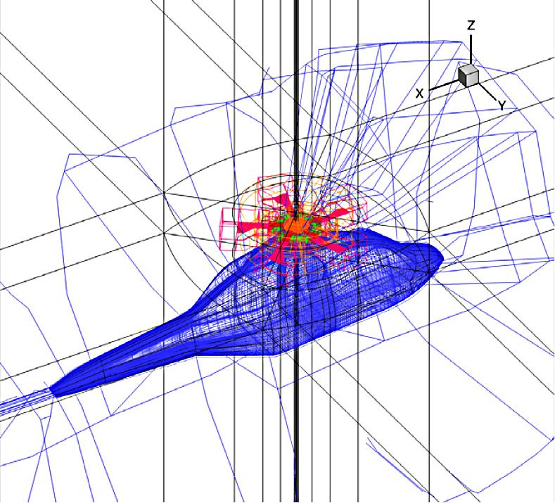
160                                           L. Cambier et al.: Mechanics & Industry 14, 159–174 (2013)

       a multi-block configuration as well as adaptive Cartesian                                  present some real-world applications from the main in-
       grids [11, 12].                                                                           dustry users. Then, we will show results from Onera and
           The system of equations is solved by a cell centered                                  research partners, mostly illustrating prospects for future
       finite-volume method. Space discretization schemes in-                                     use.
       clude classical second order centered or upwind schemes
       and higher order schemes. The mostly used integration
       of the semi-discrete equations relies on a backward Euler                                 4 Results from industry users
       technique with implicit schemes solved by robust LU re-
       laxation methods. The convergence is accelerated by the                                      This section presents some examples of the use of elsA
       use of multigrid techniques for steady flows. The implicit                                 by three of our main industry partners: Safran, Airbus
       Dual Time Stepping (DTS) method or the Gear scheme                                        and Eurocopter.
       is employed for time accurate computations.
           elsA also includes an “aeroelasticity module” [16, 17]
       offering a framework for aeroelastic simulations and an                                    4.1 Turbomachinery results
       “optimization module” for calculation of sensitivities by
       linearized equation solution or by adjoint solver tech-                                       Figure 1 provided by Snecma company (Safran group)
       niques [18, 19].                                                                          shows some elsA results for modern fans. The two curves
           elsA is based on an Object-Oriented (OO) design                                       illustrate the contribution of the Onera CFD software
       method and is coded in three programming languages:                                       (elsA in recent years) to the simultaneous progress of the
       C++ as main language for implementing the OO design,                                      efficiency of the conventional fans (more than 10 points
       Fortran for CPU efficiency of calculation loops, Python                                     in 30 years) and the reduction of the blade number (twice
       for the user interface. A good CPU and parallel efficiency                                  less blades). Examples of simulations are shown for a con-
       is reached on a large panel of computer platforms.                                        ventional fan, a counter rotating fan and a CROR.
                                                                                                     The elsA software has been strongly validated by On-
                                                                                                 era and Safran for various turbomachinery configurations
                                                                                                 and is today intensively used for design studies which
       3 Research partners and industry users                                                    rely for a part on isolated row simulations, and for the
                                                                                                 major part on multi-stage applications. Best practice on
           The development and the validation of the elsA soft-                                  space and time numerical schemes, turbulence and tran-
       ware benefit by inputs from research partners and feed-                                    sition modelling, boundary conditions have been defined
       back from industry users. By first considering the re-                                     through comparisons with experiment and with legacy
       search side, the Cerfacs organization (Toulouse) is an                                    code results. The design work includes studies on techno-
       important elsA partner since 2001 and has been par-                                       logical effects, such as rotating and non-axisymmetrical
       ticipating over the last decade to research studies and                                   platforms, mass flow injection or suction, casing treat-
       software development dealing in particular with mesh                                      ments, grooves, cooling holes.
       strategies [13], numerical methods [20–24] and CPU ef-                                        Figure 2 shows a typical result of flow simulations per-
       ficiency [25]. Other main research partners are the Fluid                                  formed by Snecma on a multi-stage configuration. The
       Mechanics and Acoustics lab (LMFA, École Centrale de                                     approximate steady flow calculations through multi-stage
       Lyon) [26] and Cenaero (Belgium) [27] for turbomachin-                                    machines are today usual in design process. In elsA, they
       ery flow simulation, and the Dynfluid lab (Arts et Métiers                                 rely on a specific steady condition based on azimuthal
       ParisTech) for high accuracy numerical schemes [28, 29]                                   averages, the mixing plane condition, to connect two
       (see Sect. 5 for activities about elsA by Cerfacs, LMFA,                                  consecutive rows. This type of simulation gives a quite
       Cenaero and Dynfluid). The Von Karman Institute also                                       good prediction of the overall efficiency of a machine,
       uses elsA for turbomachinery flow simulation (see the val-                                 even if of course it does not give any information on the
       idation study of the transport equation transition model                                  flow unsteadiness, as may be given by the more costly
       in Ref. [30]).                                                                            Reduced Blade Count technique and Phase-Lagged (or
           Whereas it is rather unusual for a CFD software pack-                                 chorochronic) method also available in elsA for time-
       age to deal both with external flows around aircrafts or                                   periodic flows [5].
       helicopters and with internal flows in turbomachinery,                                         The number of mesh points for the 4-stage low pres-
       elsA is today used as a reliable tool by Airbus for trans-                                sure turbine configuration of Figure 2 is about 10 mil-
       port aircraft configurations, by Safran group for turboma-                                 lion. Numerical settings for the steady flow simulation are
       chinery flow simulations and by Eurocopter for helicopter                                  the following: second order Jameson scheme, backward
       applications (see Sect. 4). Among other users, let us men-                                Euler implicit time integration scheme, LU-SSOR im-
       tion MBDA for missile configurations and Électricité de                                  plicit technique, multigrid convergence acceleration. Tur-
       France for steam turbine applications [31].                                               bulence modelling relies on Wilcox (k, ω) model. Con-
           A two-day workshop gathering simultaneously re-                                       verged solution is obtained on Snecma computer in less
       search partners and industry users is organized every                                     than one day. Figure 2 presents the flow field in the
       two years to share experience. The results presented in                                   complete 8-row computational domain. Numerical results
       the paper either are issued from the last elsA workshop,                                  show a good comparison with measured static pressure
       or correspond to more recent accomplishments. We will                                     on the vane walls. The comparison of the isentropic Mach

Downloaded from https://www.cambridge.org/core. IP address: 46.4.80.155, on 30 Sep 2021 at 04:23:41, subject to the Cambridge Core terms of use, available at https://www.cambridge.org/core/terms
. https://doi.org/10.1051/meca/2013056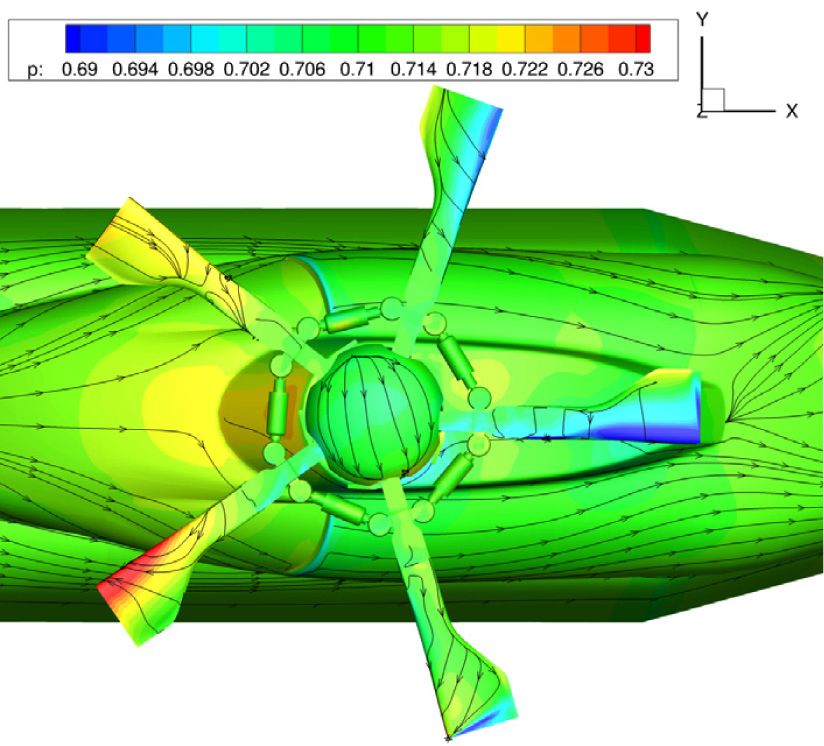
L. Cambier et al.: Mechanics & Industry 14, 159–174 (2013)                                                                  161

                                                                         Blade number

               Efficiency

                                                                                                                (a) Iso-absolute Mach number at mid-span

                      Potential
                      methods

                                    Design year
              (a) Evolution over time of efficiency and blade number

                                                                                                      (b) Wall static pressure (Δp = 2 000 Pa) on the hub and
                                                                                                      on the shroud : comparison with experiment

                                    Modern fan with 18 blades

                            Counter rotating fan with 10 + 14 blades

                                                                                                       (c) Isentropic Mach number on the wall of a distributor
                                                                                                       (mid-span): comparison with experiment.

                                                                                                   Fig. 2. Snecma results with elsA on a 4-stage turbine (cour-
                    Counter rotating open rotor with 12 + 10 blades                                tesy of Safran/Snecma).
              (b) Results of elsA simulations carried out by Snecma

         Fig. 1. Contribution of CFD to improvement of efficiency                                    of aerodynamic engineers of transport aircraft manufac-
         (courtesy of Safran/Snecma).                                                              turers. Navier-Stokes CFD has been introduced for many
                                                                                                   years in Aerodynamic Design and Data processes of Air-
                                                                                                   bus with the following objectives:
         number on one of the distributors for different span loca-
         tions (here shown at mid-span) is also satisfactory.                                        – quickly deliver more optimized aircraft components
             elsA software is also used by other turbomachinery                                        aerodynamic shapes;
         manufacturers of the Safran group: Turbomeca for heli-                                      – evaluate Reynolds effects, jet effects, ground effects by
         copter engines and Techspace Aero for fans and boosters.                                      extrapolating results known on an existing aircraft;
                                                                                                     – prepare, analyse and, if necessary, correct wind tunnel
                                                                                                       and flight tests.
         4.2 Transport aircraft results                                                            Airbus today uses elsA as its structured multi-block tool
                                                                                                   with various join types and Chimera overset grids. There
            CFD based on Navier-Stokes equations has today                                         has been a massive ramp-up of the use of Chimera tech-
         reached a maturity level in terms of accuracy, robustness                                 nique in daily production during the last few years.
         and efficiency, which makes it essential for the daily work                                 Thanks to this technique, control surface applications

Downloaded from https://www.cambridge.org/core. IP address: 46.4.80.155, on 30 Sep 2021 at 04:23:41, subject to the Cambridge Core terms of use, available at https://www.cambridge.org/core/terms
. https://doi.org/10.1051/meca/2013056
162                                           L. Cambier et al.: Mechanics & Industry 14, 159–174 (2013)

                                                                                                       Basic landing gear cavity               Additional internal spoiler

       Fig. 3. Pressure coefficient calculated by elsA for a generic
       aircraft in landing configuration with/without internal spoiler
       deployed (Onera calculation).
                                                                                                        Without internal spoiler                  With internal spoiler
       are now commonly realized with structured meshes.                                         Fig. 4. Landing gear cavity unsteady simulation – Effect of
       This overset technique also gives to Airbus plenty of                                     an internal spoiler – Iso-Mach contours (green: M = 0.2; red :
       opportunities to apply it in an easy and fast turnaround                                  M = 0.15; yellow : M = 0.1) at a given time (courtesy of
       manner: antenna on fuselage, wing tip effect, Vortex                                       Airbus).
       generators...
           Figure 3 proposed by Airbus shows the pressure co-                                    the drag optimization with lift kept constant allows a
       efficient field for a twin wing-mounted turbofan generic                                     drag reduction of about 3 drag counts. Figure 5 shows
       transport aircraft in landing configuration. Two calcula-                                  the evolution of the pressure coefficient distributions in 4
       tions carried out by the Applied Aerodynamics Depart-                                     sections for the initial and optimized wings.
       ment at Onera are represented on this unique figure: with-
       out deployment of the internal spoiler on the right, and
       with deployment of the spoiler on the left. The multi-                                    4.3 Helicopter results
       block mesh includes more than 140 blocks and more than
       33 million mesh points for the deployed configuration.                                         CFD simulation around helicopters is today possible
       This type of configuration is considered as very difficult                                   with a detailed representation of the geometry which in-
       to calculate with block-structured meshes. Thanks to the                                  cludes the rotor head with complete mechanism. One im-
       use of Cassiopée pre-processing tools [11, 32] delivered                                 portant objective of such simulation is to establish a drag
       with the elsA software suite, these calculations illustrate                               breakdown of the rotor head, element by element, in or-
       the possibilities of the Chimera technique to deal with                                   der to determine the most important contributors to the
       such configurations. These results are considered by Air-                                  total drag. Moreover, the effect of taking into account ro-
       bus of utmost importance for performance prediction of                                    tor head rotation in the CFD simulation is determined as
       the landing configurations.                                                                shown in Figure 6.
           Thanks to elsA Chimera features, Airbus is also able                                      Besides, this type of simulation is used for studying
       to simulate the unsteady flow in a representative shape                                    the tailshake phenomenon which corresponds to a modal
       of the landing gear cavity of a transport aircraft (Fig. 4).                              excitation of the structure of the rear parts of the heli-
       A first mesh is defined for the basic configuration includ-                                  copter (tail beam, tail plane, fin) by the wake of the upper
       ing four Chimera domains respectively for the cavity, for                                 parts of the helicopter (rotor head, chimney, engine cowl-
       the fuselage, for the wheel and pylon and for a triangle                                  ing). This type of study requires a good prediction, not
       added plate. Then, to study the influence of an internal                                   only of the aerodynamic field around the rotor head, but
       spoiler, which was proposed in order to reduce the rear                                   also of the wake location and conservation. Figure 7 shows
       door loads, a second Chimera mesh is defined by adding                                     the result of an unsteady elsA simulation carried out by
       to the first mesh an internal spoiler Chimera domain. The                                  Eurocopter in a 36 million point mesh on 85 processors. A
       second computation shows a high rear door load reduc-                                     second order in space numerical scheme is used. The tur-
       tion by putting an internal spoiler at the middle of the                                  bulence model is the Wilcox (k, ω) model with the SST
       cavity. The conclusion of Airbus on this type of simu-                                    correction.
       lation is positive on the ability of the Chimera strategy                                     The drag prediction and the tailshake simulation both
       to deal with complex landing gear configurations and to                                    require high quality matchings between Chimera blocks,
       quickly test additional element effect, as well as on the                                  a fine mesh in the region of the rotor head wake and high
       elsA features for simulating unsteady flows.                                               quality numerics. Whereas the elsA simulation today pro-
           Another elsA feature appreciated by Airbus is the full                                vides with an accurate drag prediction, further improve-
       adjoint for optimum design. Figure 5 shows a pilot op-                                    ment, such as the use of higher order schemes and inter-
       timization application done in full reverse mode. For a                                   polations, is necessary for a deeper understanding of the
       wing geometry parametrisation based on 179 variables,                                     tailshake physics.

Downloaded from https://www.cambridge.org/core. IP address: 46.4.80.155, on 30 Sep 2021 at 04:23:41, subject to the Cambridge Core terms of use, available at https://www.cambridge.org/core/terms
. https://doi.org/10.1051/meca/2013056
L. Cambier et al.: Mechanics & Industry 14, 159–174 (2013)                                                                  163

             (a) Iso-contours of the pressure coefficient on the opti-
             mized wing

                                                                                                             (a) Mesh of the helicopter with complete rotor
                                                                                                             head

            (b) Evolution of the Cp distributions in sections 1 to 4
            between initial wing and optimized wing

         Fig. 5. Pilot optimization application with elsA in full reverse
         mode (courtesy of Airbus).

                                                                                                        (b) Pressure isocontours and friction lines on the walls

                                                                                                   Fig. 7. elsA simulation around an helicopter with complete
                                                                                                   rotor head (courtesy of Eurocopter).

                                                                                                   (Spalart-Allmaras model, (k, ω) and (k, ε) families, (k, l)
                                                                                                   Smith model), more advanced turbulence models for
                                                                                                   RANS equations are studied and developed in elsA [7],
         Fig. 6. Drag breakdown given by an elsA simulation (courtesy                              such as the non-eddy viscosity EARSM (explicit algebraic
         of Eurocopter).                                                                           Reynolds stress) [8] and DRSM models. In order to deal
                                                                                                   with flows exhibiting strong unsteadiness and large sep-
                                                                                                   arated regions, LES, RANS/LES and DES [9, 10] tech-
         5 Results from Onera and research partners                                                niques are also an important elsA research topic. We
             This section presents results from Onera and research                                 present in this section two results of these advanced mod-
         partners in order to highlight advanced features on tur-                                  elling techniques.
         bulence modelling, mesh strategies, numerics and aeroe-
         lasticity.
                                                                                                   5.1.1 EARSM turbulence modelling for a turbine flow
                                                                                                         simulation (LMFA work)
         5.1 Modelling for turbulent flows
                                                                                                       This section presents the result of a simulation car-
            Whereas most of the design studies are done                                            ried out by LMFA (see Ref. [26] for another elsA sim-
         with a few one- or two-equation turbulence models                                         ulation by LMFA for a car turbocharger compressor).

Downloaded from https://www.cambridge.org/core. IP address: 46.4.80.155, on 30 Sep 2021 at 04:23:41, subject to the Cambridge Core terms of use, available at https://www.cambridge.org/core/terms
. https://doi.org/10.1051/meca/2013056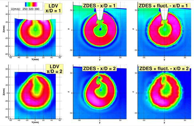
164                                           L. Cambier et al.: Mechanics & Industry 14, 159–174 (2013)

                                                                                                 Fig. 9. ZDES elsA simulation with the RFG technique: in-
                                                                                                 stantaneous Mach field at mid-span on the JEDI configuration
                                                                                                 (Onera simulation from [34]).

                                                                                                 model (above). On the prediction of losses (Fig. 8b), the
                                                                                                 comparison with experiment shows an improvement with
                                                                                                 the EARSM model. There is still an under-estimation of
                    (a) Iso-absolute Mach number at mid-span                                     the losses, which may be attributed to the unsteady rotor-
                                                                                                 stator interaction effects, which were not taken into ac-
                                                                                                 count in the steady simulation.

                                                                                                 5.1.2 Simulation of a jet with Zonal DES (Onera work)

                                                                                                     The DES-type approaches aim at combining the ac-
                                                                                                 curacy and low cost of the RANS model for attached
                                                                                                 boundary layers with the accuracy of the LES in sepa-
                                                                                                 rated regions and far from walls. These approaches are
                                                                                                 well adapted to installed double flux engine configura-
                                                                                                 tions since they allow for a deep analysis of turbulent
                                                                                                 structures inside mixing layers and of the interaction be-
                                                                                                 tween the pylon wake and the jet. The flow simulation
                                                                                                 presented here and detailed in [34] corresponds to a wall-
                (b) Losses in the low pressure distributor (Δx =                                 to-wall swept wing configuration equipped with a pylon
                Δy = 2%)                                                                         and an air supply stick, and studied in transonic flow con-
                                                                                                 ditions in the S3Ch wind tunnel of Onera Meudon. The
       Fig. 8. elsA simulation in a turbine: comparison between (k,                              modelling [34] relies upon evolutions of the Zonal DES ap-
       ω) and EARSM (courtesy of LMFA and Snecma).                                               proach [9,10] and upon a turbulent Random Flow Gener-
                                                                                                 ation (RFG) technique [35]. This RFG technique intends
                                                                                                 to represent the important turbulence levels which come
       The configuration provided by Snecma is composed of                                        from engines and which have a strong influence on the
       a high pressure turbine stage followed by the first row                                    jet development. The grid is composed of about 175 mil-
       of the low pressure turbine. Simulations with the (k, ω)                                  lion cells, mostly concentrated into the jet development
       model predict too small losses on the low pressure dis-                                   region thanks to the patched-grid technique. Numerics is
       tributor, in comparison with the experiment. The objec-                                   ordinary: second order in space centered scheme, second
       tive of the study of LMFA was to evaluate if a more ad-                                   order in time Gear scheme with Newton sub-iterations,
       vanced turbulence model would offer a better prediction.                                   implicit LU-SSOR technique in each sub-iteration.
       The considered turbulence model has been implemented                                          The computed instantaneous Mach flow field at mid-
       in elsA by the Department of Modelling in Aerodynam-                                      span (Fig. 9) shows the correct development of the shear
       ics and Energetics (DMAE) at Onera. It is an EARSM                                        layers as well as the complex interaction region between
       model [8] based on the (k, kl) two-equation model pro-                                    the pylon and the jets. Figure 10 presents a comparison
       posed a few years ago by DMAE. The turbulence closure                                     with the experimental averaged velocity fields of the re-
       is no more based on the Boussinesq assumption as for                                      sults of two ZDES simulations with and without turbu-
       the basic (k, kl) model, but on a non-linear relation be-                                 lence generation inside the engine. The simulation with
       tween the Reynolds tensor and the mean velocity gra-                                      the RFG technique is in a better agreement with exper-
       dients through the Wallin-Johansson expression of the                                     iment, but some discrepancies remain, mostly because of
       anisotropy tensor [33].                                                                   the still too low injected turbulence. Results on velocity
           Figure 8a shows a comparison of the flow fields ob-                                     fluctuations [34] confirm the importance of a correct esti-
       tained by the (k, ω) model (below) and the EARSM                                          mation of the turbulence rate of jets.

Downloaded from https://www.cambridge.org/core. IP address: 46.4.80.155, on 30 Sep 2021 at 04:23:41, subject to the Cambridge Core terms of use, available at https://www.cambridge.org/core/terms
. https://doi.org/10.1051/meca/2013056
L. Cambier et al.: Mechanics & Industry 14, 159–174 (2013)                                                                  165

                                                                                                   Fig. 11. elsA simulation of the M6 wing configuration: un-
                                                                                                   structured grid and static pressure iso-contours (Onera result
                                                                                                   from [15]).

         Fig. 10. Averaged velocity fields at x/D = 1 and 2. Left: LDV
         measurements – Middle: ZDES without RFG – Right: ZDES
         with RFG (Onera [34]).

         5.2 Mesh strategies

             Results presented in Section 4 show the complexity of
         the configurations (landing gear cavity, helicopter rotor
         head, turbomachinery technological effects) which may be
         handled with overset multi-block structured body-fitted                                    Fig. 12. elsA simulation in a shrouded stator : hybrid grid
         meshes. Nevertheless, it is very useful to have the ca-                                   (unstructured blocks in red) and flowfield (streamlines in the
         pability of using locally unstructured meshes in some of                                  cavity) (Onera result from [14]).
         the blocks where it would become too difficult to build a
         structured grid. Besides, structured Cartesian grid capa-
                                                                                                       The second configuration corresponds to a shrouded
         bilities are well adapted to high order spatial discretiza-
                                                                                                   stator. The hybrid grid remains structured around the
         tion and mesh adaptation, which in turn allows for better                                 blade and contains three additional unstructured blocks:
         capturing of off-body flow phenomena such as shear lay-
                                                                                                   two blocks located upstream and downstream of the blade
         ers and wakes. So, the objective of elsA is to progressively
                                                                                                   and one block corresponding to the cavity underneath
         offer a quite complete multiple-gridding paradigm provid-
                                                                                                   the hub. An unstructured grid generator is able to mesh
         ing the potential for optimizing the gridding strategy on
                                                                                                   the cavity by building only one block and in a shorter
         a local basis for each specific configuration. We present
                                                                                                   time than a multi-block structured generator. The Wilcox
         now two illustrations of this multiple-gridding evolution.
                                                                                                   (k, ω) model is used.

         5.2.1 Hybrid solver (Onera/Cerfacs work)                                                  5.2.2 Cartesian/curvilinear Chimera approach (Onera work)

             Over the past few years, a cooperative work between                                       CFD progress allows an increased use of CFD for
         Onera and Cerfacs [13–15] has allowed the extension of                                    aeroacoustics. The Blade Vortex Interaction (BVI) noise,
         the multi-block structured solver in elsA to an hybrid                                    typical of helicopter applications, has been selected here
         grid solver, in which structured (ijk-based) and unstruc-                                 to illustrate this topic. The challenge is to accurately cap-
         tured blocks may coexist within the same computational                                    ture the evolution of the blade tip vortex during the ro-
         domain. Structured zones may be kept for the sake of                                      tor revolution. The Chimera technique allows the overlap-
         efficiency and of accuracy in viscous layers, whereas un-                                   ping of a curvilinear multi-block blade grid and Cartesian
         structured zones may enable an easier mesh generation                                     background grids.
         and adaptation process.                                                                       Three grid resolution levels have been considered for
             Development and validation of the hybrid features                                     inviscid unsteady simulations performed with second or-
         in elsA are still in progress, but the two following re-                                  der scheme. In the finest mesh including 30 million cells,
         sults show that the elsA hybrid capabilities already al-                                  the wake is quite accurately captured with a strong vor-
         low turbulent flow simulations in parallel, for both ex-                                   tex intensity kept during 1.5 revolutions (only during 0.5
         ternal and internal aerodynamics. Figure 11 shows the                                     revolution with the coarse grid), which is necessary for
         static pressure iso-contours given by the simulation of the                               the interaction with the following blades (Fig. 13a).
         3D flow around the Onera M6 wing at M∞ = 0.84 and                                              The evolution of the sectional lift coefficient Cz M 2 at
         α∞ = 3.06◦ . The grid is composed of 32 unstructured                                      r/R = 0.87 on the advancing side (Fig. 13b) shows that
         blocks and the simulation is carried out on 32 processors.                                the amplitude and the phase of all simulations are quite
         The Spalart-Allmaras turbulence model is used.                                            good with the finest mesh (no BVI oscillation is simulated

Downloaded from https://www.cambridge.org/core. IP address: 46.4.80.155, on 30 Sep 2021 at 04:23:41, subject to the Cambridge Core terms of use, available at https://www.cambridge.org/core/terms
. https://doi.org/10.1051/meca/2013056
166                                           L. Cambier et al.: Mechanics & Industry 14, 159–174 (2013)

                                                                                                 5.3.1 RBC schemes for the flow simulation in a turbine
                                                                                                       stage (Dynfluid/Onera work)

                                                                                                     The Dynfluid lab in cooperation with Onera has been
                                                                                                 developing a class of numerical schemes called Residual-
                                                                                                 Based Compact (RBC) schemes [28,29]. Second and third
                                                                                                 order RBC schemes are available in elsA, whereas the
                                                                                                 study of fifth order RBC schemes is underway. The ap-
                                                                                                 proximation is “compact” since it uses a stencil of only
                                                                                                 3 points in each mesh direction. For general curvilinear
                                                                                                 grids, a weighted formulation (noted RBCi, “i” standing
                                                                                                 for “irregular”) ensures third order accuracy on mildly de-
                                                                                                 formed mesh and at least second order accuracy on highly
                                                                                                 deformed meshes.
                       (a) Wake structure with the fine grid resolu-
                                                                                                     Figure 14 shows a comparison of the results obtained
                       tion                                                                      with the RBCi scheme with respect to those of the classi-
                                                                                                 cal second order Jameson scheme (see Ref. [28] for more
                                                r/R=0.87                                         details). Quasi-3D unsteady computations are performed
                       0.12
                                                                                                 on a radial portion of the VKI BRITE HP transonic
                                            Experiment                                           turbine stage. The use of chorochronic boundary condi-
                                            elsA - Fine mesh
                                            Cassiopee 3rd order + MD - Standard mesh             tions allows simulating just one blade per row. The RBCi
                                                                                                 scheme provides with a sharp capturing of shock waves
                        0.1
                                                                                                 and of von Karman vortices in the blade wakes, which
                                                                                                 are smoothed out by Jameson’s scheme.
              C ZM 2

                       0.08

                                                                                                 5.3.2 Jet noise simulation using high order LES
                                                                                                       (Cerfacs work)
                       0.06

                                                                                                     The prediction of acoustics generated by a jet engine
                                                                                                 is a challenging task, due to the large disparity between
                       0.04                                                                      the length and time scales of the flow field. To capture
                              0   15      30         45         60         75          90        accurately such disparities, it is necessary to have numer-
                                                     Ψ                                           ical schemes that exhibit low dispersion and dissipation
             (b) Influence of mesh, adaptation and numerical                                      errors. Such schemes have been implemented in elsA [20];
             scheme on airload fluctuations: advancing side BVI                                   they are based on a sixth order compact finite volume for-
             peaks                                                                               mulation. To ensure stability, a filtering operation (also
                                                                                                 based on a sixth order compact formulation) is necessary.
       Fig. 13. elsA simulation for BO105 helicopter rotor in descent                            The boundary conditions play a very important role for
       flight (Onera calculation from [6]).
                                                                                                 aeroacoustic computations, since acoustic waves reflect-
                                                                                                 ing on the boundary of the domain can completely pol-
       by the coarse grid; see [6] for more details). When using                                 lute the simulation. Either non-reflecting Navier-Stokes
       a specific tool (Cassiopée Cartesian solver from Onera)                                   Characteristic Boundary Conditions (NSCBC), or a radi-
       which generates and automatically adapts these Cartesian                                  ation condition based on the asymptotic solution of the
       grids, and in which a third order in space scheme is used, it                             linearized Euler equations [21] are implemented to avoid
       is possible to obtain on a mesh of standard size (Fig. 13b)                               such behaviour. An explicit Low Dissipation and Disper-
       the same level of accuracy as that obtained on the fine                                    sion six stage Runge-Kutta scheme (LDDRK6) is used for
       mesh without adaptation and with second order scheme.                                     time integration. The turbulence is taken into account
                                                                                                 via a LES approach where the subgrid-scale modelling
                                                                                                 is implicit, assuming that the energy transfer from large
       5.3 Numerics                                                                              scales to small scales is provided by the filtering opera-
                                                                                                 tion. The approach coupling LES for aeroacoustic sources
           Most of the elsA simulations are still done today by                                  and Ffowcs Williams – Hawkings analogy for acoustic
       second order centered or upwind space numerical schemes.                                  propagation has been used. The classical (M = 0.9;
       Nevertheless, the increasing needs for accuracy (for exam-                                Re = 400 000) isothermal round jet has been simulated.
       ple, for aeroacoustics) and the objective of reducing the                                 The mesh includes about 20 million cells, which corre-
       number of mesh cells for a given accuracy are strong in-                                  sponds to a prediction up to a Strouhal number of 2.
       centives to study higher order schemes. Let us present two                                    The vorticity field (Fig. 15) shows the turbulent char-
       illustrations of this topic.                                                              acter of the flow at the exit nozzle, which results from

Downloaded from https://www.cambridge.org/core. IP address: 46.4.80.155, on 30 Sep 2021 at 04:23:41, subject to the Cambridge Core terms of use, available at https://www.cambridge.org/core/terms
. https://doi.org/10.1051/meca/2013056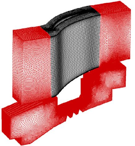
L. Cambier et al.: Mechanics & Industry 14, 159–174 (2013)                                                                  167

                            (a) Second order Jameson scheme
                                                                                                   Fig. 15. Isothermal round jet LES elsA simulation: vorticity
                                                                                                   and dilatation fields (courtesy of Cerfacs).

                               (b) Third order RBCi scheme

         Fig. 14. Unsteady flow simulation in the VKI BRITE HP
         turbine stage (elsA result from [28]).                                                    Fig. 16. Isothermal round jet simulation: spatial distribution
                                                                                                   of OASPL (courtesy of Cerfacs).

         the vortex ring perturbation applied to the inlet bound-
         ary. The dilatation field (Fig. 15) perpendicular to the jet                               matrix” for static coupling, modal approach, or full finite
         axis is a good indicator of the acoustic wave propagation.                                element structural model).
             The analysis of the overall sound pressure level
         (OASPL), which describes the contribution of all mea-
                                                                                                   5.4.1 Investigation of compressor blade vibrations due
         sured frequencies, shows that the noise directivity is ac-
                                                                                                         to subharmonic aerodynamic excitations
         curately captured and the maximum error compared to
                                                                                                         (Cenaero work)
         experimental data is around 2 dB (Fig. 16).
                                                                                                       The first example of an aeroelastic simulation (see
                                                                                                   Ref. [27] for more details) deals with the forced response
         5.4 Aeroelasticity                                                                        behaviour of a compressor blisk (resulting from the man-
                                                                                                   ufacturing of blades and disks as a single element). The
             The “Ael” subsystem of elsA [16,17] developed by the                                  one piece structure and the low weight of the blisk may
         Aeroelasticity and Structural Dynamics (DADS) Depart-                                     lead to poor vibrational performance that is worth being
         ment of Onera gives access in a unified formulation to var-                                known. The aeroelastic analysis is performed by comput-
         ious types of aeroelastic simulations. The simulation types                               ing the modal properties of the structure as well as the
         range from non-linear and linearized harmonic forced mo-                                  aerodynamical damping and forces acting on it.
         tion computations, to static coupling and consistent dy-                                      The forced response behaviour due to a subharmonic
         namic coupling simulations in the time-domain, with dif-                                  Blade Passing Frequency Excitation is studied on a blisk
         ferent levels of structural modelling (“reduced flexibility                                of a low pressure compressor, designed at Techspace Aero.

Downloaded from https://www.cambridge.org/core. IP address: 46.4.80.155, on 30 Sep 2021 at 04:23:41, subject to the Cambridge Core terms of use, available at https://www.cambridge.org/core/terms
. https://doi.org/10.1051/meca/2013056
168 L. Cambier et al.: Mechanics & Industry 14, 159–174 (2013)
Fig. 17. Configuration to provide the 10 N excitation: one
blade out of 10 stator blades is different (in red) (courtesy of
Cenaero).
Fig. 18. GAF signal in frequency domain (courtesy of
Cenaero).
The related Campbell and ZZENF diagrams show cross-
ing of the first bending mode with 10 engine orders
(1 F/10 N). Since there are 100 stator blades upstream of
the rotor, a practical solution to generate a subharmonic
excitation (10 N) is to replace one out of 10 blades by a
thicker one as presented in Figure 17.
The forced response is calculated in the following
steps. First, with the assumption of the cyclic symme-
try of the structure, only one sector is taken into account
for the Finite Element modal analysis resulting from cal-
culations with the Samcef code. Then, the aerodynamic
damping is estimated by the unsteady RANS simulations
performed with the elsA solver on a single rotor passage.
The Smith (k, l) turbulence model is used. The time ad-
vancing is simulated by the DTS technique. Finally, the
excitation force of 10 N is predicted by the elsA unsteady
RANS computations with the chorochronic approach for
the stage configuration shown in Figure 17.
Fig. 19. Amplification factor vs. frequency for mode 1 F and
One of the input parameters for the forced response excitation of 10 N (courtesy of Cenaero).
estimation is the aerodynamic damping which is related
to the flow unsteadiness generated by the blade dynamic
motion. To measure the aerodynamic damping, the forced 5.4.2 Dynamic forced response of a soft blade propeller due
harmonic motion corresponding to the mode 1 F with con- to incidence effect (Onera work)
stant amplitude is applied to the blade. This blade motion
generates unsteady pressure which can either excite the
structure or damp it. The analysis shows that the aerody- The DADS Department of Onera is in charge of de-
namic damping values for this test case are positive which veloping prediction capabilities concerning the aeroelastic
help to avoid the flutter instabilities. behaviour of soft blade propellers and CRORs, in terms of
flutter, whirl flutter and dynamic response, and also for
To evaluate the response of the mode 1 F, the ex- evaluation of global loads [17]. Hereafter are presented
citation corresponding to the 10 N should be extracted. some elsA results concerning the evaluation of the dy-
For this purpose, the calculated Generalized Aerodynamic namic response of a soft blade model of the front pro-
Forces (GAF) are transferred to the frequency domain us- peller of a generic CROR configuration, due to an inci-
ing Fast Fourier Transform. Figure 18 presents amplitude dence effect.
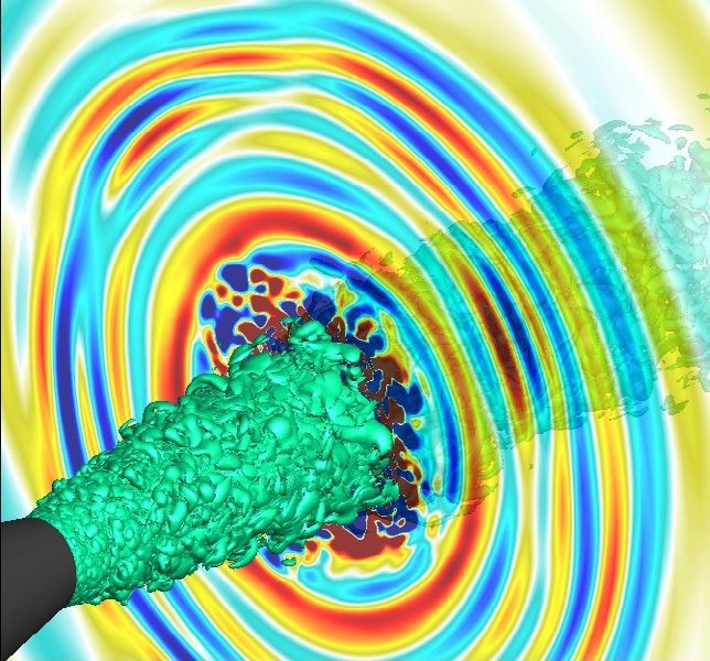
of the GAF versus the frequency. The part of the GAF The full 360◦ 11 blade generic propeller configuration
which shows the impact of the thicker blade (10 N) and (Fig. 20) is meshed, leading to a 121 structured block
the part of all stator blades (100 N) is shown in the figure. grid, including about 14 million cells. A view of the static
By taking into account only the excitation correspond- pressure field computed by elsA on the rigid propeller at
ing to the 10 N and solving the equation of motion of cruise conditions (M∞ = 0.73 and α∞ = 1◦ ) is shown. In
the structure, the forced response is estimated. Figure 19 this case, due to incidence, the flowfield is unsteady, and
presents the calculated amplification factor for a 10 N ex- produces a 1/rev periodic loading on each blade which is
citation. The comparison with the measurements reveals likely to induce periodic forced response of soft bladings,
that the computations underestimate the forced response. as shown below.
Downloaded from https://www.cambridge.org/core. IP address: 46.4.80.155, on 30 Sep 2021 at 04:23:41, subject to the Cambridge Core terms of use, available at https://www.cambridge.org/core/terms
. https://doi.org/10.1051/meca/2013056L. Cambier et al.: Mechanics & Industry 14, 159–174 (2013) 169
Fig. 21. Second bending response in time and frequency do-
mains at 1◦ angle of attack (Onera simulation).
Investigations continue on this configuration, espe-
cially concerning the development of whirl flutter predic-
tion capabilities for propellers as well as CROR models.
6 Concluding remarks
The wide range of applications both from industry
users and from Onera and research labs shows that the
elsA software has reached a high level of maturity, even
if we were not able to show all the covered fields, such as
CFD and wind tunnel synergy [36], car turbochargers [26],
steam turbines [31], wind turbines, missiles, launchers. . .
Further improvements are still requested for satisfying
Fig. 20. Unsteady elsA simulation on a generic propeller rigid the demand for better physical modelling (for the simu-
configuration (Onera simulation). lation of detached flows), for more accuracy (for exam-
ple, for aeroacoustics), for more efficiency (to deal with
the very fine meshes requested for simulating detached
In a second step, after rigid blade computations, flows), for faster response times (for even more intensive
aeroelastic dynamic fluid-structure coupled computations use in design loops or optimization loops). The feedback
have been carried out using the Ael aeroelasticity mod- of industry users on real-world configurations and the
ule of elsA, in order to study the forced response of the help of research partners to carry out the future enhance-
soft model, due to an incidence effect. A modal structural ments are more than ever necessary to cope with all these
model has been implemented, including first and second challenges.
bending and first torsion modes at nodal diameter 1, likely
to be excited by the diameter 1 loading due to incidence. Acknowledgements. We want to acknowledge the following
During the transient computation, several pieces of contributions to the paper: Snecma (Safran group) for Sec-
information are collected: generalized coordinates and tion 4.1, Airbus for Section 4.2, C. François (Onera) for the
forces histories, global loads history such as thrust or ver- landing aircraft simulation, Eurocopter for Section 4.3, G. Ngo
tical force. These data are post-processed in order to ex- Boum (LMFA) for the EARSM turbine simulation, V. Brunet
tract the frequency response in terms of blade deforma- (Onera) for the ZDES jet simulation, M. de la Llave Plata and
tion and forces: 1/rev forced response deformation and M.-C. Le Pape (Onera) for the simulations in hybrid grids, T.
force levels are extracted, as well as aeroelastic modal Renaud (Onera) for the Cartesian/curvilinear rotor simula-
tion, B. Michel (Onera) and P. Cinnella (Dynfluid) for RBC
dampings. Such an analysis, performed at the same cruise
results, H. Deniau (Cerfacs) for the high order LES jet noise
conditions, is presented in Figure 21. The 1/rev forced re-
simulation, F. Thirifay (Cenaero) for the blisk forced response
sponse peak is visible, as well as broader peaks at modal and A. Dugeai (Onera) for the propeller forced response. Many
frequencies, illustrating damped modes. thanks also to all those who have made elsA software project
Fluid-structure dynamic coupling simulations are con- so successful for many years! This paper is a revised version of
ducted with elsA/Ael over 10 full propeller rotation cy- a paper entitled “The Onera elsA CFD software: input from
cles, using the Spalart-Allmaras turbulence model. The research and feedback from industry” presented at the 28th In-
DTS scheme is used. Simulations are run in parallel on a ternational Congress of the Aeronautical Sciences, Brisbane,
Linux Xeon cluster using 44 processors, for about 5 days. 23rd–28th September 2012.
Downloaded from https://www.cambridge.org/core. IP address: 46.4.80.155, on 30 Sep 2021 at 04:23:41, subject to the Cambridge Core terms of use, available at https://www.cambridge.org/core/terms
. https://doi.org/10.1051/meca/2013056170 L. Cambier et al.: Mechanics & Industry 14, 159–174 (2013)
Appendix N. Bulot, I. Trébinjac, X. Ottavy, P. Kulisa, G. Halter,
B. Paoletti, P. Krikorian, Experimental and numerical
Over the years, elsA has been the basis for many stud- investigation of the flow field in a high-pressure cen-
ies by Onera and research partners which have been pub- trifugal compressor impeller surge, J. Power Energy
lished in international journals. In addition to the 17 ref- 223 (2009) 657–666
erences [4–7,11,12,16,18–25,28,29] based on elsA in peer- L. Castillon, G. Legras, Overset grid method for sim-
reviewed journals, the following list (alphabetically by the ulation of compressors with nonaxisymmetric casing
first author) gathers nearly 100 other papers dealing with treatment, J. Propuls. Power 29 (2013)
elsA in such journals. This list is again a demonstration J. Cliquet, R. Houdeville, D. Arnal, Application of lami-
of cooperative work about elsA since the co-authors of- nar turbulent criteria in Navier-Stokes computations,
ten belong to several research labs, or to both research AIAA J. 46 (2008) 1182–1190
laboratories and industry.
Y. Colin, H. Deniau, J.-F. Boussuge, A robust low speed
G. Alleon, S. Champagneux, G. Chevalier, L. Giraud, preconditioning formulation for viscous flow computa-
G. Sylvand, Parallel distributed numerical simulations tions, Comput. Fluids 47 (2011) 1–15
in aeronautic applications, J. Appl. Math. Model. 30 E. Collado, N. Gourdain, F. Duchaine, L.Y.M. Gicquel,
(2006) 714–730 Effects of free-stream turbulence on high pressure tur-
P. Ardonceau, S. Trapier, Drag evolution of a rectangu- bine blade heat transfer predicted by structured and
lar wing with triggered wing-tip separation, J. Aircraft unstructured LES, J. Heat Mass Transfer 55 (2012)
42 (2005) 1369–1371 5754−5768
C. Benoit, G. Jeanfaivre, Three-dimensional inviscid iso- B. Courbet, C. Benoit, V. Couaillier, F. Haider, M.-C.
lated rotor calculations using chimera and automatic Le Pape, S. Péron, Space Discretization methods,
cartesian partitioning methods, J. Am. Helicopter Soc. Aerospace Lab 2 (2011)
48 (2003) 128–138 N. Courtiade, X. Ottavy, N. Gourdain, Modal decom-
A. Benyahia, R. Houdeville, Transition prediction in position for the analysis of the rotor-stator interac-
transonic turbine configurations using a correlation- tions in multistage compressors, J. Thermal Science
based transport equation model, Int. J. Eng. Syst. 21 (2012) 276–285
Model. Simul. 3 (2011) 36–45 D. Destarac, J. van der Vooren, Drag/thrust analysis
F. Blanc, Patch assembly: An automated overlapping of jet-propelled transonic transport aircraft; definition
grid assembly strategy, J. Aircraft 47 (2010) 110–119 of physical drag components, Aerosp. Sci. Technol. 8
F. Blanc, F.X. Roux, J.-C. Jouhaud, Harmonic balance- (2004) 545–556
based code-coupling strategy for the calculation of G. Dufour, F. Sicot, G. Puigt, C. Liauzun, A. Dugeai,
aeroelastic system response to forced excitation, Contrasting the harmonic balance and linearized
AIAA J. 48 (2010) 2472–2481 methods for oscillating-flap simulations, AIAA J. 48
S. Bocquet, P. Sagaut, J.-C. Jouhaud, A compressible (2010) 788–797
wall model for Large-Eddy Simulation with applica- A. Dumont, A. Le Pape, J. Peter, S. Huberson, Aero-
tion to prediction of aerothermal quantities, Phys. dynamic shape optimization of hovering rotors using
Fluids 24 (2012) a discrete adjoint of the Reynolds-Averaged Navier-
T. Braconnier, M. Ferrier, J.-C. Jouhaud, M. Stokes equations, J. Am. Helicopter Soc. 56 (2011)
Montagnac, P. Sagaut, Towards an adaptive 032002
POD/SVD surrogate model for aerodynamic de- F. Gand, V. Brunet, S. Deck, Experimental and numer-
sign, Comput. Fluids 40 (2011) 195–209 ical investigation of a wing-body junction flow, AIAA
O. Brodersen, M. Rakowitz, S. Amant, P. Larrieu, D. J. 50 (2012) 2711–2719
Destarac, M. Sutcliffe, Airbus, ONERA, and DLR re- F. Gand, Zonal Detached Eddy Simulation of a civil
sults from the second AIAA Drag Prediction Work- aircraft with a deflected spoiler, AIAA J. 51 (2013)
shop, J. Aircraft 42 (2005) 932–940 697−706
N. Buffaz, I. Trébinjac, Detailed analysis of the flow in E. Garnier, P.Y. Pamart, J. Dandois, P. Sagaut, Evalu-
the inducer of a transonic centrifugal compressor, J. ation of the unsteady RANS capabilities for separated
Thermal Science 21 (2012) 1–12 flows control, Comput. Fluids, 61 (2012) 39–45
N. Bulot, I. Trébinjac, Impeller-diffuser interaction: A. Giauque, B. Ortun, B. Rodriguez, B. Caruelle, Nu-
analysis of the unsteady flow structures based on their merical error analysis with application to transonic
direction of propagation, J. Thermal Science 16 (2007) propeller aeroacoustics, Comput. Fluids, 69 (2012)
193–202 20−34
N. Bulot, I. Trébinjac, Effect of the unsteadiness L.Y.M. Gicquel, N. Gourdain, J.-F. Boussuge, H.
on the diffuser flow in a transonic compressor Deniau, G. Staffelbach, P. Wolf, T. Poinsot, High per-
stage, International Journal of Rotating Machinery formance parallel computing of flows in complex ge-
DOI:10.1155/2009/935293 (2009) ometries, C. R. Mécanique 339 (2011) 104–124
Downloaded from https://www.cambridge.org/core. IP address: 46.4.80.155, on 30 Sep 2021 at 04:23:41, subject to the Cambridge Core terms of use, available at https://www.cambridge.org/core/terms
. https://doi.org/10.1051/meca/2013056L. Cambier et al.: Mechanics & Industry 14, 159–174 (2013) 171
N. Gourdain, L.Y.M. Gicquel, G. Staffelbach, O. B. Landmann, M. Montagnac, A highly automated par-
Vermorel, F. Duchaine, J.-F. Boussuge, T. Poinsot, allel Chimera method for overset grids based on the
High performance parallel computing of flows in com- implicit hole cutting technique, Int. J. Numer. Meth-
plex geometries – part 2: applications, Comput. Sci. ods Fluids, 66 (2011) 778–804
Discovery 2 (2009) 1–28 J. Laurenceau, P. Sagaut, Building efficient response sur-
N. Gourdain, F. Leboeuf, Unsteady simulation of an ax- faces of aerodynamic functions with kriging and cok-
ial compressor stage with casing and blade passive riging, AIAA J. 46 (2008) 498–507
treatments, J. Turbomach. 131 (2009) 021013 J. Laurenceau, M. Meaux, M. Montagnac, P. Sagaut,
N. Gourdain, M. Montagnac, J.-F. Boussuge, Numerical Comparison of gradient-based and gradient-enhanced
Simulation of an axial compressor with non axisymet- response-surface-based optimizers, AIAA J. 48 (2010)
ric casing treatment, Progress in Propulsion Physics 1 981–994
(2009) 593–608 C. Laurent, I. Mary, V. Gleize, A. Lerat, D. Arnal, DNS
N. Gourdain, S. Burguburu, F. Leboeuf, G. Michon, database of a transitional separation bubble on a flat
Simulation of rotating stall in a whole stage of an axial plate and application to RANS modeling validation,
compressor, Comput. Fluids 39 (2010) 1644–1655 Comput. Fluids 61 (2012) 21–30
N. Gourdain, M. Montagnac, F. Wlassow, M. Gazaix, S. Lavagnoli, T. Yasa, G. Paniagua, L. Castillon, S.
High performance computing to simulate large scale Duni, Aerodynamic analysis of an innovative low pres-
industrial flows in multistage compressors, Int. J. High sure vane placed in an s-shape duct, J. Turbomach.
Perform. Comput. Appl. 24 (2010) 429–443 134 (2012)
N. Gourdain, L.Y.M. Gicquel, E. Collado, Comparison G. Legras, N. Gourdain, I. Trebinjac, Numerical anal-
of RANS simulation and LES for prediction of wall ysis of the tip leakage flow field in a transonic axial
heat transfer in a highly loaded turbine guide vane, J. compressor with circumferential casing treatment, J.
of Propuls. Power 28 (2012) 423–433 Thermal Science 19 (2010) 198–205
N. Gourdain, F. Wlassow, X. Ottavy, Effect of tip clear- G. Legras, I. Trebinjac, N. Gourdain, N Ottavy, L.
ance dimensions and control of unsteady flows in a Castillon, A novel approach to evaluate the benefits
multi-stage high-pressure compressor, J. Turbomach. of casing treatment in axial compressors, Int. J. Ro-
134 (2012) 051005 tating Machinery DOI:10.1155/2012/975407 (2012)
T. Guedeney, A. Gomar, F. Gallard, F. Sicot, G. Dufour, A. Le Pape, J. Lecanu, 3D Navier-Stokes computations
G. Puigt, Non-uniform time sampling for multiple- of a stall regulated wind turbine, Wind Energ. 7 (2004)
frequency harmonic balance computations, J. Com- 309–324
put. Phys. 236 (2013) 317–345 A. Le Pape, P. Beaumier, Numerical optimization of
helicopter rotor aerodynamic performance in hover,
J.-L. Hantrais-Gervois, A. Cartiéri, S. Mouton, J.-F.
Aerosp. Sci. Technol. 9 (2005) 191–201
Piat, Empty wind tunnel flow field computations, Int.
J. Eng. Syst. Model. Simul. 2 (2010) 46–57 I. Lepot, M. Leborgne, R. Schnell, J. Yin, G. Delattre,
F. Falissard, J. Talbotec, Aero-mechanical optimiza-
D. Hue, S. Esquieu, Computational Drag Prediction of tion of a contra-rotating open rotor and assessment of
the DPW4 configuration using the far-field approach, its aerodynamic and acoustic characteristics, J. Power
J. Aircraft 48 (2011) 1658–1670 Energ. 225 (2011) 850–863
E. Iuliano, D. Quagliarella, R.S. Donelli, I. Salah El Din, L.S. Lorente, J.M. Vega, A. Velazquez, Efficient com-
D. Arnal, Design of a supersonic natural laminar flow putation of the POD manifold containing the infor-
wing-body, J. Aircraft 48 (2011) 1147–1162 mation required to generate a multi-parameter aero-
G. Joubert, A. Le Pape, B. Heine, S. Huberson, Vor- dynamic database, Aerosp. Sci. Technol. 25 (2013)
tical interactions behind deployable vortex genera- 152−160
tor for airfoil static stall control, AIAA J. 51 (2013) C. Marmignon, V. Couaillier, B. Courbet, Solution
240–252 strategies for integration of semi-discretized flox equa-
J.-C. Jouhaud, M. Montagnac, L. Tourrette, A multi- tions in elsA and CEDRE, Aerospace Lab 2 (2011)
grid adaptive mesh refinement strategy for 3D aerody- A. Marsan, I. Trébinjac, S. Coste, G. Leroy, Study and
namic design, Int. J. Numer. Methods Fluids 47 (2005) control of a radial vaned diffuser stall, Int. J. Rotating
367–385 Machinery DOI:10.1155/2012/549048 (2012)
J.-C. Jouhaud, P. Sagaut, B. Labeyrie, A kriging ap- J. Marty, B. Aupoix, Interaction of shrouded stator flow
proach for CFD/Wind tunnel data comparison, J. and main flow and its influence on performances of a
Fluid Eng. 128 (2006) 847–855 three-stage high pressure compressor, J. Power Energy
J.-C. Jouhaud, P. Sagaut, M. Montagnac, J. Laurenceau, 226 (2012) 489–500
A surrogate-model based multi-disciplinary shape op- Y. Mauffrey, G. Rahier, J. Prieur, Numerical investi-
timization method with application to a 2d subsonic gation on blade/wake interaction noise generation, J.
airfoil, Comput. Fluids 36 (2007) 520–529 Aircraft 46 (2009) 1479–1486
Downloaded from https://www.cambridge.org/core. IP address: 46.4.80.155, on 30 Sep 2021 at 04:23:41, subject to the Cambridge Core terms of use, available at https://www.cambridge.org/core/terms
. https://doi.org/10.1051/meca/2013056172 L. Cambier et al.: Mechanics & Industry 14, 159–174 (2013)
M. Méheut, D. Bailly, Drag-Breakdown methods from A. Placzek, D.M. Tran, R. Ohayon, A nonlinear POD-
wake measurements, AIAA J. 46 (2008) 847–862 Galerkin reduced-order model for compressible flows
M. Meunier, V. Brunet, High-lift devices performance taking into account rigid body motions, Comput.
enhancement using mechanical and air-jet vortex gen- Methods Appl. Mech. Eng. 200 (2011) 3497–3514
erators, J. Aircraft 45 (2008) 2049–2061 C. Polacsek, S. Burguburu, S. Redonnet, M. Terracol,
M. Meunier, Simulation and optimization of flow control Numerical simulations of fan interaction noise using a
strategies for novel high-lift configurations, AIAA J. hybrid approach, AIAA J. 44 (2006) 1188–1196
47 (2009) 1145–1157 G. Reboul, C. Polacsek, Towards numerical simulation of
B. Mialon et al., Validation of numerical prediction fan broadband noise aft radiation from aero-engines,
of dynamic derivatives, Prog. Aerosp. Sci. 47 (2011) AIAA J. 28 (2010) 2038–2048
674−694 S. Redonnet, Y. Druon, Computational aeroacoustics of
F. Moens, J. Perraud, A. Séraudie, R. Houdeville, Tran- aft fan noises characterizing a realistic co-axial engine,
sition measurement and prediction on a generic high- AIAA J. 50 (2012) 1029–1046
lift swept wing, J. Aerosp. Eng. 220 (2006) 589–603 F. Renac, Improvement of the recursive projection
F. Moens, J. Perraud, A. Krumbein, T. Toulorge, P. Ian- method for linear iterative scheme stabilization based
on an approximate eigenvalue problem, J. Comput.
nelli, P. Eliasson, A. Hanifi, Transition prediction and
Phys. 230 (2011) 5739–5752
impact on a three-dimensional high-lift-wing configu-
ration, J. Aircraft 45 (2008) 1751–1766 J. Reneaux, V. Brunet, S. Esquieu, M. Meunier, S. Mou-
ton, Recent achievements in numerical simulation for
B. Ortun, R. Boisard, I. Gonzalez-Martino, Assessment
aircraft power-plant configurations, The Aeronautical
of propeller 1P loads predictions, Int. J. Eng. Syst.
Journal 117 (2013) 1–17
Model. Simul. 4 (2012) 36–46
K. Richter, A. Le Pape, T. Knopp, M. Costes, V. Gleize,
X. Ottavy, N. Courtiade, N. Gourdain, Experimental
A.D. Gardner, Improved two-dimensional dynamic
and computational methods for flow investigation in
stall prediction with structured and hybrid numerical
high-speed multistage compressor, J. Propuls. Power
methods, J. Amer. Helicopter Soc. 56 (2011) 1–12
28 (2012) 1141–1155
N. Rochuon, I. Trébinjac, G. Billonnet, An extraction
G. Paniagua, T. Yasa, A. de la Loma, L. Castillon, T. of the dominant rotor-stator interaction modes by the
Coton, Unsteady strong shocks interactions in a tran- use of Proper Orthogonal Decomposition (POD), J.
sonic turbine : experimental and numerical analysis, Thermal Sciences 15 (2006) 109–114
J. Propuls. Power 24 (2008)
N. Rochuon, I. Trébinjac, P. Kulisa, G. Billonnet,
M. Pau, G. Paniagua, D. Delhaye, A. de la Loma, P. Assessment of jet-wake flow structures induced by
Ginibre, Aerothermal impact of stator-rim purge flow three-dimensional hub wall contouring, Int. Rev.
and rotor-platform film cooling on a transonic turbine Mech. Eng. 2 (2008) 113–121
stage, J. Turbomach. 132 (2010) 021006
A. Sachdeva, F. Leboeuf, Topological studies of Three-
J. Perraud, F. Moens, A. Séraudie, Transition on a high Dimensional Flows in a High Pressure Compressor
lift swept wing in the European project EUROLIFT, Stator Blade Row without and with Boundary Layer
J. Aircraft 41 (2004) 1183–1190 Aspiration, Chinese Journal of Aeronautics 24 (2011)
J. Perraud, J. Cliquet, R. Houdeville, D. Arnal, F. 541–549
Moens, Transport aircraft three-dimensional high-lift- X. de Saint Victor, Estimation of the accuracy of numer-
wing numerical transition prediction, J. Aircraft 45 ical simulations using Richardson extrapolation and a
(2008) 1554–1563 Hessian technique, Int. J. Eng. Syst. Model. Simul. 2
J. Peter, F. Drullion, Large stencil viscous flux lineariza- (2010) 25–37
tion for the simulation of 3D compressible turbulent X. de Saint Victor, Numerical simulations of unsteady
flows with backward-Euler schemes, Comput. Fluids separation bubbles over turbine blades, Int. J. Fluid
36 (2007) 1005–1027 Mech. Res. 39 (2012) 40–53
J. Peter, M. Marcelet, Comparison of surrogate models S. Salvadori, F. Montomoli, F. Martelli, P. Adami, K.S.
for turbomachinery design, WSEAS Transactions on Chana, L. Castillon, Aerothermal study of the un-
Fluid Mechanics 1 (2007) 10–17 steady flow field in a transonic gas turbine with inlet
J. Peter, M. Lazareff, V. Couaillier, Verification, vali- temperature distortions, J. Turbomach. 133-031030
dation and error estimation in CFD for compressible (2011) 1–13
flows, Int. J. Eng. Syst. Model. Simul. 2 (2010) 75–87 A. Séraudie, J. Perraud, F. Moens, Transition measure-
J. Peter, M. Nguyen-Dinh, P. Trontin, Goal oriented ment and analysis on a swept wing in high lift config-
mesh adaptation using total derivative of aerodynamic uration, Aerosp. Sci. Technol. 7 (2003) 569–576
functions with respect to mesh coordinates – With ap- F. Sicot, G. Puigt, M. Montagnac, Block-Jacobi implicit
plications to Euler flows, Comput. Fluids 66 (2012) algorithms for the time spectral method, AIAA J. 46
194–214 (2008) 3080–3089
Downloaded from https://www.cambridge.org/core. IP address: 46.4.80.155, on 30 Sep 2021 at 04:23:41, subject to the Cambridge Core terms of use, available at https://www.cambridge.org/core/terms
. https://doi.org/10.1051/meca/2013056You can also read