Three-dimensional laser welding
←
→
Page content transcription
If your browser does not render page correctly, please read the page content below
Three-dimensional laser welding

Jerry Zybko, LEISTER Technologies, LLC, Itasca, IL, USA
J.W. Chen, LEISTER Process Technologies, Sarnen/Switzerland

Utilizing laser as a method to join plastic components is growing in popularity. The
ability to create clean, strong and consistent hermetic seals is very attractive for
manufacturers.     One necessary process requirement, that being clamping the
componets to create good physical contact between the parts, created challenges for
assemblies that were beyond simple two-dimensional contours.

A new laser-joining method has been designed to assist in welding three-dimensional
comoponents or large two dimensional assemblies. The core concept is to utilize the
optic element to both precisely delivery the laser energy and to apply the necessary
contact force, thus eliminating the need for a verticle, mechanical clamping device. To
accomplish this, a glass ball on a frictionless air-bearing is put into position and pressure
is applied via a self contained pneumatic slide.

1. Introduction

Lasers have become an indispensable method for metal processing and have been
very popular in plastics, mainly in the areas of marking, cutting and drilling [1]. Plastic
assembly has long been dominated by ultrasonic welding [2], vibration welding [3] and
hot plate welding [4]. Over the last decade laser welding has gained popularity as a
complementary joining process for plastics and has been successfully introduced in
many industrial application areas [5].

Laser transmission welding offers an attractive alternative where conventional plastic
joining technologies reach their limits. The most common concepts currently pursued are
contour welding, simultaneous welding, quasi-simultaneous welding and the patented
mask welding method [6,7]. Despite all these new process developments, the laser
welding technique and other conventional joining processes have not managed to
overcome the ultimate technical barrier, three-dimensional welding. Vibration, ultrasonic
and laser transmission techniques, with all their established process concepts, have
been limited to welding components with two-dimensional seam geometries or
applications with slight curvature or contour. There remain many industrial applications
that require exterior tube sealing or elaborate three-dimensional weld areas.

2. Laser transmission welding and its technical limitations

With respect to the nature of beam delivery, there is little difference between the
techniques used for metal and plastic welding. The essential difference in the plastic
welding approach is the through transmission IR concept.

                    Figure 1: The laser transmission welding principle

The necessity for physical contact in the plastic welding process arises from the basic
principle of laser transmission welding as shown in Figure 1. Once the parts to be joined
have been brought into contact, the laser beam penetrates through the top transparent
layer/component. The beam energy is transformed into heat by the absorbent joining
part, plasticizing the material at this point. The transparent part is melted by thermal
conduction as a result of the physical contact with the absorbing layer. An impermeable
weld is produced between the two joining partners in the weld area.

External contact pressure is applied to achieve an uninterrupted contact between the
plastic components in the weld area. Good welding quality therefore depends on the
regulation of laser energy, the interaction between the laser beam and the plastic
material, and good physical contact. The standard method used to create a physical
contact between the two components is to incorporate a clamping system, typically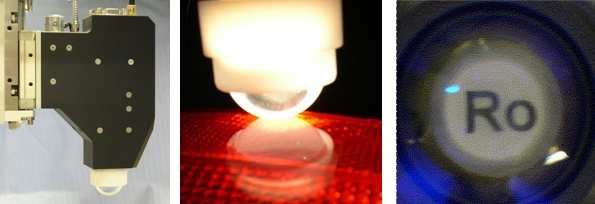
utilizing pneumatic cylinders to push the parts up against a metal frame or glass plate.
Good clamping conditions can easily be achieved for smaller two-dimensional weld
contours however, larger two-dimensional and three-dimensional welding contours make
it difficult to maintain static contact between the joining areas along the entire welding
contour.
3. Welding concept for three-dimensional joining applications
A new concept was recently introduced [8] to eliminate the technical limitations
encountered in the use of clamping systems and to facilitate the use of laser for three-
dimensional joining. With this new process the contact pressure required for the joining
process is constantly regulated to act dynamically, selectively, perpendicularly and
precisely at the desired joining area.
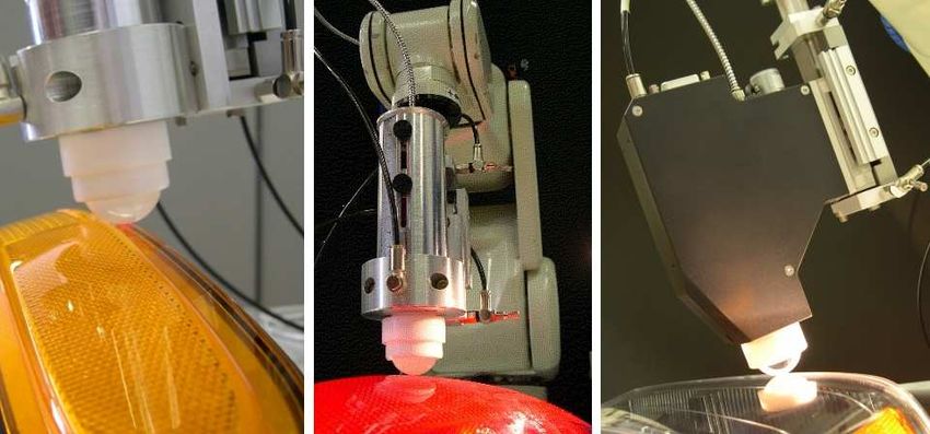
The welding concept essentially works on the contour welding principle, whereby the
laser spot follows a contour and the component is sequentially welded. A laser spot is
focused on the joining plane by means of an air bearing, frictionless, rotating glass
sphere as shown in Figure 2.
Figure 2: Schematic diagram of the welding technique
The glass sphere lens serves as a mechanical pressing tool applied perpendicularly at
each point on the joining plane. This ensures that the laser beam is only incident at the
site where the contact pressure is applied. This process concept offers the possibility of
applying the necessary contact pressure concurrent with the laser beam being
continuously moved along a welding contour. The air bearing glass sphere lens is fitted
in a robust and compact processing head together with the optical fiber connector and
other optical systems and process monitoring sensors.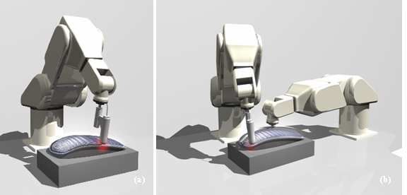
As with a standard diode laser the light is emitted in a conical shape. The focal distance
between the two internal lenses can be adjusted to create the desired weld width
regardless of the thicknesses of the top component. The contour motion of this
processing head is typically controlled with the aid of a 6-axis robot (see Figure 3a). A
pneumatic cylinder is integrated into the laser head to accurately and consistently control
the force applied between the glass ball and the component. A second air supply is
applied internally behind the glass ball and the pressure is equalized.
Figure 3: (a) The contour motion with a 6-axis robotic system. (b) The 2-step
manufacturing process for a rigid component using a robotic assembly system.
Since the relative motion between the processing head and workpiece is always subject
to mechanical contact, the air bearing of the glass sphere lens not only serves to protect
the glass surface against mechanical damage, but the moving glass sphere effectively
avoids the risk of lateral shift of the component. If the components cannot be sufficiently
nested into a fixture that would maintain precise alignment a robot can be utilized to
maintain relative positioning during the weld process (see Figure 3b). Other techniques,
such as snap-fits or automated timed clamping elements, can be used to maintain
positioning and eliminate a spot welding step.
This new welding concept is also used for welding large, flat assemblies or flexible
sheets/fabrics utilizing, for example, and XY gantry system. Continuous roll-to-roll
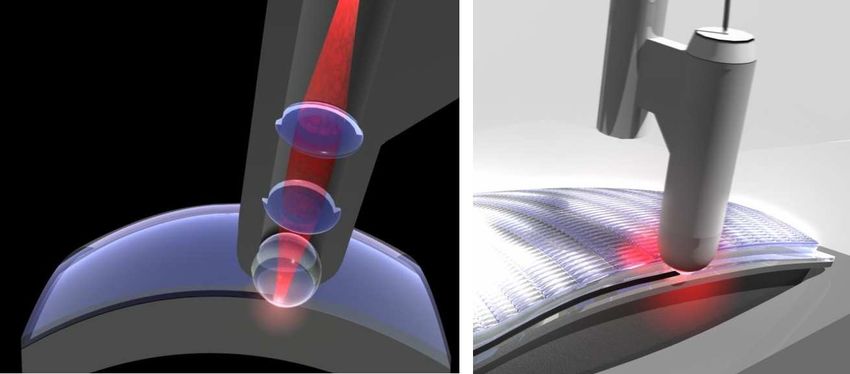
applications are also possible.4. Process implementation and process monitoring The positioning of the processing head perpendicular to the joining plane is a core functional requirement, Good welding quality can only be achieved if the welding process takes place entirely under contact pressure. Figure 4: (a) Process head mounted on pneumatic slide. (b) Frictionless rolling glass sphere lens pressed on the assembly. (c) Camera image through the glass sphere lens with the optical object on the welding plane. The laser head is mounted on a pneumatic slide. This design allows for easier robot programing, using the stroke of the slide to act as a buffer and compansating for slight part deviations. (see Figure 4a). The new process offers all the established options for process monitoring. The surface temperature on the joining plane can be monitored using an infrared sensor integrated in the processing head. Laser power is regulated online on the basis of the measured IR to create a constant joining temperature. Some robots can receive a feedback signal that allows for synchronized laser power adjustment. This is important when welding assemblies that have weld patterns that have a combination of high-speed straight portions (requiring high laser power) and sharp or tight corners where the robot to slow down (requiring lower laser power). Adjusting the laser power allows for a consistent weld pattern regardless of speed. Lastly, the joining process can be visualized online directly beneath the glass sphere by means of a camera integrated in the optical system (Figure 4c). The information can also be used to assess the welding seam quality. 6. Conclusion
Laser welding is emerging as an important welding technique in plastics processing. The
diverse fields of application always call for new techniques and innovative problem
solving approaches. Though various laser transmission welding techniques have been
introduced that complement conventional joining methods, the innovative potential of
laser transmission welding has yet to be fully exploited.

By virtue of its precise and controllable application of the necessary joining force this
process produces an optically perfect welding seam, which is of crucial importance in the
manufacture of decorative components. A typical example is the manufacture of
automobile headlights or tail lights, which require a three-dimensional welding seam.

       Figure 6: Application example – Welding of automobile tail lights. Patented

Another trend is the use of highly transparent plastic materials. The welding seams
remain visible as decoration. The decorative effect has thus become a decisive criterion
for such products.

The method presented in this paper integrates the clamping mechanism into the laser
head, making it possible to extend conventional laser plastic welding from small to
medium sized two-dimensional applications to three-dimensional are large two
dimensional assemblies. This technical advancement eliminates the constraints
associated with standard clamping methods and allows for enhanced welding quality via
a localized application of contact force.
8. References
[1] Korte, J.: Laserschweißen von Thermoplasten, Dissertation an der Universität – GH
Paderborn (1998)
[2] Haberstroh, E.: Untersuchung prozessübergreifender Qualitätssicherungskonzepte beim
Ultraschallschweißen unter Anwendung statischer Methoden; Abschlussbericht zum
AiF-Forschungsvorhaben 11.372 N; Aachen (2000)
[3] Watson, M. N.: Welding Plastics: A Primer; Automotive Engineering, Heft 94 (1986) 12,
S.55-61
[4] Pecha, E.: Trennung auf längere Sicht ausgeschlossen, Plastverarbeiter 35 (1984) 3,
S.106-109
[5] Pütz, H., Hänsch, D., Treusch, H.G. und Pflueger, S.: Laser welding offers array of
assembly advantages, In Modern Plastics, S.121-124 (1997)
[6] Chen, J.-W.: Laserfügeverfahren und Vorrichtungen zum Verbinden von verschiedenen
Werkstücken aus Kunststoff oder Kunststoff mit anderen Materialien, Europäisches
Patent, EP 0 997 261,1 Anmeldetag: 28.01.1999
(7] Chen, J.-W. und Zybko, J.: Laser assembly technology for planar microfluidic devices,
Annual Technical Conference, May 2002, San Francisco, CA
[8] Chen, J.-W.: ″Globo-Welding″ - Verfahren zum dreidimensionalen
Kunststoffschweissen, Wettbewerbsantrag für «Swiss Technology Award 2004»You can also read