TIMBERSLED ARO/RIOT INSTALL KIT - APPLICATION P/N 9928509
←
→
Page content transcription
If your browser does not render page correctly, please read the page content below
TIMBERSLED® ARO™ /RIOT™ INSTALL KIT

P/N 9928509
APPLICATION
                                        NOTICE
               All Timbersled RIOT chassis use the ARO installation kits.

Installation instructions are for all ARO TSS and ARO TFS installation kits required to
mount the Timbersled ARO/RIOT chassis to your specific vehicle. The Timbersled ARO
and RIOT kits are designed to fit a variety of makes and models of bikes. For specific
details on your bikes install kit visit Timbersled.com or scan the QR code if using a
mobile device. If viewing on a PC click HERE
BEFORE YOU BEGIN
Read these instructions and check to be sure all parts and tools are accounted for. Please retain these
installation instructions for future reference and parts ordering information.
KIT CONTENTS
The ARO chassis can be installed using either the ARO TSS (Timbersled Suspension Strut) Install Kit or the
ARO TFS (Timbersled Fixed Strut) Install Kit. Refer to the images below for a general overview of what is
included in the install kits. Your specific kit may vary slightly depending on make and model.

TSS Kit

                               Instr 9928509    Rev 02 2019-10      Page 1 of 16
REF       QTY   PART DESCRIPTION                                                    PART NUMBER
1         1     Spacer Pack                                                         -

2         1     Fork Clamp                                                          -

3         1     Strut Rod Reducer Pack                                              -
4         1     Strut Rod TSS                                                       -
5         1     TSS Shock Body                                                      -

          1     Instructions                                                        9928509

TFS Kit

REF       QTY   PART DESCRIPTION                                                    PART NUMBER
1         1     Spacer Pack                                                         -

2         1     Fork Clamp                                                          -

3         1     Strut Rod Reducer Pack                                              -
4         1     Strut - Solid, Adjustable                                           -

          1     Instructions                                                        9928509

TOOLS REQUIRED
• Safety Glasses                                        • Pliers, Slip Joint
• Hammer, Soft Face                                     • Screwdriver, Standard
• Hex Key Set, Metric                                   • Tin Snips, Straight Cut

                                Instr 9928509   Rev 02 2019-10    Page 2 of 16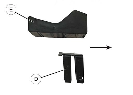
• Socket Set, Hex Bit, Metric                                 • Vehicle Lift/Support Equipment
• Socket Set, Metric                                          • Model Specific Timbersled ARO Fitment Table
• Wrench Set, Metric                                          • Torque Wrench

IMPORTANT
Your TIMBERSLED® ARO™/RIOT™ Install Kit is exclusively designed for your vehicle. Please read the
installation instructions thoroughly before beginning. Installation is easier if the vehicle is clean and free of
debris. For your safety, and to ensure a satisfactory installation, perform all installation steps correctly in the
sequence shown.
INSTALLATION INSTRUCTIONS
                                                              3. Remove the air filter, roost guard, chain, upper and
The instructions listed are universal for all bikes using        lower chain rollers and chain guides from bike
the Timbersled ARO/RIOT snowbike kit. The process                frame. These parts will not be needed while the
in the instructions may vary slightly between makes              Timbersled kit is installed on the bike.
and models. Refer to your host bike’s owner’s manual                                  NOTICE
for specific references and assembly/disassembly
procedures.                                                     Do not start or operate motorcycle while air filter is
                                                               removed. Timbersled recommends plugging your air
You will also need a copy of the Timbersled Fitment              intake with a clean lint-free towel while air filter is
Table for your specific bike model. The Timbersled               removed to prevent any debris from entering the
Fitment Table can be found and printed at Timbersled.                     motorcycle's air intake system.
com or by contacting your local Timbersled dealer.

MOTORCYCLE REAR DISASSEMBLY                                   4. Remove the foot-brake master cylinder and lever
                                                                 from the bike frame.
                                                              5. Remove the upper shock bolt from frame and
                                                                 retain for later installation.
                                                              6. Remove the suspension linkage bolt from the
                                                                 frame if your bike has one. This will not be used
                                                                 with the Timbersled kit.
                                                              7. Remove the swing arm pivot bolt. You will re-use
                                                                 this with your Timbersled kit installation later.
                                                              8. Remove the shock, tire, brake, and swing arm
                                                                 assembly from the bike as a complete assembly.
                                                                 These parts will not be needed while the
                                                                 Timbersled kit is installed on the bike.
                                                                                      NOTICE
1. Place bike on a stand or suitable support where             It is recommended to cable tie all bushings, spacers,
   both wheels are off the ground. Secure properly to          etc. to their corresponding parts at all pivoting points
   prevent bike from tipping when wheels are                          to prevent losing any parts during storage.
   removed.
                        NOTICE                                9. Remove the complete front brake system keeping
    An adjustable stand is helpful for reassembly.               the entire system intact. Their is no need to dis-
                                                                 connect the brake line from the master cylinder or
                                                                 brake caliper.
2. Remove the seat, side panels, frame guards, and
   exhaust silencer. Retain these parts for later re-            First remove the front caliper from the motorcycle's
   installation.                                                 lower front fork tube. Next remove the front brake
                                                                 lever and master cylinder from the motorcycle's
                                                                 handle bars and remove the entire front brake
                                                                 system as a single unit.

                                 Instr 9928509     Rev 02 2019-10       Page 3 of 16
FRAME BUSHING AND SUB-FRAME
REDUCER INSTALLATION
There are two different types of ARO/RIOT install kits
available. The TSS (Timbersled Suspension Strut)
install kit and the TFS (Timbersled Fixed Strut) install
kit. Installation procedures for the sub-frame bushings
and reducers are universal for either kit.
NOTICE
Your ARO/RIOT pivot forging sub-frame comes with
the pivot bushings pre-installed. If install kit spacer
packs come with extra sub-frame pivot bushings you
will not need them for the ARO/RIOT installation.
1. Install the sub-frame reducers into their proper NOTICE
location in the pivot forging. To locate the sub-frame reducer positioning for your
If reducer bushing is black in color, first place an specific bike, refer to the Timbersled Fitment
O-ring B on each of the sub-frame reducers A Tables. Fitment tables can be found and printed at
used. Put a coating of grease on the inside of the Timbersled.com or by contacting your local
bushing and the outside of the spacer/reducer and Timbersled Dealer. Each of the sub-frame spacers/
install them into the frame. They should slip in reducers will have a part number stamped on the
without interference. end that will be its reference number on the fitment
table to show their location.
If the bushings are white in color and do not have
a step in them for the O-ring, DO NOT install the
O-ring, Grease is not needed on the white/creme
bushings.
Instr 9928509 Rev 02 2019-10 Page 4 of 16REAR TRACK ASSEMBLY INSTALLATION 3. Next you will need to install either the TSS shock
strut or the fixed strut rod depending on which
1. Insert the rear track assembly into the bike
installation kit you have. The Timbersled install kits
between the engine and the frame. It may be a
come with all necessary reducers and spacers to
snug fit due to the O-rings holding the spacers out.
install the Timbersled chassis to your motorcycle.
It should squeeze in as you firmly push the
assembly into place. Visually make sure The Timbersled ARO/RIOT chassis only requires
everything looks correct and is aligned properly. installation of the upper strut rod reducers. Install
the upper strut rod reducers into the upper shock
body ball joint for the TSS kit or into the upper ball
joint of the strut rod for the TFS kit.
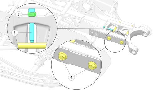
The lower rod ends on the ARO/RIOT strut rods
utilize a trunnion ball-joint that bolts directly to the
forged pivot frame using two M8 x 1.25" bolts A
included with your Timbersled ARO/RIOT unit.
These bolts will be located in a zip-loc bag with
your owner's manual and drive chain. Their is no
need for lower strut rod reducers.
NOTICE
TSS and TFS use different upper strut rod reducers
for the same bike.
NOTICE
It may be helpful to gently squeeze the reducers with
an adjustable pliers or clamp in the frame eyelets
prior to installation to ensure proper seating of the O-
rings.
2. Install the previously removed swing arm pivot bolt
and nut.
TIP
Adding a light coat of grease on the swing arm pivot
bolt will aid in assembly and disassembly of the
Timbersled kit.
TORQUE
Torque swing arm pivot bolt to OEM manufacturers
specifications.
NOTICE
The side in which your strut rod reducers will be
located will depend on their proper alignment into the
bikes shock bracket. For further reference, refer to
the Timbersled Fitment Table for specific locations.
Instr 9928509 Rev 02 2019-10 Page 5 of 164. Install the TSS or TFS onto the bike and rear track c. TFS Models:
assembly.
For TFS installation, first ensure that the TFS
strut rod is correctly orientated with the
trunnion ball-joint r indicating the lower end of
the strut rod. Install the strut rod onto the bike
and rear track assembly. First place the lower
trunnion ball end r of the strut rod into the
strut cradle in the rear pivot forging frame B.
Rotate the trunnion cross-shaft so the threaded
bolt holes line up with the bolt holes in the pivot
forging. Insert both M8 x 1.25" bolts and torque
to the specifications listed below.
Next place the upper ball joint into the bike
frames shock mounting bracket C and install
the original bolt and nut. Tighten both upper
and lower nuts and bolts to specification listed
below.
a. TSS Models:
For TSS installation, first ensure that the TSS
shock is correctly oriented with the shock body
toward the top and air valve cap towards the
bottom facing the rear of the bike as shown.
Now place the lower trunnion ball end r of the
TSS into the strut cradle in the rear pivot
forging frame B. Rotate the trunnion cross-
shaft so the threaded bolt holes line up with the
bolt holes in the pivot forging. Insert both M8 x
1.25" bolts and torque to the specifications
listed below. TORQUE
Lower: 30Nm (22 Ft. Lbs)
TORQUE
Upper: See bike manufacturers OEM torque
30Nm (22 Ft. Lbs) specifications
b. Next, place the shock body end into the bike
frames shock mounting bracket C and install
the original bolt and nut and torque to
specifications listed below
TORQUE
See bike manufacturers OEM torque specifications
Instr 9928509 Rev 02 2019-10 Page 6 of 16BRAKE SYSTEM INSTALLATION 1. Route your brake line and master cylinder through
Timbersled brake systems come pre-blead and fully the motorcycle chassis up to the front handle bars
assembled, there is no need for disrupting the sealed securing with cable ties when needed..
brake system on your motorcycle or your brake
system for installation. WARNING
Ensure all sections of brake line are a minimum of 2"
away from all hot engine and exhaust surfaces and
free from all possible pinch points. Failure to comply
will adversely affect the brake system and may
cause damage to equipment/property or may lead to
severe injury or death in an accident.
2. Install the master cylinder and brake lever to the
handle bars in the same location of your
motorcycle’s OEM front brake master cylinder and
lever.
ENGINE CHAIN INSTALLATION
On some bike models, in order to fit the wider
supplied O-ring engine chain, the engine sprocket
may need to be removed and turned around or
require a supplied spacer be placed behind the
engine sprocket to provide more clearance between
the chain and engine case. See fitment tables for
details on your specific bike model.
1. Install the engine chain and master link. First run
the engine chain over the rear chassis chain guide
slider then under and around the countershaft
sprocket and the jackshaft sprocket. Next position
the chain so you can wrap the two ends of the
chain onto the jackshaft sprocket utilizing the
sprocket teeth to hold the two ends of the chain in
place. Thoroughly grease the master link pins and
O-rings with the supplied grease before installing.
If the chain is too tight to get the master link in:
Instr 9928509 Rev 02 2019-10 Page 7 of 16a. First, loosen the two 15mm sub-frame pinch 3. Install the retaining clip E so that it is facing
bolts A located on the right-hand side frame backwards of rotation.
rail.
b. Next, loosen the 13mm jam nut on the DRIVE CHAIN TENSION
chassis's tensioner bolt. To achieve less chain For long chain life and reliability, it is extremely
tension thread the tensioner bolt B in a clock- important that you keep the drive chain adjusted
wise direction. This will pull the forged pivot properly. Always check drive chain tension before
forging into the frame rails to give you more riding.
slack in the chain making it easier to install the
chain master link. To achieve more chain IMPORTANT
tension, thread the tensioner bolt out in a TIMBERSLED SUSPENSION STRUT (TSS)
counter-clockwise direction. MODELS: The TSS MUST be at full extension and
set to at least 200 PSI to measure and adjust drive
chain tension properly. To ensure the TSS is at full
extension, remove all weight from the shock.
Inspecting and adjusting a chain without the
suspension at full extension will indicate a loose
chain and lead to over-tensioning and excessive
chain stretch and wear.
NOTICE
The drive chain may loosen on the first ride due to
initial chain stretch and slider break-in. Retighten
drive chain after the first few rides. If the problem
persists, your dealer can assist.
2. Install the O-rings C and outer plate D by placing
it on the pins and pressing it together with pliers. MEASURING DRIVE CHAIN TENSION
To measure drive chain tension before riding:
1. Ensure your snow bike is free of all snow and
debris, positioned on a flat even surface, and has
no wheel kit positioned under it.
Instr 9928509 Rev 02 2019-10 Page 8 of 16For Timbersled Suspension Strut (TSS) 4. Then, without moving the ruler, push up on the top
models, set TSS shock air pressure to at least chord of the chain with one finger in the same
200 PSI. Then ensure TSS suspension is at full location and count the number of 1/8th in. marks
extension (i.e. no weight is on the shocks) by between the 1 inch mark and the new position of
tipping the bike on its side or by using an the chosen chain pin e.
appropriate stand to lift the bike under its engine
If the chain is properly tensioned, there should be
ensuring the track is suspended off the ground.
between 0.75 in. and 0.25 in. between the 1 inch
mark (the position of the chosen chain pin when
pressed down) and the current position of the
chosen chain pin (when pressed up). This is the
drive chain’s displacement measurement. If the
drive chain’s displacement measurement is less or
more than 0.75 in. and 1.25 in.the chain needs to
be adjusted (see Adjusting Drive Chain Tension).
2. Position a ruler behind or in front of the top chord
of the drive chain, halfway between the counter
shaft sprocket and the jack shaft sprocket (this is
where drive chain displacement should be
measured) q. Steady the ruler so it does not
move as chain displacement is measured.
3. Choose a single chain link pin close to the ruler to
use as a reference point for measuring chain
displacement. Push down on the top chord of the
chain with one finger and line up the 1 inch mark
on the ruler with the chosen chain pin w (see
photo).
Instr 9928509 Rev 02 2019-10 Page 9 of 16ADJUSTING DRIVE CHAIN TENSION REAR ASSEMBLY
To adjust drive chain tension, follow the steps below. 1. If provided, install the pre-filter onto the stock foam
air filter.
NOTICE
Pre-filters can be purchased separately for your
specific motorcycle. See Timbersled.com for details.
2. Reinstall the exhaust system and frame guards if
your bike has them.
3. Reinstall the side panels, seat, and required
engine chain guards.
FRONT END DISASSEMBLY
1. Remove the axle nut. Loosen the front axle pinch-
1. If the chain needs to be adjusted, loosen both 15 clamp bolts and remove the front axle bolt.
mm frame rail slide bolts r located on the right 2. Remove the wheel from the bike. The wheel will
side of the Timbersled. not be needed while the Timbersled Kit is installed.
2. Next, loosen the 13 mm inner jam nut y on the 3. Remove the fork guards. Retain for later use.
inner frame tension adjuster bolt t.
3. Adjust the tension adjuster bolt r in or out to SPINDLE INSTALLATION
achieve the correct chain tension. NOTICE
4. Re-torque the jam nut y to 25 Nm. The Timbersled spindle is universal for all models of
5. Re-torque the frame rail slide bolts r to 50 Nm. bikes.
6. Measure the drive chain’s displacement once
1. Install the correct spacer/reducers for your make
again to ensure it is properly adjusted.
and model of bike into the left and right side of the
If the chain is too tight and the frame is difficult to spindle cross tube.
compress, you may loosen the front right-hand
side panel bolt u and the front right-hand frame NOTICE
bolt i to allow the frame to slide easier. Re-torque See the Timbersled Fitment Tables for your exact
both bolts to 60 Nm prior to tensioning the chain. bike model to see the correct spacer/reducer
placement. Some models have a 3-piece setup with
a spacer/reducer on the left hand side with a tube
style spacer that will fit into the center of the spindle
and a washer style spacer on the right hand side.
Instr 9928509 Rev 02 2019-10 Page 10 of 162. Place spindle assembly into position with the 4. Slide both inner fork clamps A (less fork clamp
concave side of the spindle facing towards the rear cap) down between the spindle and fork tubes.
of the motorcycle. Slide in the stock front axle bolt Position them as low as possible on the fork tube.
(unless the fit kit is supplied with a Timbersled
machined axle) and install the nut. DO NOT
TIGHTEN any of the front end fasteners at this
time.
NOTICE
Slide the brake-side clamp down on the fork tube as
low as it will go first, then set the opposing side.
3. Locate the inner fork clamps A and place them Ensure that both left and right fork clamps are sitting
onto the inside face of the fork tubes in between at the same height.
the fork tube and the spindle with the fork seal
relief groove facing up. 5. Install the plastic split bushing B onto the fork
tubes above the clamps with the bushing flange on
NOTICE the top. Slide the bushing down into the fork
Some models require a shim washer between the clamps so that bushing flange is all the way down
spindle and the inner fork clamp. See notes in the inside the relief groove.
fitment tables and install as necessary for your
specific bike.
Instr 9928509 Rev 02 2019-10 Page 11 of 166. Rotate the spindle forward and back until the fork
clamp bolt holes line up with the slotted spindle
holes. This will properly set the correct amount of
trailing the ski will have in relation to the axle bolt.
NOTICE
To help hold the spindle in place while you work on it
you can snug the axle nut and set the spindle on the
ground. You can then tap the spindle back and forth
to get the correct positioning.
7. Place the outer fork clamps C onto the lower
assembly with the fork seal relief groove facing up
and so that the split fork bushing flange is not
pinched or crushed. 10. If re-installing bike’s stock front axle, see your bike
manufacturers owner’s manual for proper torque
specifications. If using a front axle provided in your
Timbersled Install Kit, torque the axle bolt to the
specifications below.
TORQUE
45Nm (33 Ft. Lbs)
11. Tighten the lower fork tube pinch bolts to your bike
manufacturers specified torque settings.
12. Reinstall fork guards.
NOTICE
This step is optional as the fork guards will need to
8. Insert the 2.75” x 5/16” bolt in the front fork clamp be modified if you choose to reinstall them.
bolt holes and the 3.0” x 5/16” bolt in the rear fork
clamp bolt holes on both left and right fork clamps.
9. On the rear fork clamp bolts, you will use the
included spindle support cross shaft D that the 3”
bolts will thread into. This cross shaft will fit in-
between the ears of the spindle and will provide
support to the assembly. Use the provided flat
washer and 5/16” lock nut on the inside of the
spindle to secure the front fork clamp bolts. Torque
the front and rear fork clamp bolts evenly to the
specification listed below.
TORQUE
25Nm (18 Ft. Lbs)
Instr 9928509 Rev 02 2019-10 Page 12 of 1613. To reinstall the fork guards, first hold the fork guard (Step 13 Cont’d.)
up into place and free hand draw a line where they
will need to be cut to provide enough clearance
between the fork clamp and the fork guard for
reinstallation. Use tin snips to cut out this portion of
the fork guards. Reinstall them on the bike using
only the two outside screws. The inside screws will
not be used due to the portion being cut away.
Refer to the following three images for fork guard
modification and installation.
Instr 9928509 Rev 02 2019-10 Page 13 of 16SKI INSTALLATION 3. Place a coating of waterproof grease on the outer
diameter of the ski collar G. Install the ski collar
1. Place the ski rubber support plate D into the
into the lower ski bolt hole of the spindle block.
center cradle of the ski. Make sure the four lower
plate fingers drop fully down into the front two slots
F in the ski cradle. The top T-shaped ears of the
plate should face towards the rear of the ski.
NOTICE
Arrows indicate forward (front) direction.
2. Next, place the ski rubber E into the ski cradle
with the large thick portion of the ski rubber facing
the front of the ski.
Instr 9928509 Rev 02 2019-10 Page 14 of 164. Place ski, with ski rubber and ski rubber support
plate installed, under the spindle. Lift up on the
front of the ski to pull it up into place. Once in
place, push the ski bolt through belleville washers,
ski cradle ears, and spindle cradle to hold the ski
in place. Make sure the concave surfaces of the
belleville washers are facing in against the ski
cradle ears.
NOTICE
It will be a tight fit between the ears of the ski
bracket.
5. Secure ski by installing the locking nut H onto ski
bolt and tighten. Torque nut H to specification
listed below. WARNING
TORQUE Failure to torque fasteners as directed will adversely
affect the steering system and may lead to severe
45 Nm (33 ft/lbs) injury or death.
6. Ensure all tools are accounted for and all steps
have been completed in the correct order.
Instr 9928509 Rev 02 2019-10 Page 15 of 16FEEDBACK FORM
A feedback form has been created for the installer to provide any comments, questions FEEDBACK FORM
or concerns about the installation instructions. The form is viewable on mobile devices
by scanning the QR code or by clicking HERE if viewing on a PC.
Instr 9928509 Rev 02 2019-10 Page 16 of 16You can also read