TL MODEL INSTALLATION, OPERATION & MAINTENANCE MANUAL
←
→
Page content transcription
If your browser does not render page correctly, please read the page content below
MODEL                  TL

INSTALLATION, OPERATION & MAINTENANCE MANUAL

                                                                                   TL Knife Gate Valve

        ООО «ТИ-СИСТЕМС» ИНЖИНИРИНГ И ПОСТАВКА ТЕХНОЛОГИЧЕСКОГО ОБОРУДОВАНИЯ
             Интернет: www.tisys.ru www.tisys.kz www.tisys.by www.tesec.ru www.ти-системс.рф
 Телефоны: +7 (495) 7774788, 7489626, (925) 5007155, 54, 65 Эл. почта: info@tisys.ru info@tisys.kz info@tisys.by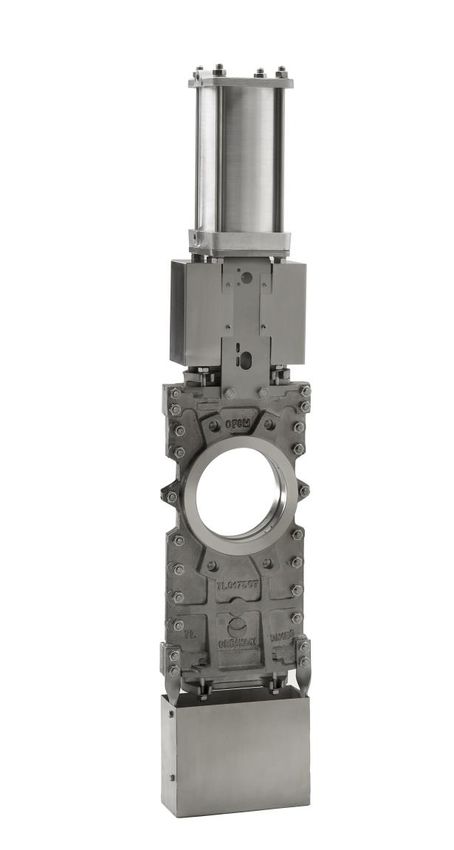
MODEL                  TL

INSTALLATION, OPERATION & MAINTENANCE MANUAL
TL Knife Gate Valve

             0. INTRODUCTION

             1. HANDLING

             2. INSTALLATION

             3. ACTUATORS
               3.1. Handwheel
               3.2. Lever
               3.3. Pneumatic
               3.4. Electric

             4. MAINTENANCE
                4.1. Gland packing replacement
                4.2. Seal replacement
                4.3. PTFE seal replacement
                4.4. Lubrication

             5. STORAGE

             6. ENVIRONMENTAL CONSIDERATIONS

             7. PARTS LIST & DRAWING

        ООО «ТИ-СИСТЕМС» ИНЖИНИРИНГ И ПОСТАВКА ТЕХНОЛОГИЧЕСКОГО ОБОРУДОВАНИЯ
             Интернет: www.tisys.ru www.tisys.kz www.tisys.by www.tesec.ru www.ти-системс.рф
 Телефоны: +7 (495) 7774788, 7489626, (925) 5007155, 54, 65 Эл. почта: info@tisys.ru info@tisys.kz info@tisys.by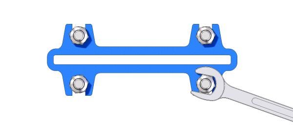
MODEL                   TL

0. INTRODUCTION

           The TL model knife gate is a through-conduit bi-directional wafer valve designed for high
           consistency fluids. The double seat design assures a non-clogging shut off on either normal or
           reverse flow.

           The TL valve complies with the following European directives:

                    • Machinery Directive

           When applicable it can also comply with the following additional directives:

                    • Pressure Equipment Directive

                    • Potentially Explosive Atmospheres (ATEX)

           It is the user’s liability to clearly inform the maximum working conditions (PS, TS), medium (gas
           or liquid) and dangerousness group (1 or 2) and if the fluid is unstable to properly classify the
           valve according the PED directive.

           ORBINOX offers, supplies and certifies valves according to the information received from the
           customer. The customer is liable to make sure this information is accurate and according to
           specific working conditions requirements where the valve will be installed.

           For EU Directives and other Certificates, please see the document:
           Directives & Certificates Compliance - Knife Gate Valves - IOM

1. HANDLING

            The valves are packed according to the appropriate transport standards. If you receive the
            packing damaged, please inform the transport company in writing and contact you ORBINOX
            representative.

            When handling an ORBINOX valve please pay attention to the following points:

               • DO NOT ATTACH LIFTING GEAR TO THE VALVE ACTUATORS OR GATE GUARDS. They
               are not designed to bear the weight, and could easily be damaged.

               • DO NOT LIFT THE VALVE BY THE VALVE BORE.
               This can cause damage to the seating surfaces and seals.

               • Check that selected lifting gear is rated to carry the weight of the valve. The valve can be
               handled using eyebolts, soft straps or slings.

        ООО «ТИ-СИСТЕМС» ИНЖИНИРИНГ И ПОСТАВКА ТЕХНОЛОГИЧЕСКОГО ОБОРУДОВАНИЯ
             Интернет: www.tisys.ru www.tisys.kz www.tisys.by www.tesec.ru www.ти-системс.рф
 Телефоны: +7 (495) 7774788, 7489626, (925) 5007155, 54, 65 Эл. почта: info@tisys.ru info@tisys.kz info@tisys.by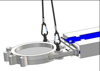
MODEL                  TL

               • EYEBOLTS: make sure the eyebolts have the same thread as the bolt holes and they are all
               well secured. Ideally when using lifting gear to move an ORBINOX valve, it should be
               supported by two or more eyebolts screwed into the tapped fixing holes in the valve body.

               • SOFT STRAPS: with the valve in the closed position, the straps should be placed between
               the gland area and the bore such that the valve is balanced.

          Fig. 1 Handling with eyebolts                             Fig. 2 Handling with soft straps

            PNEUMATIC ACTUATED VALVES (Non-standard valves shall be checked case by case)

            ORBINOX pneumatic valves (with Ø125 cylinder and above) are supplied with 2 lifting lugs
            for a safe handling of the valve for vertical movements

            Handling WARNING:

            Lifting lugs are not machined so they could have sharp corners; soft straps or slings are
            forbidden to be used with these lifting lugs

       ООО «ТИ-СИСТЕМС» ИНЖИНИРИНГ И ПОСТАВКА ТЕХНОЛОГИЧЕСКОГО ОБОРУДОВАНИЯ
            Интернет: www.tisys.ru www.tisys.kz www.tisys.by www.tesec.ru www.ти-системс.рф
Телефоны: +7 (495) 7774788, 7489626, (925) 5007155, 54, 65 Эл. почта: info@tisys.ru info@tisys.kz info@tisys.by
MODEL TL
Below table shows the maximum weight of valve + pneumatic cylinder that 2 lifting lugs can hold
depending on lifting chain angle (X):
With 2 lifting lugs: max. weight valve + cylinder (kg.)
L: minimum lifting chain length
CYLINDER
X: 60° X: 75°
Kg. Lmin (mm) Kg. Lmin (mm)
125 170 130 310 220
160 270 170 500 280
200 390 220 710 380
250 740 300 1335 500
300 1140 360 2030 600
350 1615 440 2835 720
400 2105 500 3660 830
• For horizontal movement, the valve shall be lifted mainly from the body and the yoke. See
above instructions for further instructions
• Cylinder’s lifting lugs can only be used during horizontal movement of the valve to help
balance the valve given the weight is hold at the body lifting point (center of gravity is approx.
centered on the body)
• The valve can be lowered from vertical to horizontal position when it is hanging from the
cylinder’s lifting lugs
ООО «ТИ-СИСТЕМС» ИНЖИНИРИНГ И ПОСТАВКА ТЕХНОЛОГИЧЕСКОГО ОБОРУДОВАНИЯ
Интернет: www.tisys.ru www.tisys.kz www.tisys.by www.tesec.ru www.ти-системс.рф
Телефоны: +7 (495) 7774788, 7489626, (925) 5007155, 54, 65 Эл. почта: info@tisys.ru info@tisys.kz info@tisys.byMODEL TL
Below table shows approximate weight of standard TL pneumatic valves (kg):
DN (mm) CYL. Kg.
DN 50 14
DN 65 16
CYL 100
DN 80 18
DN 100 23
DN 125 34
CYL 125
DN 150 41
DN 200 CYL 160 73
DN 250 105
CYL 200
DN 300 128
DN 350 207
CYL 250
DN 400 300
DN 450 378
DN 500 CYL 300 445
DN 600 619
2. INSTALLATION
For EU Directives and other Certificates, please see the document:
Directives & Certificates Compliance - Knife Gate Valves - IOM
In order to avoid personal injury or damage to property when handling and installing the valve, it
is important to observe the following warnings:
• It is the User’s responsibility to verify compatibility of valve parts materials with the internal fluid
• Qualified and trained personnel must carry out the handling and maintenance of the valve
• Use suitable Individual Protection Equipment (IPE) (gloves, safety footwear...)
• Disconnect all lines affecting the valve and put up a notice notifying that work is being carried
out on the valve
• Isolate the valve completely from the process
• Release process pressure
• Drain the fluid from the valve
ООО «ТИ-СИСТЕМС» ИНЖИНИРИНГ И ПОСТАВКА ТЕХНОЛОГИЧЕСКОГО ОБОРУДОВАНИЯ
Интернет: www.tisys.ru www.tisys.kz www.tisys.by www.tesec.ru www.ти-системс.рф
Телефоны: +7 (495) 7774788, 7489626, (925) 5007155, 54, 65 Эл. почта: info@tisys.ru info@tisys.kz info@tisys.byMODEL TL
Before installation, inspect the valve body and components for any damage that may have
occurred during shipping or storage. Make sure the internal cavities within the valve body are
clean. Inspect the pipeline and mating flanges, making sure the pipe is free of foreign material
and that the flanges are clean.
The TL valve is bi-directional. Both standard (Type A) and reinforced construction (Type B) can
be installed without taking the direction of fluid into consideration.
However, valves provided with a deflection cone (Type C) are unidirectional. It is vital that they
be installed correctly with respect to the direction of the flow. Correct installation is the
responsibility of the user.
Special care should be taken to maintain the correct distance between the flanges and to ensure
that they are parallel to the valve body. Incorrect alignment of the valve can cause
deformations, which can lead to difficulties in operation.
Place the valve between flanges. First tighten the side bolts (1) and then the upper and lower
bolts (2).
ООО «ТИ-СИСТЕМС» ИНЖИНИРИНГ И ПОСТАВКА ТЕХНОЛОГИЧЕСКОГО ОБОРУДОВАНИЯ
Интернет: www.tisys.ru www.tisys.kz www.tisys.by www.tesec.ru www.ти-системс.рф
Телефоны: +7 (495) 7774788, 7489626, (925) 5007155, 54, 65 Эл. почта: info@tisys.ru info@tisys.kz info@tisys.byMODEL TL
The following table shows recommended torque values for the valve fixing bolts and the
maximum depth (T) of blind tapped holes:
DN T PN-10 CL150 (ASME Torque Torque
(mm) (mm) (EN 1092- B16.5/B16.47 (N.m)(1) (N.m)(2)
1/2) Series A)
50-65 11 M16 5/8” - 11 UNC 35Nm 70Nm
80-100 14 M16 5/8” - 11 UNC 35Nm 70Nm
125 14 M16 3/4” - 10 UNC 35Nm 70Nm
150-200 18 M20 3/4” - 10 UNC 70Nm 140Nm
250-300 22 M20 7/8” - 9 UNC 70Nm 140Nm
350 28 M20 1” - 9 UNC 70Nm 140Nm
400 28 M24 1” - 9 UNC 120Nm 235Nm
450-500 32 M24 1 1/8” - 7 UNC 120Nm 235Nm
600 25 M27 1 1/4” - 7 UNC 175Nm 350Nm
Select the recommended torque based on bolt size for other flange drilling patterns.
Make sure that cross-pattern tightening sequence is always followed.
(1) GJL-250 body material. According to EN 1092-2
(2) other body materials. According to EN 1092-1
The valve can be mounted in any position with regard to the pipe. However, it is advisable to
place it vertically in horizontal pipeline (A) if the installation allows it. (Please consult the
technical department at ORBINOX).
With larger diameters (> 300 mm), heavy actuators (pneumatic, electric, etc.), or with the valve
installed horizontally (B) or at an angle (C) on a horizontal pipeline, the installation will require
the construction of suitable supports. (See the following diagram and consult the technical
department at ORBINOX).
ООО «ТИ-СИСТЕМС» ИНЖИНИРИНГ И ПОСТАВКА ТЕХНОЛОГИЧЕСКОГО ОБОРУДОВАНИЯ
Интернет: www.tisys.ru www.tisys.kz www.tisys.by www.tesec.ru www.ти-системс.рф
Телефоны: +7 (495) 7774788, 7489626, (925) 5007155, 54, 65 Эл. почта: info@tisys.ru info@tisys.kz info@tisys.byMODEL TL
A
C C
B B
C* C*
A*
* For these positions please consult ORBINOX.
In vertical pipelines, the construction of suitable supports is always required (for further
information please consult the technical department at ORBINOX).
Once the valve is installed, test that the flanges have been fastened correctly and that all
electrical and/or pneumatic connections have been properly made.
First, operate the valve with no flow in the pipeline. Then test operation and valve seal with flow.
It should be noted that the packing material might settle in shipping/storage, which can cause
minor leakage. This can be remedied by tightening the gland (5) during installation. The nuts
shall be tightened gradually and crosswise until the leakage stops (see the next figure). Check
that there is no metal contact between the glandfollower (5) and the gate (2).
ООО «ТИ-СИСТЕМС» ИНЖИНИРИНГ И ПОСТАВКА ТЕХНОЛОГИЧЕСКОГО ОБОРУДОВАНИЯ
Интернет: www.tisys.ru www.tisys.kz www.tisys.by www.tesec.ru www.ти-системс.рф
Телефоны: +7 (495) 7774788, 7489626, (925) 5007155, 54, 65 Эл. почта: info@tisys.ru info@tisys.kz info@tisys.byMODEL TL
If the glandfollower nuts are pulled to hard, the force needed to operate the valve will increase,
the valve function will be affected and the box packing lifetime will be shortened.
The table below shows the maximun torque value for tightening the glandfollower nuts.
DN Torque (N.m)
50 - 200 15
250 - 300 25
350 - 600 30
700 - 1200 35
Once performance has been tested, the valve can be put into operation.
Approximate weight of the handwheel-operated valve (rising stem):
DN (mm) : kg
DN 50: 12 kg DN 125: 29 kg DN 300: 110 kg DN 500: 372 kg DN 900: 1360 kg
DN 65: 14 kg DN 150: 35 kg DN 350: 174 kg DN 600: 445 kg DN 1000: 1730 kg
DN 80: 16 kg DN 200: 62 kg DN 400: 266 kg DN 700: 891 kg DN 1200: 2110 kg
DN 100: 20 kg DN 250: 89 kg DN 450: 326 kg DN 800: 1760 kg
ООО «ТИ-СИСТЕМС» ИНЖИНИРИНГ И ПОСТАВКА ТЕХНОЛОГИЧЕСКОГО ОБОРУДОВАНИЯ
Интернет: www.tisys.ru www.tisys.kz www.tisys.by www.tesec.ru www.ти-системс.рф
Телефоны: +7 (495) 7774788, 7489626, (925) 5007155, 54, 65 Эл. почта: info@tisys.ru info@tisys.kz info@tisys.byMODEL TL
3. ACTUATORS
For EU Directives and other Certificates, please see the document:
Directives & Certificates Compliance - Knife Gate Valves - IOM
3.1. HANDWHEEL
To open the valve turn the handwheel (12) anticlockwise. To close turn the handwheel
clockwise.
3.2. LEVER
To operate the valve with this device, first loosen the locking clamp located on the top of the
yoke (8). Then either open or close the valve by moving the lever in the desired direction.
Finally, fix the position of the lever with the locking clamp.
3.3. PNEUMATIC
Valves are usually supplied with a double acting pneumatic actuator although, upon request,
we can supply single-acting actuators. In either case the feed pressure can vary between 3,5
and 10 bar. However, the size of the actuator for each valve has been designed for a feed
pressure of 6 bar.
It is essential for a good maintenance of the cylinder that air should be well dried, filtered
and lubricated. Air quality shall fulfil the following requirements:
• ISO 8573-1 Grade 5:4:3 for regular process (ON / OFF services).
• ISO 8573-1 Grade 5:3:3 for regular process at low temperature (-20 °C).
• ISO 8573-1 Grade 3:4:3 for cylinders with positioners.
• ISO 8573-1 Grade 3:3:3 for cylinders with positioners at low temperature (-20 °C)
It is recommended to actuate the cylinder 3-4 times before the start up, once it is installed in
the pipeline.
3.4. ELECTRIC ACTUATOR
Depending on the type or make of the electric actuator, specific instructions (i.e. a
manufacturer’s manual) will be supplied.
ООО «ТИ-СИСТЕМС» ИНЖИНИРИНГ И ПОСТАВКА ТЕХНОЛОГИЧЕСКОГО ОБОРУДОВАНИЯ
Интернет: www.tisys.ru www.tisys.kz www.tisys.by www.tesec.ru www.ти-системс.рф
Телефоны: +7 (495) 7774788, 7489626, (925) 5007155, 54, 65 Эл. почта: info@tisys.ru info@tisys.kz info@tisys.byMODEL TL
4. MAINTENANCE
For EU Directives and other Certificates, please see the document:
Directives & Certificates Compliance - Knife Gate Valves - IOM
The valve must not undergo any modifications without a previous agreement with ORBINOX.
ORBINOX shall not be liable for any damages that may arise due to the use of non original parts
or components
To avoid personal injury or damage to property from the release of process fluid:
• Those in charge of handling and maintenance of the valve must be qualified and trained in
valve operations.
• Use appropriate personal protection equipment (gloves, safety shoes, etc).
• Shut off all operating lines to the valve and place a warning sign.
• Isolate the valve completely from the process.
• Release process pressure.
• Drain the process fluid from the valve.
The only maintenance required is to change the gland packing (5) or the seal (4) if the valve is a
resilient seated type.
The life of these elements will depend on the working conditions of the valve such as: pressure,
temperature, abrasion, chemical action, number of operations, etc.
4.1. Replacement of the gland packing (5):
1. Depressurise the circuit and place the valve in close position.
2. Remove the gate guards (for automatically actuated valves only).
3. Release the spindle or stem (9) from the gate (3). (Photo 1)
4. Loosen the screws of the yoke (8) and remove it (without loosing the actuator).
5. Loosen the nuts of the gland followers (6) and remove them. (Photo 2)
6. Remove the old packing rings (5) and clean the stuffing boxes.
7. Insert the new packing rings (5), making sure that the ring joints alternate (the first on one
side of the gate, the next on the other and so on).
8. Once the necessary packing rings (5) have been inserted, proceed with a steady initial
tightening of the gland followers (6).
9. Place the yoke (8) (with the actuator) and screw it.
10. Fix the stem (9) to the gate (3).
11. Remount the gate guards.
12. Carry out some operations with a loaded circuit and then re-tighten the gland followers (6)
to prevent leakage.
Photo 1 Photo 2
ООО «ТИ-СИСТЕМС» ИНЖИНИРИНГ И ПОСТАВКА ТЕХНОЛОГИЧЕСКОГО ОБОРУДОВАНИЯ
Интернет: www.tisys.ru www.tisys.kz www.tisys.by www.tesec.ru www.ти-системс.рф
Телефоны: +7 (495) 7774788, 7489626, (925) 5007155, 54, 65 Эл. почта: info@tisys.ru info@tisys.kz info@tisys.byMODEL TL
4.2. Replacement of the seal (4) (only applicable to resilient seated valves):
The seat type will depend on the material of the valve.
METAL SEAT SOFT SEAT
Ring
TL GJL250
Body DN 50-600
Seal
Ring
DN 50-150
Seal
TL CF8M
Body Ring Ring
DN 200-600 Seal
Sliders Slider
1. Remove the valve from the pipeline.
2. Remove the gate guards (for automatically actuated valves only).
3. Release the spindle or stem (9) from the gate (3). (Photo 1)
4. Loosen the screws of the yoke (8) and remove it (without loosing the actuator).
5. Loosen the nuts of the gland followers (6) and remove them. (Photo 2)
6. Remove the old packing (5) and the gate (3) and clean the stuffing boxes.
7. Split the two half bodies (1, 2) and clean internally.
8. Remove the seal retainer rings (7) which support the seals (4) (and/or the sliders for the
stainless steel DN≥200 bodies).
9. Remove worn seals (4) (and/or the sliders for the stainless steel DN≥200 bodies) and clean the
seal housing.
10. Re-insert the sliders; ensure that the join is at the top (only stainless steel DN≥200 bodies).
11. Once the new seal (4) has been cut, according to size, insert it into the seal housing ensuring
that the seal join is at the top (only tight shut-off valves) (Photo 3). With stainless steel bodied
valves, make sure that the slider join does not coincide with the seal join. If the seal (4) is PTFE
seal, follow the point 4.3.
ООО «ТИ-СИСТЕМС» ИНЖИНИРИНГ И ПОСТАВКА ТЕХНОЛОГИЧЕСКОГО ОБОРУДОВАНИЯ
Интернет: www.tisys.ru www.tisys.kz www.tisys.by www.tesec.ru www.ти-системс.рф
Телефоны: +7 (495) 7774788, 7489626, (925) 5007155, 54, 65 Эл. почта: info@tisys.ru info@tisys.kz info@tisys.byMODEL TL
Seal lengths (L)
DN (mm) : L (mm)
DN 50: 240 DN 125: 485 DN 300: 1040 DN 500: 1670 DN 800: 2645
DN 65: 290 DN 150: 565 DN 350: 1200 DN 600: 1970 DN 900: 2930
DN 80: 340 DN 200: 720 DN 400: 1355 DN 700: 2330 DN 1000: 3240
DN 100: 410 DN 250: 880 DN 450: 1510 DN 750: 2460 DN 1200: 3900
Photo 3 Photo 4
12. Insert the seal retainer ring (7) by hammering gently around the edge. (Photos 4 and 5)
13. Position the gaskets (15) and the gate (3) between the two bodies.
Lubricate the gate (3) and the inner parts of the slide-way, and then bolt the two bodies together
removing the extra gasket material
14. Finish the assembly, following the steps of the point 4.1.
Photo 5
ООО «ТИ-СИСТЕМС» ИНЖИНИРИНГ И ПОСТАВКА ТЕХНОЛОГИЧЕСКОГО ОБОРУДОВАНИЯ
Интернет: www.tisys.ru www.tisys.kz www.tisys.by www.tesec.ru www.ти-системс.рф
Телефоны: +7 (495) 7774788, 7489626, (925) 5007155, 54, 65 Эл. почта: info@tisys.ru info@tisys.kz info@tisys.byMODEL TL
4.3. Replacement of the PTFE seal (3):
Follow the same procedure as point 4.2 but with following notes:
1. To obtain a tighter shut off in stainless steel valves, the machined housing of the seat is sealed
with plastic glue. This is not necessary in cast iron valves.
With the seal in this position:
2. Make a circle; joining the ends and making a heart-shaped form (see the following diagram).
3. Insert both ends of the seal in the upper side of the machined housing of the seat (adjacent to
the gland follower (6)), and pushing the arched part with a finger, insert the seal into the
housing. If the diameter of the valve is small (DN≤150), a vice can be used.
4.4. Lubrication:
Twice a year, it is recommended to remove the protection cap (14) and fill up the stem protector
(13) halfway with a calcium-based grease with the following characteristics: highly water
resistant, low ash content, and excellent adherence.
ООО «ТИ-СИСТЕМС» ИНЖИНИРИНГ И ПОСТАВКА ТЕХНОЛОГИЧЕСКОГО ОБОРУДОВАНИЯ
Интернет: www.tisys.ru www.tisys.kz www.tisys.by www.tesec.ru www.ти-системс.рф
Телефоны: +7 (495) 7774788, 7489626, (925) 5007155, 54, 65 Эл. почта: info@tisys.ru info@tisys.kz info@tisys.byMODEL TL
5. STORAGE
• For long storage periods keep the valves indoors in a safe and dry place and protect it from any
impact and or vibrations
• Storing temperatures: -10ºC to +40ºC
• Valves must be stored in either full open or full closed position
• For any component installed in the valves, electric motors, solenoid valves, etc, please refer to
their own instructions manuals
6. ENVIRONMENTAL CONSIDERATIONS
• The packaging is made from environmentally friendly materials. Dispose of the packaging
through the available recycling channels
• The valve is designed and manufactured with materials that can be recycled by specialised
recycling firms. Once the life of the product is expired, you have to consider a proper disposal of
the product in order to prevent any negative impact on the environment and allows for the
recycling of valuable commodities
• Please follow the local environmental rules in your country for proper disposal
ООО «ТИ-СИСТЕМС» ИНЖИНИРИНГ И ПОСТАВКА ТЕХНОЛОГИЧЕСКОГО ОБОРУДОВАНИЯ
Интернет: www.tisys.ru www.tisys.kz www.tisys.by www.tesec.ru www.ти-системс.рф
Телефоны: +7 (495) 7774788, 7489626, (925) 5007155, 54, 65 Эл. почта: info@tisys.ru info@tisys.kz info@tisys.byMODEL TL
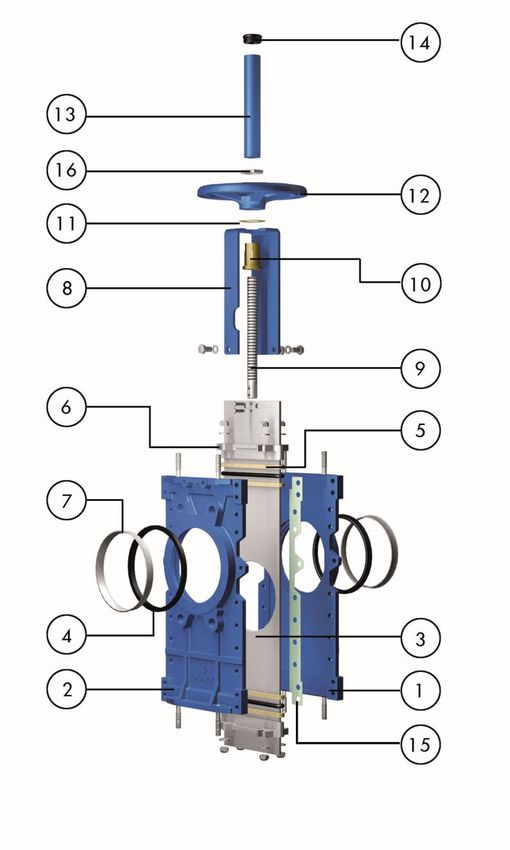
7. PARTS LIST & DRAWINGS
1. BODY 9. STEM
2. COUNTERBODY 10. STEM NUT
3. GATE 11. FRICTION WASHER
4. SEAL 12. HANDWHEEL
5. PACKING 13. STEM PROTECTOR
6. GLAND FOLLOWER 14. CAP
7. SEAL RETAINER RING 15. GASKET
8. YOKE 16. NUT
ООО «ТИ-СИСТЕМС» ИНЖИНИРИНГ И ПОСТАВКА ТЕХНОЛОГИЧЕСКОГО ОБОРУДОВАНИЯ
Интернет: www.tisys.ru www.tisys.kz www.tisys.by www.tesec.ru www.ти-системс.рф
Телефоны: +7 (495) 7774788, 7489626, (925) 5007155, 54, 65 Эл. почта: info@tisys.ru info@tisys.kz info@tisys.byYou can also read