Transient Rotation of Photospheric Vector Magnetic Fields associated with a Solar Flare
←
→
Page content transcription
If your browser does not render page correctly, please read the page content below
Transient Rotation of Photospheric Vector
                                                       Magnetic Fields associated with a Solar Flare
                                               Yan Xu1,2,3, Wenda Cao2,3, Kwangsu Ahn2 , Ju Jing1,2,3, Chang Liu1,2,3, Jongchul
                                                  Chae4, Nengyi Huang1,3, Na Deng1,2,3, Dale Gary3 and Haimin Wang1,2, 3
arXiv:1801.03171v1 [astro-ph.SR] 9 Jan 2018

                                               1
                                                   Space Weather Research Lab, New Jersey Institute of Technology323 Martin Luther King Blvd,
                                                                                Newark, NJ 07102-1982, USA
                                               2
                                                   Big Bear Solar Observatory, New Jersey Institute of Technology , 40386 North Shore Lane, Big
                                                                                Bear City, CA 92314-9672, USA
                                                   3
                                                       Center for Solar-Terrestrial Research,New Jersey Institute of Technology, 323 Martin Luther
                                                                                King Blvd, Newark, NJ 07102-1982, USA
                                               4
                                                   Astronomy Program, Department of Physics and Astronomy, Seoul National University, Seoul
                                                                                151-747, Republic of Korea

                                                                                             January 11, 2018

                                                                                                   Abstract
                                                             As one of the most violent eruptions on the Sun, flares are believed to be powered by
                                                         magnetic reconnection. The fundamental physics involving the release, transfer and deposition
                                                         of energy have been studied extensively. Taking advantage of the unprecedented resolution
                                                         provided by the 1.6-m Goode Solar Telescope, here we show a sudden rotation of vector
                                                         magnetic fields, about 12◦ -20◦ counterclockwise, associated with a flare. Unlike the permanent
                                                         changes reported previously, the azimuth-angle change is transient and co-spatial/temporal
                                                         with Hα emission. The measured azimuth angle becomes closer to that in potential fields
                                                         suggesting untwist of flare loops. The magnetograms were obtained in the near infrared at
                                                         1.56 µm, which is minimally affected by flare emission and no intensity profile change was
                                                         detected. We believe that these transient changes are real and discuss the possible explanations
                                                         in which the high energy electron beams or Alf vén waves play a crucial role.

                                              Introduction
                                              It is well accepted that many solar flares, and other violent eruptions such as coronal mass ejections
                                              (CMEs), result from magnetic reconnection occurring in the corona. However, many manifestations
                                              are visible in the lower solar atmospheres, i.e. the chromosphere and photosphere. In addition to
                                              the radiation, significant changes of the magnetic fields have been observed in the literature 1;2;3;4;5;6 .
                                              Most of them are permanent changes, while transient changes are rarely reported, and are suspected
                                              of being instrumental artifacts.

                                                                                                        1
Permanent magnetic changes are irreversible phenomena of photospheric fields in reaction to
the flare impacts, usually during strong flares greater than M-class. Shear flows measure horizontal
motions of magnetic features along both sides of the magnetic polarity inversion line (PIL). Previ-
ous observations show the spatial correlation between strong shear flow and flare emission 2;7 . More
importantly, shear flow can drop significantly after the flare 3;8;5 , indicating that a certain amount of
magnetic free energy has been released. Tilt angle, also known as inclination angle, is determined
by the ratio between vertical and horizontal magnetic components. During flares, the reconnection
rearranges the topology of magnetic loops and the tilt changes consequently. Direct measurements
of vector fields have shown that horizontal fields increase near the PIL and decrease in the nearby
penumbral regions during flares 9;8;6 . As a consequence, sudden intensity changes of magnetic fea-
tures (usually the penumbra) are observed 1;10;11;12 . Bodily rotation is one of the intrinsic properties
of sunspots or sunspot groups first observed by Evershed (1910) 13 , which are usually gradual and
continue during the entire lifetime. On the other hand, rapid rotations associated with X-class
flares were reported 14;5 and attributed to the torque introduced by the change of horizontal Lorentz
force 15 . Using the data with higher spatiotemporal resolution obtained by the 1.6 m Goode Solar
Telescope (GST, formerly known as the New Solar Telescope 16 ) at Big Bear Solar Observatory
(BBSO, 17 ), the sudden rotation is found to be nonuniform and synchronous with the flare ribbon
propagation 18 .
In contrast to the stepwise temporal profile in permanent changes, the characteristic profile of
a transient change is more like a δ function in time. Transient changes were rarely observed in
the literature. An example is the magnetic anomaly or magnetic transient, a temporal reversal
of magnetic polarities measured simultaneously with flare emission, first reported by 19;20 using
BBSO data. The plausible explanation is that the profile of the Fe i line at 5324 Å, used for the
magnetic measurements, turned from absorption to emission due to the flare heating at lower layers
of solar atmosphere 19 . From space-based observations, magnetic anomalies were reported during an
X5.6 flare observed by the Michelson Doppler Imager on board Solar and Heliospheric Observatory
(SOHO/MDI) 21 and an X2.2 flare observed by the Helioseismic and Magnetic Imager on board
Solar Dynamics Observatory (SDO/HMI) 22 . The authors drew similar conclusions that the polarity
reversal is a consequence of the line profile change. Thus, the magnetic anomaly/transient is not
intrinsic to the Sun, but an artifact in magnetic measurements due to the change of line profile.
In this paper, we present 1.56 µm vector magnetograms with the highest cadence and resolution
ever obtained, which are much less subject to line profile changes, yet reveal a sudden increase of the
azimuth angle. An M6.5 flare was well observed on June 22, 2015 with BBSO/GST using multiple
channels, including the Visible Imaging Spectrometer (VIS) tuned to the Hα line, a Broadband Filter
Imager (BFI) tuned to a continuum near the TiO line at 7057 Å, and the Near InfraRed Imaging
Spectropolarimeter (NIRIS) providing vector magnetograms using the Fe i line at 1.56 µm. The
image scale of vector magnetograms is about 0′′ .083 pixel−1 and the cadence is about 90 s for a full
set of Stokes measurements. The Fe i Stokes profiles are measured at 40 different spectral positions,
which is much higher than that on space-based spectropolarimeters, such as MDI and HMI, and
permits a check of possible changes in line profile due to enhanced emission, which are not seen.
The flare started around 17:39 UT and peaked at 18:23 UT in GOES 1-8 Å soft X-rays. It
lasted for several hours and our interest in this study focuses on the initial phase within the core
region of the flaring areas. The host active region NOAA 12371 was close to the solar disk center
at that time and therefore the geometric projection effect is small and was corrected easily. From
the time sequence of azimuth maps, we clearly see a ribbon-like structure moving co-spatially and
co-temporally with the flare emission in the Hα line. On average, the azimuth angles increased by
2about 12◦ - 20◦ , indicating the local magnetic fields rotated counterclockwise. In contrast to the
permanent changes of magnetic field, the azimuth change is a transient variation, which restored
quickly to its original value after the flare ribbons swept through. By reviewing the existing models,
such as Alf vén waves and induced magnetic fields, we found that they may play important roles
but can not solely explain the observation.
Results
Overview of the Flare
Two major flare ribbons are identified in the core area of the flare. The eastward-moving ribbon
resides in the area of positive magnetic polarity and the westward-moving ribbon propagates in
the region with negative magnetic polarity. We focus on the eastern ribbon, where azimuth angle
increases are much more obvious. A change of azimuth angle can also be identified associated
with the conjugate flare ribbon within negative magnetic fields, but it is dispersed and too weak
to be precisely measured. The elongated flare ribbons represent multiple footpoints of parallel
flare loops. For each individual loop, the change of azimuth angle on its footpoints indicates a
twisting or untwisting of the loop. To determine whether the twist of the loop is increased or
decreased, the difference between the azimuth angles of the measured magnetic field and that of the
extrapolated potential fields are calculated, in which the latter was extrapolated with the Fourier
transformation method 23;24 . As we will see below, the vertical component of magnetic field (Bz )
and the extrapolated potential field (Bp , derived from Bz ), remains nearly constant during the
flare. Therefore, the comparison of transverse components of observed and extrapolated fields,
represented by the azimuth angle, can in principle indicate the variation of the twist.
Characteristics of the Azimuth Angle Variation
The Supplementary Movie S1 shows the time sequence of azimuth angle within a field of view (FOV)
of the flare core region, running from 17:32:35 UT to 18:58:19 UT. It is clear that a ribbon-like
feature propagates from the right to the left. This disturbance of azimuth angle along a narrow
ribbon is co-spatial and co-temporal with the flare emission seen in Hα. In the panel (d) of Figure 1,
a running difference map of azimuth angle is shown at 18:00:12 UT. The dark feature indicated by
the pink arrow represents the change of azimuth angle and the white contours show the leading front
of the Hα emission, indicating a close relationship with precipitating electron beams 25 . The slight
offset of about 300 ∼ 500 km could be a projection effect, because the formation height of Hα is
about few thousand km higher than the formation height of the NIR line at 1.56 µm. Other panels
show the SDO/HMI white light image (panel (a)), an running difference image of Hα blue wing
(−1.0 Å) (panel (b)) and LOS magnetogram derived from NIRIS data (panel (c)). All of the images
are within the same FOV, where the ribbon of interest resides. To examine the azimuth change, we
resolved the 180◦ azimuthal ambiguity in the transverse field using the minimum-energy method 26 ,
and removed the projection effects by transforming the vector magnetogram from observational
image plane to heliographic-cartesian coordinate. Panel (e) presents a time-distance diagram of the
running-difference Hα images. The slit is 3-pixel wide and its position can be found in panel (b).
The bright feature represents the ribbon front of Hα emission, similar to the one in panel (b). In
Panel (f), we display the time-distance diagram of running-difference images of the azimuth angle.
3The slit width is 9 pixels, because the cadence of the vector magnetogram is 90 s, about 3 times of
the cadence of Hα images. The white contour indicates the location of Hα ribbons in panel (e). It
shows a good correlation between Hα emission and azimuth-angle change at different times. Such
a correlation does not vary much at different slit positions.
The characteristic sizes of ribbon-like features are fundamental parameters. For instance, the
ribbon front, which is the precipitation site of electrons, is found to be very narrow 27;28 . We follow
the method described in Xu et al. (2016) 25 and Jing et al. (2016) 27 to measure the width of the
azimuth ribbon, as shown in Figure 2. We use sparse running difference maps (the reference image
is taken several frames prior to the target) to minimize the background noise. On average, the
width of the region of azimuth angle deviation is about 570 km, which is comparable to the size of
the dark ribbon (340 - 510 km) in helium 10830 Å 25 . It is not easy to measure the ribbon length
quantitatively as the ribbon is segmented and noisy near the two ends. We estimate the length
manually using the image taken at 18:00:12 UT and the result is about 13300 km.
Temporal Evolution of the Azimuth Angle Change and Correlation with
Hα Emission
In order to study the temporal evolution of the disturbance, three representative regions (R1, R2
and R3, marked using white color) are selected on the propagating path of the azimuth transient,
as shown in panel (a) of Figure 3. These representative slits are selected in the middle of the ribbon
and away from the sunspot boundary, where the magnetic fields are also affected by the sudden
sunspot rotation 18 in a more gradual manner. The corresponding temporal profiles are plotted in
panel (b). The uncertainties are estimated using the points prior to the initiation of the flare. For
instance, the standard deviation of the first 12 points is used as the error in R1. Let us use R3
as an example. The average azimuth angle suddenly increases by about 20◦ , from the pre-flare
value of 11.7◦ to the flare peak time value of 31.5◦ , with an uncertainty of 6.6◦ . Therefore, the
azimuth peak is significant as it is about three times of the uncertainty. In particular, we see that
the azimuth peak coincides with the Hα emission (dashed curve), based on the results shown in
Figures 1 & 3. For the other two regions, R1 and R2, the horizontal field rotates by 12◦ and 18◦ ,
with uncertainties of 2.5◦ and 5.2◦ , respectively. Using the potential field extrapolation, the azimuth
angle of potential field is determined and plotted as dot-dash curves in panel (b). We see that the
potential field azimuth remains at a certain level above the azimuth angle of the vector fields. Only
at the flare peak time, the measured azimuth angle becomes closer to that in the potential field
due to the sudden rotation. This is a 2D comparison, but is a good proxy of the 3D configuration,
because the extrapolated potential fields are based on the measured vertical component, which did
not vary like the azimuth angle did during the flare. Therefore, the difference of the magnetic
shear between the measured field and the potential field can be represented by the azimuth angle,
which is determined by the horizontal components of Bx and By . In the panels (c) and (d) of
Figure 3, the total magnetic strength and the inclination angle are plotted as a function of time,
respectively. These curves contain noise-induced fluctuations and no impulsive peak is identified
as in the azimuth transient. An area (white box) is selected far away from the flare ribbons and
is used as a reference in comparison to the regions with significant azimuth angle changes. We see
irregular fluctuations but certainly no obvious peak associated with flare emission.
4Discussion
In summary, we present a clear transient change of azimuth angle, associated with propagating
flare ribbons which are footpoints of 3D magnetic loops. The major results are as follows: 1) The
local magnetic vectors rotated about 12◦ to 20◦ simultaneously with flare emission. 2) The strong
correlation between the azimuth transient and flare ribbon front indicates that the energetic electron
beams are very likely to be the cause. 3) The measured azimuth angle becomes closer to that in
the potential field indicating a process of energy release (untwist) of the flare loop.
Firstly, the observed field change is different from the magnetic anomaly reported previously. In
that scenario, the profile of the spectral line used to measure the magnetic fields has changed. In
our case, the line profiles remain in absorption and unchanged during the flare as shown in Figure 4.
It is not surprising as the spectral line used by NIRIS is the Fe i line at 1.56 µm, which is formed
very deep in the photosphere where almost no flare heating can reach except in some extremely
strong flares 29 . In addition, we investigate the polarized raw data before inversion is done. On
the Stokes I, Q, U and V maps as shown in Figure 5, an area similar to R3 is selected and the
corresponding profiles before and during the flare are plotted. As we can see, the Stokes I and V
components, in which V represents the circular polarization and determines the LOS magnetic fields,
remain almost identical. However, the Stokes Q and U components that determine the transverse
fields, vary significantly. Therefore, we believe that azimuth change is real from Stokes Q and U
components and not affected by either flare emission or circular polarizations.
This is the first time that transient field rotation is observed. We attempt to explain the effect
by considering several existing models, which are discussed below.
Magnetic field induced by the electron beams is the most straightforward and intuitive model.
The basic idea is that the penetrating electrons produce induced magnetic fields, which act on the
original fields such that the combined fields point to new directions. This is equivalent to a field
rotation. The downward precipitation of electrons, with negative charges, is equivalent to a upward
current. According to Ampère’s circuit law, self-induced magnetic field is generated around the
ribbon. The ribbon width is much smaller than its length, so the latter can be treated as a half
infinite wall. Therefore, to the left side of the ribbon front, the self-induced magnetic field points to
the south (in solar coordinates) and the overall field will rotate counterclockwise. To the right side,
the overall field will rotate oppositely, which however will be balanced by the self-magnetic field of
the trailing electron beams that have decreased
H but have not been turned off. We can estimate the
required current I using Ampère’s law, B • ds = µ0 I, in which the integration loop is 2l (two
times the ribbon length, which is about 2 × 10⁷ m). In order to induce a magnetic field of order
100 G, the required current is about 1.6 × 10¹¹ A, or an electron flux of 1030 s−1 , a tiny fraction of
the total electron flux (∼ 1035 ) with energy greater than 20 keV derived from the RHESSI HXR
spectra. Whether the azimuth angles of the combined fields increase or decrease is determined by
the relative orientation between the original fields and the flare ribbon. If this angle is larger than
90◦ , an increase is seen in front of the flare ribbon. The rotation effect is cancelled out behind
the flare ribbon by the following opposite rotation effect. Since the fields point outward from a
sunspot center, when the ribbon passes through the sunspot, the relative orientation changes and
the azimuth angle should decrease. However, such a increase-decrease pattern is not observed.
Although the magnitude of induced field matches with observations, the direction does not match.
The second model considers the effect by downward-drafting plasma 30 , which in our case is the
precipitating electron beams. The authors modeled a scenario in which the cooling plasma moving
down from the top of hot granules amplifies the magnetic twist when entering into denser layers,
5which is similar to our case. However, we see the flare loops become less twisted. Nevertheless, this
model suggests that the hydrodynamic effects may be coupled with electrodynamic effects to affect
the pre-flare magnetic fields.
By analyzing and modeling the Hα and Hβ data, Hénoux and Karlický, (2013) 31 found that
emission lines can be polarized linearly by multiple effects, such as electron beams, return current
and filamentary chromospheric evaporation. They found the degree of linear polarizations was about
3 ∼ 9%. However, in our case, there was no emission detected in the NIR line at 1.56 µm. The
NIR line intensity profile remains in absorption during the flare. In addition, the azimuth change,
or say the enhanced linear polarization was only found in front of the propagating flare ribbons in
our event. But the polarized signal was identified on both sides of the flare ribbons in Hénoux and
Karlický, (2013) 31 . Therefore, again we cannot draw a conclusion based on their model.
Alf vén waves 32 also have impacts on the magnetic fields. They are well known in heating the
corona 33 , accelerating electrons during flares 34 and solar winds 35 . Alf vén waves can be generated
by magnetic reconnection during flares 36;34 . In open magnetic field regions, for instance in solar
wind, Alf vén waves were found in untwisted field lines both in observations 37 and simulations 38 . For
closed field regions, such as the flare loops, Fletcher et al. (2008) 34 presented the large-scale Alf vén
wave pulses, which accelerate electrons locally. Within non-uniform plasma, Alf vén waves appear
as torsional waves 39 , which can create rotational perturbations of the plasma and the magnetic
fields frozen in the plasma 40 . The perturbations are usually torsional oscillations 41 , which should
appear periodically but were not observed in our event. However, in the deep atmosphere, these
waves can be damped locally by ion-neutral or resistive damping 42 and therefore only the effect of
the initial pulse is observed as a transient event. Alf vén waves are plausible candidates, but most
previous modeling was done for coronal flux tubes and no quantitatively description is available for
their effects on photospheric magnetic fields.
In conclusion, the observed field change cannot be explained by existing models. The new,
transient magnetic signature in the photosphere that we describe in this paper offers a new diagnostic
for future modeling of magnetic reconnection and the resulting energy release. Such observations
require high cadence and high resolution. Our results motivate further observations using GST and
the Daniel K. Inouye Solar Telescope (DKIST) in probing the mystery of solar flares.
Methods
Magnetic Inversion
After dark and flat field correction, The crosstalk is removed by measuring the effect of optical
elements from the telescope to the detector. Pure states of polarization are fed into the light path
and their response at the detector tells how the incoming polarization from the Sun would be changed
by the optics 43 (and references therein). After careful elimination of the crosstalk among Stokes
Q, U, and V, the NIRIS data undergoes Milne-Eddington inversion to fit the Stokes line profiles
based on an atmospheric model. The source function with respect to optical depth is simplified to
a 1st order polynomial. As results, several key physical parameters can be extracted - Btot , azimuth
angle, inclination, Doppler shift, and so forth. For successful fitting into ME-simulated profiles,
initial parameters are pre-calculated to be in proximity to the observed Stokes profiles. This code
was specifically designed for BBSO/NIRIS and written by Dr. Jongchul Chae using IDL language.
6180◦ Ambiguity Correction
In order to streamline the analysis of vector magnetogram data, data processing tools have been
developed and implemented, including the 180◦ ambiguity resolution and NLFF coronal magnetic
field extrapolation. The 180◦ azimuthal ambiguity in the transverse magnetograms is resolved using
the minimum-energy algorithm that simultaneously minimizes both the electric current density J
and the field divergence |∇ · B| 26 . Minimizing |∇ · B| gives a physically meaningful solution and
minimizing J provides a smoothness constraint. A magnetogram is first broken into small sub-
areas with which to compute a force-free α parameter. Then a linear force-free field is effectively
constructed with which to infer the vertical gradients needed to minimize the divergence. Since
the calculation of J and |∇ · B| involves derivatives of the magnetic field, the computation is not
local, the number of possible solutions is huge and the solution space has many local minima.
The simulated-annealing algorithm 44 is used to find the global minimum. This minimum-energy
algorithm is the top-performing automated method among present state-of-art algorithms used for
resolving the 180◦ ambiguity 45 .
Acknowledgements
We thank the BBSO and SDO/HMI teams for providing the data. The BBSO operation is supported
by NJIT, US NSF AGS 1250818 and NASA NNX13AG14G grants, and the GST operation is partly
supported by the Korea Astronomy and Space Science Institute and Seoul National University, and
by the strategic priority research programme of CAS with Grant Number XDB09000000. This
work is supported by NSF under grants AGS 1250818, 1348513, 1408703 and 1539791; and by
by NASA LWSTRT grants NNX13AF76G and NNX13AG13G, HGI grants NNX14AC12G and
NNX16AF72G. W. Cao was supported by NSF AGS-0847126. D.E.G. was supported by NSF
AST-1615807. J. Chae was supported by the National Research Foundation of Korea (NRF2012
R1A2A1A 03670387).
References
[1] Wang, H. et al. Rapid Changes of Magnetic Fields Associated with Six X-Class Flares. ApJ
576, 497–504 (2002).
[2] Yang, G. et al. Photospheric Shear Flows along the Magnetic Neutral Line of Active Region
10486 prior to an X10 Flare. ApJ 617, L151–L154 (2004).
[3] Tan, C., Chen, P. F., Abramenko, V. & Wang, H. Evolution of Optical Penumbral and Shear
Flows Associated with the X3.4 Flare of 2006 December 13. ApJ 690, 1820–1828 (2009).
[4] Fisher, G. H., Bercik, D. J., Welsch, B. T. & Hudson, H. S. Global Forces in Eruptive Solar
Flares: The Lorentz Force Acting on the Solar Atmosphere and the Solar Interior. Sol. Phys.
277, 59–76 (2012). 1006.5247.
[5] Wang, S., Liu, C., Deng, N. & Wang, H. Sudden Photospheric Motion and Sunspot Rotation
Associated with the X2.2 Flare on 2011 February 15. ApJ 782, L31 (2014). 1401.7957.
7[6] Burtseva, O., Martı́nez-Oliveros, J. C., Petrie, G. J. D. & Pevtsov, A. A. Hard X-Ray Emission
During Flares and Photospheric Field Changes. ApJ 806, 173 (2015). 1505.00509.
[7] Deng, N. et al. Multiwavelength Study of Flow Fields in Flaring Super Active Region NOAA
10486. ApJ 644, 1278–1291 (2006).
[8] Wang, S. et al. Response of the Photospheric Magnetic Field to the X2.2 Flare on 2011
February 15. ApJ 745, L17 (2012). 1112.3948.
[9] Yurchyshyn, V., Wang, H., Abramenko, V., Spirock, T. J. & Krucker, S. Magnetic Field, Hα,
and RHESSI Observations of the 2002 July 23 Gamma-Ray Flare. ApJ 605, 546–553 (2004).
[10] Wang, H. et al. Rapid Penumbral Decay following Three X-Class Solar Flares. ApJ 601,
L195–L198 (2004).
[11] Wang, H., Liu, C., Jing, J. & Yurchyshyn, V. Successive Flaring during the 2005 September
13 Eruption. ApJ 671, 973–977 (2007).
[12] Liu, C. et al. Rapid Changes of Photospheric Magnetic Field after Tether-cutting Reconnection
and Magnetic Implosion. ApJ 745, L4 (2012). 1112.3598.
[13] Evershed, J. Radial movement in sun-spots ; second paper. Monthly Notices of the Royal
Astronomical Society 70, 217 (1910).
[14] Anwar, B. et al. Rapid Sunspot Motion during a Major Solar Flare. Sol. Phys. 147, 287–303
(1993).
[15] Hudson, H. S., Fisher, G. H. & Welsch, B. T. Flare Energy and Magnetic Field Variations.
In Howe, R., Komm, R. W., Balasubramaniam, K. S. & Petrie, G. J. D. (eds.) Subsurface
and Atmospheric Influences on Solar Activity, vol. 383 of Astronomical Society of the Pacific
Conference Series, 221 (2008).
[16] Goode, P. R. & Cao, W. The 1.6 m Off-Axis New Solar Telescope (NST) in Big Bear. In Rim-
mele, T. R. et al. (eds.) Second ATST-EAST Meeting: Magnetic Fields from the Photosphere
to the Corona., vol. 463 of Astronomical Society of the Pacific Conference Series, 357 (2012).
[17] Cao, W. et al. Scientific instrumentation for the 1.6 m New Solar Telescope in Big Bear.
Astronomische Nachrichten 331, 636 (2010).
[18] Liu, C. et al. Flare Differentially Rotates Sunspot on Sun’s Surface. Nature Communications
7, 13104 (2016).
[19] Patterson, A. & Zirin, H. Transient magnetic field changes in flares. ApJ 243, L99–L101
(1981).
[20] Zirin, H. & Tanaka, K. Magnetic transients in flares. ApJ 250, 791–795 (1981).
[21] Qiu, J. & Gary, D. E. Flare-related Magnetic Anomaly with a Sign Reversal. ApJ 599,
615–625 (2003).
8[22] Maurya, R. A., Vemareddy, P. & Ambastha, A. Velocity and Magnetic Transients Driven
by the X2.2 White-light Flare of 2011 February 15 in NOAA 11158. ApJ 747, 134 (2012).
1106.4166.
[23] Alissandrakis, C. E. On the computation of constant alpha force-free magnetic field. A&A
100, 197–200 (1981).
[24] Gary, G. A. Linear force-free magnetic fields for solar extrapolation and interpretation. ApJS
69, 323–348 (1989).
[25] Xu, Y. et al. Ultra-narrow Negative Flare Front Observed in Helium-10830 Å Using the 1.6 m
New Solar Telescope. ApJ 819, 89 (2016). 1601.04729.
[26] Metcalf, T. R. Resolving the 180-degree ambiguity in vector magnetic field measurements: The
’minimum’ energy solution. Sol. Phys. 155, 235–242 (1994).
[27] Jing, J. et al. Unprecedented Fine Structure of a Solar Flare Revealed by the 1.6 m New Solar
Telescope. Scientific Reports 6, 24319 (2016).
[28] Sharykin, I. N. & Kosovichev, A. G. Fine Structure of Flare Ribbons and Evolution of Electric
Currents. ApJ 788, L18 (2014). 1404.5104.
[29] Xu, Y. et al. High-resolution observations of multiwavelength emissions during two x-class
white-light flares. ApJ 641, 1210–1216 (2006).
[30] Taroyan, Y. & Williams, T. Magnetic Field Twisting by Intergranular Downdrafts. ApJ 829,
107 (2016).
[31] Hénoux, J. C. & Karlický, M. Flare line impact polarization. Na D2 589 nm line polarization
in the 2001 June 15 flare. A&A 556, A95 (2013).
[32] Alfvén, H. Existence of Electromagnetic-Hydrodynamic Waves. Nature 150, 405–406 (1942).
[33] Srivastava, A. K. et al. High-frequency torsional Alfvén waves as an energy source for coronal
heating. Scientific Reports 7, 43147 (2017).
[34] Fletcher, L. & Hudson, H. S. Impulsive Phase Flare Energy Transport by Large-Scale Alfvén
Waves and the Electron Acceleration Problem. ApJ 675, 1645–1655 (2008). 0712.3452.
[35] Matsumoto, T. & Suzuki, T. K. Connecting the Sun and the Solar Wind: The First 2.5-
dimensional Self-consistent MHD Simulation under the Alfvén Wave Scenario. ApJ 749, 8
(2012). 1109.6707.
[36] Aulanier, G., Pariat, E., Démoulin, P. & DeVore, C. R. Slip-Running Reconnection in Quasi-
Separatrix Layers. Sol. Phys. 238, 347–376 (2006).
[37] Gosling, J. T., Skoug, R. M., McComas, D. J. & Smith, C. W. Direct evidence for magnetic
reconnection in the solar wind near 1 AU. Journal of Geophysical Research (Space Physics)
110, A01107 (2005).
9[38] Linton, M. G. & Longcope, D. W. A Model for Patchy Reconnection in Three Dimensions.
ApJ 642, 1177–1192 (2006). astro-ph/0509348.
[39] Van Doorsselaere, T., Nakariakov, V. M. & Verwichte, E. Detection of Waves in the Solar
Corona: Kink or Alfvén? ApJ 676, L73 (2008).
[40] Shestov, S. V., Nakariakov, V. M., Ulyanov, A. S., Reva, A. A. & Kuzin, S. V. Nonlinear
Evolution of Short-wavelength Torsional Alfvén Waves. ApJ 840, 64 (2017). 1705.02790.
[41] Mathioudakis, M., Jess, D. B. & Erdélyi, R. Alfvén Waves in the Solar Atmosphere. From
Theory to Observations. Space Science Reviews 175, 1–27 (2013). 1210.3625.
[42] Emslie, A. G. & Machado, M. E. The heating of the temperature minimum region in solar
flares - A reassessment. Sol. Phys. 64, 129–134 (1979).
[43] Elmore, D. F. Polarization Calibration of the Advanced Technology Solar Telescope. In Na-
gendra, K. N., Stenflo, J. O., Qu, Q. & Samooprna, M. (eds.) Solar Polarization 7, vol. 489 of
Astronomical Society of the Pacific Conference Series, 279 (2014).
[44] Kirkpatrick, S., Gelatt, C. D. & Vecchi, M. P. Optimization by Simulated Annealing. Science
220, 671–680 (1983).
[45] Metcalf, T. R. et al. An Overview of Existing Algorithms for Resolving the 180o Ambiguity
in Vector Magnetic Fields: Quantitative Tests with Synthetic Data. Sol. Phys. 237, 267–296
(2006).
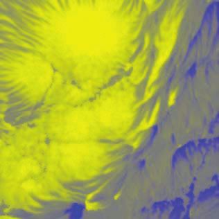
10Figure 1: Azimuth angle changes in association with flare emission
200 200
-37000 30000
62000
18:00:00 UT 18:00:12 UT
N-S Direction [arcsecond]
N-S Direction [arcsecond]
190 190
8000
180 180
Intensity [count]
Intensity [count]
170 170
160
(a) SDO/HMI White Light
160
(b) Running Difference Map
in H-alpha Blue Wing
65 75 85 95 105 65 75 85 95 105
E-W Direction [arcsecond] E-W Direction [arcsecond]
200 200
2500
18:00:12 UT 18:00:12 UT
N-S Direction [arcsecond]
N-S Direction [arcsecond]
190 190
-2500
180 Magnetogram [G] 180
170 170
Running Difference Map
160
(c) GST/NIRIS LOS
Magnetogram 160
(d) of azimuth angle
65 75 85 95 105 65 75 85 95 105
E-W Direction [arcsecond] E-W Direction [arcsecond]
100 100
-25000 43000
Time–Distance Diagram Time–Distance Diagram
Position Along Slit [pixel]
Position Along Slit [pixel]
in H-alpha Difference of Azimuth Difference
75 75
50 50
Intensity [count]
25 25
0
(e) 0
(f)
17:50 17:55 18:00 18:05 17:50 17:55 18:00 18:05
Time (UT) Time (UT)
Figure 1: All of the four images (first and second rows) were taken simultaneously at the flare peak
time ( 18:00 UT) in a common FOV of 40′′ by 40′′ . Panel (a): SDO/HMI white light map. Panel
(b): Running difference image in Hα blue wing (-1.0 Å), showing the eastern flare ribbon. The
bright part is the leading front and the dark component is the following component. Panel (c):
GST/NIRIS LOS magnetogram, scaled in a range of -2500 (blue) to 2500 G (yellow). Panel (d):
Running difference map of azimuth angle generated by subtracting the map taken at 17:58:45 UT
from the one taken at 18:00:12 UT. The dark signal pointed to by the pink arrow represents the
sudden, transient increase of azimuth angle at 18:00:12 UT. The white contours outline 60% of the
maximum emission of the Hα ribbon front. Panel (e): Timedistance diagram of Hα difference maps.
The slit position is shown in panel (b). The time period is from 17:50 UT to 18:05 UT. Panel (f):
Timedistance diagram of azimuth difference maps. The slit position is shown in panel (d). The time
period is from 17:50 UT to 18:05 UT. The white contours outline 15% of the maximum emission of
the Hα ribbon front in panel (e).
11Figure 2: Characteristic sizes of the region of azimuth angle deviation
Running-Difference of Azimuth Angle Running-Difference of Azimuth Angle Running-Difference of Azimuth Angle
200 200 200
(a) (b) (c)
N-S Direction [arcsecond]
N-S Direction [arcsecond]
N-S Direction [arcsecond]
190 190 190
180 180 180
170 170 170
18:00:12 UT
18:00:12 UT 18:01:39 UT
18:01:39 UT 18:03:07 UT
18:03:07 UT
160 160 160
65 75 85 95 105 65 75 85 95 105 65 75 85 95 105
E-W Direction [arcsecond] E-W Direction [arcsecond] E-W Direction [arcsecond]
2 2 2
(e) (f) (g)
Normalized Azimuth Angle
Normalized Azimuth Angle
Normalized Azimuth Angle
1 1 1
0 0 0
-1 -1 -1
FWHM = 478 18 Km FWHM = 794 67 Km FWHM = 474 54 Km
-2 -2 -2
0 15 30 45 60 0 15 30 45 60 0 15 30 45 60
Pixel Along Slit Pixel Along Slit Pixel Along Slit
2 2
(h) (i) (j)
Normalized Azimuth Angle
Normalized Azimuth Angle
Normalized Azimuth Angle
2
1 1
1
0 0
0
-1 -1 -1
FWHM = 610 27 Km FWHM = 569 45 Km FWHM = 514 39 Km
-2 -2 -2
0 15 30 45 60 0 15 30 45 60 0 15 30 45 60
Pixel Along Slit Pixel Along Slit Pixel Along Slit
Figure 2: Panels (a) - (c): Sparse running-difference maps of azimuth angles, taken at three repre-
sentative times. Panels (d) - (f): Azimuth angle profiles along the top slit shown in each image in
panels (a) - (c) and the corresponding Gaussian fits. Panels (g) - (i): Azimuth angle profiles along
the lower slit shown in each image in panels (a) - (c) and the corresponding Gaussian fits. The
FWHM, derived from the fitting, is used as the ribbon width of azimuth change, which is about
570 km on average.
12Figure 3: Temporal evolution of azimuth angle deviation
Azimuth Angle Temporal Variation of Azimuth Angles
200 0 100 1.0
R1
R1 90 270 80
N-S Direction [arcsecond]
R2 Hα(R1) 0.8
Azimuth Angle [degree]
190
Hα Nomalized Count
180 60
R3 Hα(R2) 0.6
40
180 R2
20 0.4
170 0
Ref Hα(R3) 0.2
17:32:35 UT
17:32:35 UT -20 R3
160
(a) (b) Ref 0.0
65 75 85 95 105 17:30:00 18:00:00 18:30:00 19:00:00
E-W Direction [arcsecond] (a) Time [UT]
2200 150
2000 R3 140
Inclination Angle [degree]
130 R3
1800
Total B [G]
120
1600
R1 110
1400 R2
R2 100 R1
1200 90
(c) (d)
1000 80
17:30:00 18:00:00 18:30:00 19:00:00 17:30:00 18:00:00 18:30:00 19:00:00
Time [UT] Time [UT]
Figure 3: Panel (a): Azimuth angle map taken before the flare at 17:32:35 UT. Three slits are
put on the regions of interest (R1-3), plus a reference region in the lower right corner. The white
contours outlines the sunspot umbral areas (>1800 G). Panel (b): The curves with error bars are
the temporal variation of averaged azimuth angle within regions of R1-3. The uncertainties are
estimated using the standard deviation of the pre-flare data points. The peaks are more than three
times of the uncertainties render themselves statistically significant. The flare time is determined
by the Hα light curve, for instance the dashed line is the Hα light curve of R3, in which the peak
matches with azimuth angle peak in R3. All Hα light curves are in natural log space and self-
normalized to their peak emission. In the bottom, the temporal variation of the azimuth angle in
the reference region is plotted, which is manually increased by 50◦ to match the plotting range (50◦
- 190◦ ). The dotted-dash curves are the azimuth angles of extrapolated potential fields that remain
certain levels above the azimuth angles of real fields. Panel (c): Temporal variation of averaged
magnetic flux strength within the representative areas. Panel (d): Temporal variation of averaged
inclination within the representative areas.
13Figure 4: Intensity profiles of the NIR line at 1.56µm during the flare
0.59 Normalized Stokes I Intensity 1.0
200 1.0
Hα Nomalized Count
0.9
(b) ROI 1
0.8
N-S Direction [arcsecond]
ROI2
190 ROI3 0.7
0.6
0.5
t0 t1 t2 t3 t4
ROI1 17:30:00 18:00:00 18:30:00 19:00:00
180
Time [UT]
8000
t0
Stokes I [count]
t1
170 7000
t2
t3
17:32:35 UT 6000 t4
160
(a)
5000
(c)
65 75 85 95 105 1564.5 1566.2 1567.9 1569.6 1571.3 1573.0
E-W Direction [arcsecond] Wavelength [nm]
1.0 1.0
Hα Nomalized Count
Hα Nomalized Count
(d) ROI 2 (e) ROI 3
0.8 0.8
0.6 0.6
0.4 0.4
0.2
t0 t1 t2 0.2
t0 t1 t2 t3 t4
17:30:00 18:00:00 18:30:00 19:00:00 17:30:00 18:00:00 18:30:00 19:00:00
Time [UT] Time [UT]
8000 8000 t0
Stokes I [count]
Stokes I [count]
t1
t0
7000 7000 t2
t1
t3
6000 t2 6000 t4
5000
(f) 5000
(g)
1564.5 1566.2 1567.9 1569.6 1571.3 1573.0 1564.5 1566.2 1567.9 1569.6 1571.3 1573.0
Wavelength [nm] Wavelength [nm]
Figure 4: Panel (a): Stokes I component taken at 17:32:35 UT. The intensity is normalized to the
maximum count as shown in the color bar. Three representative areas are mark using white boxes
(ROI1, ROI2 and ROI3). Panel (b): Hα light curve in ROI 1. The vertical lines indicates five
time points before, during and after the flare. The corresponding NIR intensity profiles (Stokes I)
are plotted in Panel (c), from which we see almost identical line profiles indicating that the flare
heating almost has no effect in this deep layer of solar atmosphere. Panel (d): Hα light curve in
ROI 2. The corresponding NIR intensity profiles, at t0, t1 and t2, are plotted in Panel (f). Panel
(e): Hα light curve in ROI 3. The corresponding NIR intensity profiles, at t0, t1 and t2, are plotted
in Panel (g).
14Figure 5: Stokes profiles before and during the flare
10000 6.0%
Stokes I Stokes Q
9000 3.0%
8000
1.5%
7000
6000 0%
(a) (b)
5000 -1.5%
1.0% 10%
Stokes U Stokes V
0% 5.0%
0%
-1.0%
-5.0%
-2.0% (c) (d)
-2.5% -10%
0 10 20 30 40 50 60 0 10 20 30 40 50 60
Wavelength
Figure 5: Stokes components (I, Q, U, & V) taken near R3 before (blue) and during (pink) the
flare. Panel (a): Stokes I. Panel (b): Stokes Q. Panel (c): Stokes U. Panel (d): Stokes V. It is
clear that the Stokes I and V components remains almost unchange but Q and U components are
significantly affected during the flare.
15You can also read