Ultrafast light field tomography for snapshot transient and non-line-of-sight imaging - Nature
←
→
Page content transcription
If your browser does not render page correctly, please read the page content below
ARTICLE
                  https://doi.org/10.1038/s41467-021-22461-0                 OPEN

                  Ultrafast light field tomography for snapshot
                  transient and non-line-of-sight imaging
                  Xiaohua Feng1 & Liang Gao                  1,2,3 ✉

                  Cameras with extreme speeds are enabling technologies in both fundamental and
                  applied sciences. However, existing ultrafast cameras are incapable of coping with extended
1234567890():,;

                  three-dimensional scenes and fall short for non-line-of-sight imaging, which requires a
                  long sequence of time-resolved two-dimensional data. Current non-line-of-sight imagers,
                  therefore, need to perform extensive scanning in the spatial and/or temporal dimension,
                  restricting their use in imaging only static or slowly moving objects. To address these long-
                  standing challenges, we present here ultrafast light field tomography (LIFT), a transient
                  imaging strategy that offers a temporal sequence of over 1000 and enables highly efficient
                  light field acquisition, allowing snapshot acquisition of the complete four-dimensional space
                  and time. With LIFT, we demonstrated three-dimensional imaging of light in flight
                  phenomena with a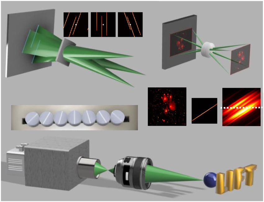
ARTICLE                                                                 NATURE COMMUNICATIONS | https://doi.org/10.1038/s41467-021-22461-0

T
       ime-resolved imaging1,2 plays pivotal roles in a range of             targets18. The inability to cope with extended 3D scenes also
       scientific studies in biology, chemistry, and physics.                 precludes field-deployable NLOS imaging, which needs to
       Despite of its widespread impact and applications, fast               accommodate non-planar or even disconnected surfaces. These
acquisition of large-scale 2D time-resolved data with a picosecond           obstacles make NLOS imaging arguably one of the most chal-
resolution remains a long-standing challenge to solve. To date,              lenging applications for ultrafast cameras.
streak cameras and intensified charge-coupled device (ICCD)                      Here, we present light field tomography (LIFT), an imaging
sensors are parallel detectors of choice for measuring ultrafast             method that is highly efficient in recording light fields and
dynamics. It is, nevertheless, necessary to perform extensive                enables snapshot acquisition of large-scale 2D time-resolved data.
scanning either in the spatial domain (for streak cameras3,4) or             This is achieved by transforming a one-dimensional (1D) sensor
temporal dimension (for ICCDs5) to obtain a 2D time-resolved                 to a 2D light field camera, exploiting the fact conventional light
data, which is an inherently time-consuming process. A single-               field acquisition is highly redundant—the sub-aperture images
photon avalanche diode6 (SPAD), an emerging ultrafast detector               are mostly the same except for disparity cues. The vastly faster
with exceptional sensitivity, can achieve a temporal resolution of           frame rate of 1D sensors also benefits LIFT for high speed ima-
tens of picoseconds and holds great potential to be fabricated in            ging. While prior state-of-the-art ultrafast cameras are severely
large-format two-dimensional arrays7. However, obtaining a                   limited in pixel resolution that prevents light field acquisition,
grayscale time-resolved data still requires temporal scanning or             LIFT offers an elegant way to break this restriction. Coupled with
repeated illuminations with a time correlated single-photon                  a streak camera, LIFT can capture the complete four-dimensional
counter (TCSPC), which leads to an inferior filling factor for 2D             spatiotemporal space in a single snapshot and provide an image
SPAD sensors8 given current fabricating technologies. The need               resolution over 120 × 120 with a sequence depth beyond 1000,
for scanning also undesirably restricts the applicable scope of              enabling unprecedented ultrafast imaging capabilities, including
these cameras to strictly repeatable events.                                 but not limited to, video-rate NLOS imaging using a low
   The past decade has witnessed the development of a plethora of            laser power.
ultrafast cameras capable of 2D time-resolved imaging with a
single snapshot. However, none of these methods attained the                 Results
challenging combination of a deep sequence (of over 1000) and a              LIFT camera. The core idea of LIFT is to reformulate photo-
picosecond temporal resolution, even if active methods are con-              graphy as a computed tomography (CT) problem24 by using
sidered. For instance, using specialized illumination, sequentially          cylindrical lenses to acquire en-face parallel beam projections of
timed all-optical mapping photography (STAMP)1 can achieve a                 the object. The principle is illustrated in Fig. 1a, showing the
temporal resolution of 200 fs, but only a rather limited sequence            transformation of point sources in the object space into parallel
depth (10 s) at each scanning position.             LIFT relates to the en-face object via the Fourier slice theorem
Faster scanning can also be achieved in several other ways:                  after computational resampling. The imaging process can be
shortening the sensor exposure time, reducing the spatial scan-              written as (Methods section):
ning density, or parallelizing acquisition23. Nevertheless, the
scanning mechanism still persists, and the resultant smaller                                                    b ¼ Ag                        ð1Þ
photon counts from shorter exposure typically need to be com-
pensated by using a higher laser power and/or retro-reflective                where b is the measurement data, g is the vectorized

2                NATURE COMMUNICATIONS | (2021)12:2179 | https://doi.org/10.1038/s41467-021-22461-0 | www.nature.com/naturecommunications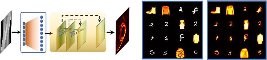
NATURE COMMUNICATIONS | https://doi.org/10.1038/s41467-021-22461-0                                                                         ARTICLE

                              a                          P1         P2       P3         b    1: Pin-hole model
                                  Image plane

                                                                                             2: PSF convolution

                              c                                                                           PSF
                                        Cylindrical lenslet array
                                                                                                                     1D sensor

                                                                           Relay lens
                                                                                                                 3D scene
                                     Streak camera

Fig. 1 Working principle and implementation of light field tomography. a Illustration of image formation by a cylindrical lens. Three point sources in the
object space are transformed into parallel lines on the image plane, producing a projection image. Acquiring such projection images from different
perspectives using lenslets oriented at different angles naturally samples the light field of the 3D scene, as exemplified in the insets P1–P3, where the image
center is highlighted to visualize the disparities. b Two-step modeling of cylindrical lenslet imaging process. For clarity, an image showing predominantly
point-like structures is rendered. The 1D projection data is obtained by sampling the convolution result of the pinhole image and line-shaped PSF. Recording
such 1D data over time yields a time-resolved measurement. c Typical system setup of a LIFT camera. The cylindrical lenslet array is closely secured to the
entrance slit of the streak camera.

two-dimensional (2D) image, and A is the forward operator                            The ultrafast LIFT system configuration is diagrammed in
representing the parallel beam projections at different angles. The               Fig. 1c. Seven customized cylindrical lenslets (diameter, 2 mm;
underlying image can be recovered by inverting the above                          focal length, 8 mm) oriented at distinct angles are assembled on a
equation with a range of methods such as the analytic filtered                     3D printed holder and aligned with the slit of a streak camera.
backprojection24. In theory, one should use as many lenslets as                   The lenslet arrangement—the sequence of the invariant axis’
dictated by the Nyquist sampling criterion for high-quality image                 angles with respect to the slit—can be optimized for different
reconstruction. This is generally impractical for high-resolution                 applications, such as an automatically extended depth of field
2D imaging due to the limited pixel number of 1D sensors.                         (Supplementary Note 3.3). The 3D scene is imaged by a camera
However, under the framework of compressive sensing, the                          lens to the intermediate image space, from which the cylindrical
number of projections required for image reconstruction can be                    lenslet array forms differently projected sub-images onto the slit
substantially reduced.                                                            plane. A field stop at the intermediate image plane reduces the
   A key observation here is that high dimensional data tends to be               field of view to avoid the sub-image overlap between the adjacent
highly compressible27—the spatial image (x, y) at each time                       lenslets. The streak camera relays the 1D projection images from
instance of the spatiotemporal datacube (x, y, t) is far simpler than             the slit onto a photocathode, converts it to the electronic domain,
natural photographs and consequently can be efficiently encoded                    and eventually deflects it onto different rows of a CCD camera
in certain representation bases. Particularly for NLOS imaging, the               according to the photons’ time of arrival. Because the temporal
instantaneous image on the wall can be represented with only                      axis is orthogonal to the 1D projection image, there is no spatial-
~tens of projections for high quality reconstruction of complex                   temporal coupling in LIFT, leading to an optimal temporal
hidden scenes (Supplementary Note 6.2). This particular embodi-                   resolution.
ment renders LIFT similar to sparse view CT28, which generally
requires slower iterative methods for reconstruction and is prone
to degraded image quality in certain scenarios (Supplementary                     Three-dimensional transient imaging. To demonstrate LIFT in
Note 2). To mitigate these two issues, we devised a deep adjoint                  ultrafast imaging, we captured a light-in-flight scene that is
neural network (DANN) to accelerate and improve LIFT image                        beyond the capability of existing ultrafast cameras. A light-
recovery, which incorporates the adjoint operator AT of the system                diffusing fiber31, whose internal nanostructures scatter out a small
into a deep convolutional neural network and thereby avoids the                   fraction of light from its core, was wrapped into a helical shape
blind end-to-end training typical in previous endeavors29. This                   with a depth range stretching over 80 mm (Fig. 2a). After cou-
facilitates the deep neural network to generalize well even when it               pling a picosecond pulsed laser into the fiber, the internal laser
is trained on a small dataset30. The synergy between compressive                  pulse evolution was recorded at 0.5 T frames per second with a
data acquisition and fast deep neural network reconstruction                      native temporal resolution of ~3 ps.
breaks the data bandwidth limit of conventional cameras and                          Spanning a large depth range, it is challenging for cameras with
enables high-resolution 2D imaging with 1D sensors.                               a fixed focus to well resolve the helical fiber. The common wisdom

NATURE COMMUNICATIONS | (2021)12:2179 | https://doi.org/10.1038/s41467-021-22461-0 | www.nature.com/naturecommunications                                   3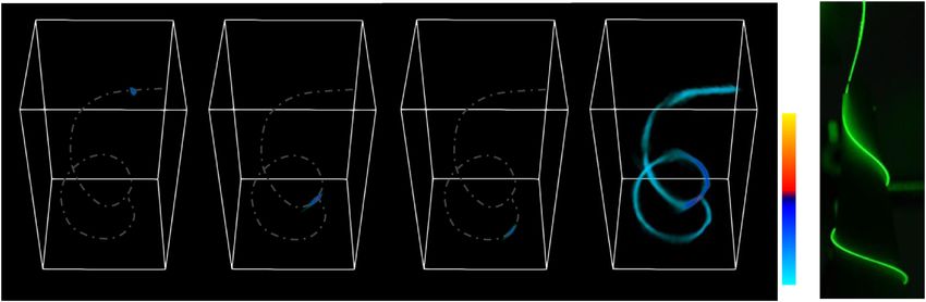
ARTICLE                                                                             NATURE COMMUNICATIONS | https://doi.org/10.1038/s41467-021-22461-0

            a                                                       b   Refocus at 1        Refocus at 2         Refocus at 3   c   All-in-focus
                                                                                                                                             8 mm
                        LIFT camera                                                                                                                 1
                                               1       2     3

                                                                                    1       2                    3                  0               0

            d                                                                                       e                                   f

                            120 ps                         540 ps                       1080 ps

                                                                                                                                    1

                z                              z                            z                            z
                    x                              x                            x                            x          12 mm       0
            y                              y                            y                            y

Fig. 2 Transient light field imaging by a LIFT camera. a Experimental setup. b Post-capture refocusing at different depths. The images are time-integrated
so that all parts of the helical fiber can be rendered, which are otherwise separated at different time instances. c All-in-focus time-integrated imaging
results. d 4D (3D space and time) characterization of a picosecond laser pulse propagating inside a light-diffusing fiber. The helical fiber structure is crafted
and overlaid in each 3D frame for visual guidance. e Time-integrated 3D image of the helical fiber. f Photograph of the helical fiber.

is to reduce the camera’s aperture for an extended depth of field,                       mitigating the system’s implementation limitations. Specifically,
which scales poorly for ultrafast imaging owing to the fundamen-                        DANN can alleviate the limited view problem35, which refers to a
tally limited photon budget at high frame rates. This is illustrated                    degraded tomographic image reconstruction when the projection
in Fig. 2b, which shows the fiber images obtained at different focal                     data does not span the complete angular range of [0o, 180o]. As
settings, emulated by computationally refocusing the LIFT camera                        analyzed in Supplementary Note 2, though not inevitable, a fre-
at different depths and integrating time-resolved images along the                      quency cone along the ky direction in the k-space is not sampled
temporal axis. For each preset focal depth, only part of the helical                    in our current LIFT camera. This is manifested in the all-in-focus
fiber remains sharp, as indicated by the arrows, and ghost images                        image of the helical fiber in Fig. 2c: the horizontal features on the
begin to emerge for heavily defocused parts (Supplementary                              top and bottom parts show an inferior resolution and conse-
Note 3.1). In striking contrast, LIFT can synthesize an all-in-focus                    quently appear dimmer. However, by training the DANN with a
image (Fig. 2c) to resolve the entire helical fiber structure by                         dataset containing similar challenging cases, the network can
leveraging its post-capture refocusing capability (Supplementary                        efficiently learn and mitigate this problem.
Note 3.2). With seven angular components herein, LIFT can                                  To demonstrate our approach, we changed the cylindrical
effectively increase the depth of field by seven folds, which is                         lenslet arrangement for an automatically extended depth of field
notably achieved without compromising light throughput.                                 (dubbed as depth-of-field version in Supplementary Note 3.3) and
   Moreover, LIFT enables the extraction of the scene depth at                          trained the DANN network for the system using an image set
each time instant via the depth-from-focus32 method, thereby                            collected from MNIST36 and FashionMNIST37 dataset. The
revealing the complete 4D spatiotemporal dimensions of the event                        training set was created such that ~60% of its images contain rich
under observation. For our current implementation, the depth                            spatial frequencies inside the missing cone of the system to enable
retrieval accuracy without the relay system is d2ΔL(Da)−1 ≈ 2 mm                        efficient learning of reconstruction under limited view con-
(Supplementary Note 3.4), with d and a being the distance from                          straints. Figure 3b shows representative DANN reconstructions
the lenslet array to the object and 1D sensor, respectively. The                        for LIFT imaging (no temporal deflection) of an experimental test
lenslet array baseline D and the pixel size ΔL serve similar roles as                   dataset displayed on a monitor. The test dataset was composed
those in stereo methods32: a large baseline and a smaller pixel yield                   primarily with images showing strong features along the
a better depth resolution. After depth extraction and extending                         horizontal direction to illustrate the pessimistic recovery
the depth of field, the 3D imaging of laser pulse propagation inside                     performance for the scenes afflicted by the limited view problem.
the helical fiber is illustrated in Fig. 2d at several representative                    While iterative results tend to blur horizontal features as for the
time instants, and the complete animation is provided in                                helical fiber, the DANN network clearly recovers the images with
Supplementary Movie 1. The retrieved 3D structure of the fiber                           most horizontal features well delineated. More test dataset
(Fig. 2e), obtained by integrating all frames, agrees qualitatively                     comparisons are provided in Supplementary Note 8.
well with the photograph in Fig. 2f, validating LIFT’s capacity in                         The laser pulse propagation inside the helical fiber is re-
visualizing extended 3D objects. Such extended depth of field and                        captured using the automatically extended depth-of-field version
3D imaging capabilities are defining features of LIFT over other 2D                      of LIFT but re-wrapped to emphasize its horizontal features for
ultrafast cameras33,34 (Supplementary Note 7).                                          an escalated limited view problem. The recovered images at
                                                                                        representative time instants by iterative methods and DANN are
Deep adjoint neural network for LIFT reconstruction. The deep                           compared in the first and second row of Fig. 3c (full clips in
adjoint neural network (Fig. 3a) is critical for accelerating the                       Supplementary Movie 2). As the laser pulse propagated to the
reconstruction and improving the image quality by learning and                          horizontal parts (top and bottom), iterative results get dimmer

4                       NATURE COMMUNICATIONS | (2021)12:2179 | https://doi.org/10.1038/s41467-021-22461-0 | www.nature.com/naturecommunications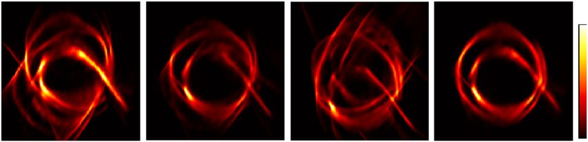
NATURE COMMUNICATIONS | https://doi.org/10.1038/s41467-021-22461-0                                                                    ARTICLE

           a                                                                   b
                               Deep adjoint neural net

                       AT

                                                         …

           c       Frame 60                 Frame 120                 Frame 225                 Frame 390                  DC image

                                                                                                                      8 mm

                   Frame 60                 Frame 120                 Frame 225                 Frame 390                  DC image

                                                                                                                                         1

                                                                                                                      8 mm
                                                                                                                                        0

Fig. 3 Deep adjoint neural network for LIFT reconstruction. a The network architecture of DANN. The measurement data is firstly processed by the
adjoint operator AT of the system and then passed to a convolutional network with skip connections. The detailed network structure and parameters are
provided in Supplementary Note 8. b DANN reconstruction results of a subset of the experimentally measured test images, arranged in a montage format
with an image field of view ~36 mm. Left: ground truth images; Right: DANN reconstruction. c Comparison of image reconstruction results using iterative
methods (top row) and DANN (bottom row). The helical fiber structure is crafted and overlaid in each frame for visual guidance.

whereas the DANN manages to recover the signal decently. The                    >1 m from the wall). The hidden scene was then reconstructed
lack of signals in the iterative reconstruction is more evident in              using the extended phasor-field method (Methods section).
the time-integrated images. Notably, the helical fiber (spanning a                  Figure 4a–c show the experimental imaging results of three
~80-mm depth range) is well resolved here without the need of                   hidden scenes: letter N, a mannequin, and two letters with
computational refocusing, corroborating the automatically                       occlusion. Imaging beyond the wall size is demonstrated in
extended depth of field.                                                         Fig. 4d, e for two hidden scenes, with both lateral and depth
   Currently, the iterative method takes ~2.5 s to reconstruct a                dimension stretching over 1 m. Both the shapes and 3D locations
(128, 128, 1000) datacube when implemented on an RTX2080Ti                      of the scenes are well reconstructed, despite that only seven
graphical processing unit (GPU). By contrast, DANN implemen-                    projections were used in the current LIFT system. Supplementary
ted on the same GPU using PyTorch costs only ~0.5 s after                       Movie 3 illustrates the 3D reconstruction fidelity of the two letters
training (~1.5 h), a five times speedup. The reconstruction speed                at different depths. Supplementary Note 6 present additional
can be further accelerated by efficient scaling of the neural                    results of employing LIFT for imaging complex hidden scenes on
network38 and exploiting more powerful GPUs or alternative                      public synthetic datasets, using different number of projections
hardware like field programmable gate arrays for network                         under various photon budgets. The light field capabilities of LIFT
implementation39.                                                               can substantially lessen the focusing requirement for image
                                                                                acquisition, allowing non-planar walls to be exploited for NLOS
                                                                                imaging. We show in the last column of Fig. 4a–c the degraded
LIFT for non-line-of-sight imaging. Being able to acquire a                     hidden scene reconstruction when the camera refocused away
large-scale 4D data cube (x, y, u(or z), t) with a single snapshot,             from the wall, by undoing the automatically extended depth of
LIFT stands as an enabling method for NLOS imaging at a 30 Hz                   field of LIFT (Supplementary Note 3.3). Although NLOS
video rate, which is critical for applications like navigation and              reconstruction using the phasor-field does not impose any
surveillance. To demonstrate LIFT for NLOS imaging, we focused                  restrictions on the geometry of the relay wall, light collection is
the camera on a diffusing wall with an FOV ~600 mm × 800 mm.                    confined to the lens system’s depth of field for unambiguous
A picosecond pulsed laser was collimated onto the wall, and the                 separation of signals on the wall. As a result, most NLOS
incident spot was blocked by a tiny stop at the relay lens’ inter-              implementations employed a flat/slightly curved wall. Although a
mediate image plane to avoid the directly backscattered light from              depth camera has the luxury of a tiny aperture (thus large depth
the wall. The signals from the hidden scene were recorded by                    of field) to calibrate the imaging geometry, the resultant quadratic
LIFT with a single laser shot. With an average power at 2 mW,                   reduction of light collection prevents similarly small apertures
multiple laser shots were averaged for imaging large static scenes              being used in a NLOS camera. This makes it challenging to
(total acquisition time being 0.2 s using 20 shots for objects placed           accommodate the entire wall within NLOS camera’s depth of field
~0.3 m from the wall and 1 s using 100 shots for objects placed                 in real-world applications. While a recent work used dynamic

NATURE COMMUNICATIONS | (2021)12:2179 | https://doi.org/10.1038/s41467-021-22461-0 | www.nature.com/naturecommunications                            5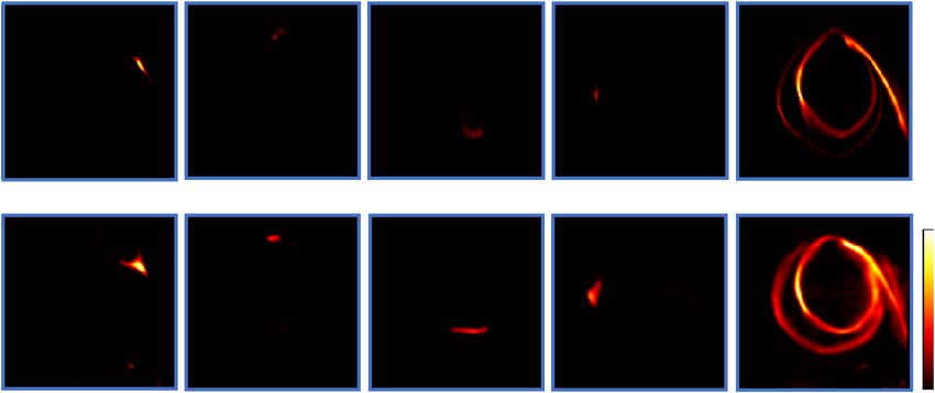
ARTICLE NATURE COMMUNICATIONS | https://doi.org/10.1038/s41467-021-22461-0
3D view Wall view Top view Defocused on wall Reference Top view Wall view
a f
12 cm 12 cm 12 cm 12 cm 12 cm
b
12 cm 12 cm 12 cm 12 cm 12 cm
c
12 cm 12 cm 12 cm 12 cm 12 cm
d e
12 cm 12 cm
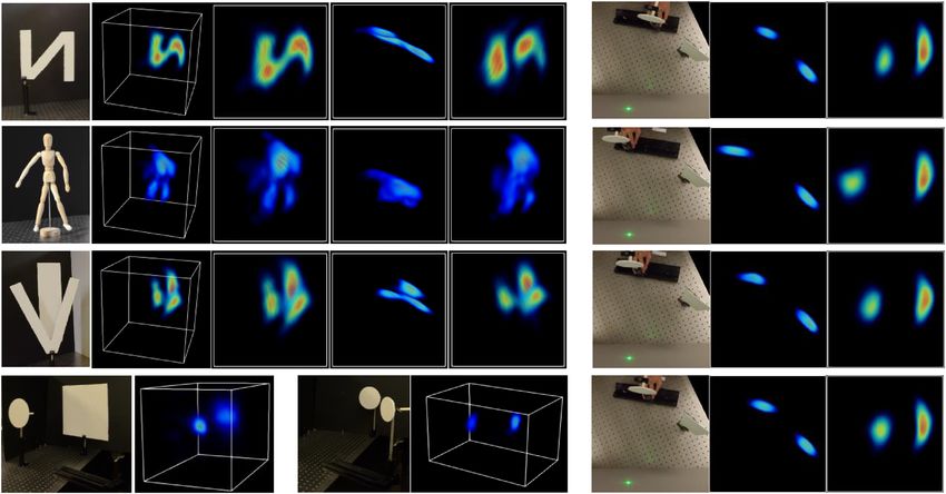
Fig. 4 NLOS imaging by LIFT. a–c Reconstructed images of three static hidden scenes: a letter N, a mannequin, and letters V and I at different depths, with
letter I being partially occluded by V. The mannequin is reconstructed within a smaller volume than others for better visualization. The images from left to
right are the reference photographs, 3D rendering of the reconstructed scenes, and images of the scene from the wall and top perspectives, respectively.
The last column shows the reconstructed scene when the camera is defocused on the wall. d, e imaging over 1-meter scale (beyond the wall size)
using 100 laser shots (total acquisition time of 1 s). The rendering dynamic range is compressed here to emphasize the object at a large distance.
f Representative frames of NLOS imaging of a moving object at a 30 Hz video rate. The dashed arrows indicate the movement direction. The color map
is ‘jet’ with a normalized scale.
walls40, the light collection was still maintained at a stationary factor close to 100%6, allowing more efficient light collection.
point. LIFT’s automatically extended depth of field can potentially LIFT also opens up the possibility to build 2D camera arrays with
lift this restriction without any computational refocusing burden, 1D sensors for ultrafast or synthetic-aperture imaging, featuring
paving the way to efficient light collection over curved or even orders of magnitude smaller data load than conventional
disconnected surfaces. approaches. The larger baseline and etendue in camera arrays will
To showcase video-rate NLOS imaging, we configured a also enable vastly larger light throughput, making it possible to
hidden scene consisting of a static strip and one circular plate, see through occlusions41.
which was mounted on a rail track (~0.3 m from the wall) and Given its unique snapshot acquisition of a large-scale time-
manually translated back-and-forth by about 150 mm within 3 s resolved light field data, LIFT may find a broad range of appli-
across the wall (the moving speed being ~120 mm/s or ~15% of cations that are previously hindered by prolonged time-domain
the wall per second). LIFT recorded the 2D time-resolved data measurements, such as imaging into/through scattering medium
with an exposure time of 10 ns at a repetition rate of 100 Hz, and via time domain diffuse optical tomography42. It could also be
three frames were averaged to improve the SNR, yielding a frame readily extended to an optical dimension other than time, such as
rate of ~30 Hz. Figure 4c shows the recovered dynamic scene at spectral domain by using an imaging spectrometer as the 1D
different time instants along with corresponding reference sensor and thereby enabling snapshot light field hyperspectral
photographs. LIFT captured the motion of the circular plate imaging. With spectral encoding being the foundation of active
faithfully as compared with the reference camera. The corre- ultrafast cameras1, spectral domain LIFT may turn an off-the-
sponding video is provided in Supplementary Movie 4. In shelf imaging spectrometer into an ultrafast camera with sub-100-
contrast to the previous NLOS tracking that uses a limited fs temporal resolution and a sequence depth over 1000, provided
number of virtual sensor points13,15,18 for localizing individual that an appropriate illumination is available.
objects at a few frames per second, LIFT achieved a full 3D
imaging of the hidden scene at 30 Hz, bringing NLOS imaging Methods
closer towards field deployments. LIFT forward model. After resampling, LIFT is mathematically equivalent to
computed tomography using parallel beam projection. Denoting the angle of the
lenslet invariant axis with respect to the 1D sensor’s normal as θ and the local
Discussion coordinate on the sensor behind each lenslet ask, the 1D projection intensity b(k, θ)
Although not experimentally demonstrated, we show extensive can be obtained by first convolving the ideal pinhole image o(x, y) of the en-face
synthetic results in Supplementary Note 6 that LIFT as an ima- object with the line-shaped PSF δ(xcosθ + ysinθ) and then sampling along the slice
y = 0, which leads to:
ging strategy can readily exploit a compact 1D sensor like a 1D
array of SPAD detectors for high quality NLOS imaging at a 30-
ZZ 1
Hz video rate by using only a few rotations while offering unique bðk; θÞ ¼ o x; y δ x cos θ þ y sin θ x¼k;y¼0 ¼ o x; y δ ðx kÞ cos θ þ y sin θ dxdy
1
light field capabilities. SPAD detectors feature three prominent ð2Þ
advantages: a lower cost, a compact form factor, and a single-
photon sensitivity. While 2D SPAD cameras suffer from low fill where δ (x, y) is the Dirac delta function, x and y denote the coordinates in the
factors, 1D SPAD detectors can easily accommodate on-chip image space. It is straightforward to derive from the above equation that projection
photon counters on the side of the active pixel and reach a fill along angle θ is equivalent to rotating the object by an angle of θ and then
6 NATURE COMMUNICATIONS | (2021)12:2179 | https://doi.org/10.1038/s41467-021-22461-0 | www.nature.com/naturecommunications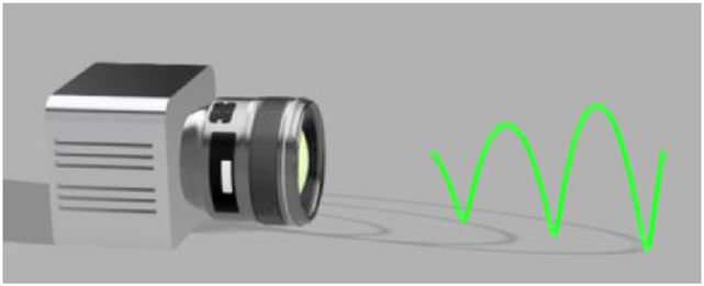
NATURE COMMUNICATIONS | https://doi.org/10.1038/s41467-021-22461-0                                                                                                     ARTICLE

integrating along the y axis:                                                                     Despite the trade-off between the pixel resolution and image quality, LIFT
           Z Z 1                                     Z Z                                      represents a highly efficient method for light field acquisition. Using n projections
                                                         1
 bðk; θÞ ¼        o x0 ; y0 δðx0  k cos θÞdx0 dy0 ¼            o x0 ; y δðx0  k0 Þdx0 dy0
                                                                       0                      of N pixels for reconstructing an N × N image, LIFT acquires implicitly an n × N ×
                   1                                      1                                 N light field data (n angular resolution and N × N spatial resolution) with only n ×
                                                                                        ð3Þ   N pixels, which is N times less than those of conventional (focus or unfocused)
         0   0 T
                                                                                              light field cameras, regardless whether the lenslet number n satisfies the Nyquist
where ½x ; y  ¼ Rθ ½x; y , and Rθ is the rotation matrix. k′ = kcosθ is the
                          T
                                                                                              sampling criterion or not. Given LIFT’s spatial resolution, this fact translates to two
resampling operation as derived in Supplementary Note 1. The above equation can               orders of magnitude more efficient utilization of the camera pixels.
be discretized by sampling the object o (x, y) on a regular N × N grid and                        The field of view of LIFT is reduced by a factor of n, as the 1D sensor is divided
approximating continuous integration with finite summations. The forward model                 to record the object’s projection data at different angles. However, there is no
of the projection data acquisition can then be written as:                                    inherent limit on the achievable field of view for LIFT since it is straightforward to
                                                                                              tailor the relay systems to obtain a desired FOV for target applications.
                                     bðθÞ ¼ TRθ g                                       ð4Þ
in which g is the vectorized object image, Rθ is
                                               the rotation operator, and T denotes           System photon efficiency and signal to noise ratio. LIFT is statistically as
the integration along the column direction of the image. The integration operator T           photon-efficient as conventional cameras. The slit in LIFT is equivalent to a pixel
can model the non-uniform intensity of the line-shaped PSF, a vignetting effect of            array in conventional point-to-point imaging, not an exit/entrance aperture: a
the lenslet, which is small in photographic imaging of LIFT (Supplementary                    larger slit collects more light at the expense of resolution just as the pixel size did in
Note 1). By stacking the projection data at different angles, the forward model for           conventional cameras. Apart from this, the light collection efficiency of LIFT is
LIFT with n lenslets can be completed as:                                                     determined by its line-shaped PSF as analyzed below.
                                      2     3                                                      The PSF in a linear-shift-invariant system satisfies
                                        Rθ1                                                   RR1
                                      6 . 7                                                        1 PSFðx; yÞdxdy ¼ const: ¼ 1 That is, the light from a point source is
                                b ¼ T6    . 7
                                      4 . 5g ¼ Ag                               ð5Þ           distributed onto the sensor according to the PSF, which adds up to a constant (1
                                        Rθn                                                   here without loss of generality). The light intensity I (x0, y0) at pixel (x0, y0) in the
                                                                                              image space could be written as:
here, A is the linear operator representing the system forward model.                                                                            Z Z 1
                                                                                                I ðx0 ; y0 Þ ¼ ½oðx; yÞ  PSFðx; yÞx¼x0 ;y¼y0 ¼       oðx; yÞPSFðx  x0 ; y  y0 Þdxdy
                                                                                                                                                   1
Image reconstruction. Because the number of projections n is generally smaller
than the pixel resolution of the unknown image N, Eq. (5) is under-determined and                                                                                                        ð7Þ
hence represents a sparse view CT problem. We reconstruct the image by solving                where o(x, y) is the object and * denotes the 2D convolution. Hence, each pixel
the following optimization problem:                                                           records a weighted image intensity with a kernel defined by the PSF. For
                                                                                              conventional cameras, the PSF is ideally a Dirac delta function. For LIFT, it is a
                              argmin k b  Ag k22 þρφðgÞ1                               ð6Þ   uniform line spanning over the FOV. Discretizing Eq. (7) and denoting N as the
where φ(g) is a transform function sparsifying the image and :1 is the l1 norm. ρ is a        number of pixels inside PSF, the light collected by an individual pixel is:
hyperparameter that controls the balance between the data fidelity and regular-
                                                                                                                                       o xj ; yj    1 N
ization term. Various transform functions, like total variation, wavelet transform,                                                N
                                                                                                                   I ðx0 ; y0 Þ ¼ ∑j¼1             ¼ ∑ oðxj ; yj Þ            ð8Þ
and discrete cosine transform, can be used to make the image representation                                                               N         N j¼1
sparse. We chose φ(g) = g owing to its simplicity and suitability for a massively
parallel solution. Equation (6) is solved using the FISTA algorithm43 on a GPU for            where PSFðx; yÞ ¼ N 1 has been used. If the object is not spatially sparse along the
optimal speeds. We found LIFT reconstruction to be relatively insensitive to the              line-shaped PSF, the statistically expected light collection efficiency of LIFT will be
regularization parameter ρ: after normalizing the measurement y, setting ρ to                 the same as conventional cameras. For NLOS imaging, the instantaneous images
0.05–0.5 leads to good results for all the experiments. For NLOS imaging, in                  on the wall in NLOS imaging are generally smooth but not spatially sparse,
particular, ρ can span a large range (0.01–0.5) without significant influence on the            especially for complex hidden scenes as shown in Supplementary Note 6.2. As a
reconstruction quality. This is probably attributed to the fact that the recon-               result, the light collection efficiency of LIFT is on par with conventional camera for
struction noises and artefacts on the wall are in the ‘pupil plane’ of NLOS imaging.          NLOS imaging.
    With n projections in LIFT, the complexity for reconstructing a datacube of size              Regarding the total collected light in the image space, LIFT using a 1D array of
(N, N, Nt) using m iterations is O(mnN2Nt). Each iteration includes a gradient step           sensors records a total light of Itot LIFT ¼ ∑Ni¼1 I ðx0 ; y0 Þ ¼ N 1 ∑Ni¼1 ∑Nj¼1 oðxj ; yj Þ,
and a simpler l1 regularization step. The gradient step involves one pass of the              which is N times lessthan that collected by a 2D pixel array:
forward operator A and its adjoint AT, both of which have a complexity of O                   Itot        ¼ ∑Ni¼1 ∑Nj¼1 o xj ; yj . However, each pixel has its own readout and shot
                                                                                                     2D
(nN2Nt): projection at each angle has a complexity of O(N2), and the Nt
instantaneous images are independently processed at n projection angles. The                  noises at the pixel location, elevating the total amount
                                                                                                                                                      of noises in 2D cameras as
regularization step has O(N2Nt) soft shrinkage operations, which is negligible in             well. On a pixel basis, the noise variance is σ 22D ¼ o xj ; yj þ σ 2G (shot noises plus
comparison. Similarly, with a depth resolution of Nd, the reconstruction complexity
                                                                                              readout noises) in a 2D camera and σ 2LIFT ¼ N 1 ∑Nj¼1 oðxj ; yj Þ þ σ 2G in LIFT,
for a 3D scene (x, y, z) is O(mnN2Nd): each depth is reconstructed independently
after shearing the measurement data (Supplementary Note 3).                                   where σ 2G denotes the Gaussian readout noise variance. Therefore, the statistically
                                                                                              expected signal to noise ratio (SNR) of LIFT light collection is on par with
                                                                                              conventional cameras:
Sparsity requirement. The sparsity prior imposed by the regularization term in                                   2               3    2          3    2          3
Eq. (6) may not be valid if the image to be recovered is not sufficiently compact/                                        oðx ;y Þ
                                                                                                                   ∑Nj¼1 Nj j           o xj ; yj         o xj ; yj
compressible in a chosen representation basis. Generally, the image sparsity                     E½SNRLIFT  ¼ E 4               5 ¼E 4            5 E 4            5 ¼ E½SNR2D :
(percentage of dominant coefficients in the basis) must be proportional to the                                         σ LIFT             σ LIFT             σ 2D
inverse of the compression factor (Nn−1: Nyquist sampling rate dividing the system
                                                                                                                                                                                         ð9Þ
sampling rate) in order to achieve a high-fidelity reconstruction. In Supplementary
Note 5.1, we investigated LIFT for imaging scenes of different complexity under
various compression factors by changing the number of projections. With a                     System calibration
compression factor of 18 in our current implementation, LIFT can recover the low              Lenslet array calibration. To determine the angle of the invariant axis of each
frequency structure of cluttered images but not the high frequency details. It is             lenslet with respect to the slit/1D sensor, we installed a pinhole (Thorlabs P100D,
hence important to analyze the sparsity characteristic of the scene to be captured            100 μm diameter) at the center of the image plane, filtering a diffused LED light to
and choose the number of lenslets wisely to strike a balance between the image                emulate a point source. The line-shaped images of the point source were subse-
quality and resolution.                                                                       quently captured by widely opening the slit of the streak camera without applying
                                                                                              temporal shearing. The angles of the lenslets were found automatically using radon
Resolution and field of view. The effective pixel resolution of LIFT is determined             transformation. The center of each sub-image was directly localized from a second
by the 1D sensor pixel number and the number of lenslet. Given n lenslets and a               image of the same point source by reducing the camera slit width to 10 μm. The
1D sensor with Nx pixels, the effective imaging resolution for LIFT is                        projection data length (sub-image size) for each lenslet was then calculated as the
N ¼ n1 Nx cosθmax , where is θmax the maximum projection angle with respect to               average pixel distance between adjacent centers. Finally, the projection data of each
the normal of 1D sensor, and the term cosθmax is to account for the resampling                lenslet was extracted from the 1D sensor to form a sinogram.
process (Supplementary Note 1). There is therefore a trade-off between the pixel
resolution and image quality. The image resolution can be increased by employing              Non-ideal effects calibration. As detailed in Supplementary Note 4, practical
fewer lenslets at the expense of reduced image quality, as the available number of            implementations of LIFT system suffer from non-ideal effect that can be calibrated
projections is proportionally reduced. With seven lenslets along the streak camera’s          to improve image reconstruction quality. No extra data acquisition is needed here:
slit, the effective resolution of current LIFT camera is 128 × 128.                           the point source image obtained for angle calibration suffices.

NATURE COMMUNICATIONS | (2021)12:2179 | https://doi.org/10.1038/s41467-021-22461-0 | www.nature.com/naturecommunications                                                                   7
ARTICLE NATURE COMMUNICATIONS | https://doi.org/10.1038/s41467-021-22461-0
Temporal shearing calibration. Streak camera shows noticeable shearing distortion: Received: 19 October 2020; Accepted: 17 March 2021;
the deflection onto different rows of CCD camera deviates non-uniformly across
the slit from the ideal direction, which is perpendicular to the slit. We measured the
actual temporal shearing by imaging a picosecond laser spot reflected from a
diffusing slab and adding up the sheared images captured at different time delays.
A polynomial transformation was then found to correct the shearing distortion in
streak images prior to any further processing in LIFT. Still, due to the lack of a References
perfect modeling of the shearing distortion, small residual distortion remains that 1. Nakagawa, K. et al. Sequentially timed all-optical mapping photography
slightly degraded the temporal measurement of LIFT using streak camera. (STAMP). Nat. Photon. 8, 695–700 (2014).
2. Goda, K., Tsia, K. K. & Jalali, B. Serial time-encoded amplified imaging for
NLOS experiments. The detailed system layout for NLOS experiments is illu- real-time observation of fast dynamic phenomena. Nature 458, 1145–1149
strated in Supplementary Fig. 9. A picosecond laser (532 nm light at 100 Hz with 6 (2009).
ps pulse width and 2 mW average power) was collimated onto the diffusing wall 3. Velten, A. et al. Femto-photography: capturing and visualizing the
made of a white foam plate. The LIFT camera was focused at the wall with a field of propagation of light. ACM Trans. Graph. 32, 44:1–44:8 (2013).
view of 600 mm × 800 mm. The laser position was fixed around the center of the 4. Heshmat, B., Tancik, M., Satat, G. & Raskar, R. Photography optics in the time
FOV. Ambient room light was turned on during all experiments. dimension. Nat. Photon. 12, 560–566 (2018).
5. Yu, S., Yao, T. & Yuan, B. An ICCD camera-based time-domain ultrasound-
NLOS calibration. The system’s geometric configuration is measured by a switchable fluorescence imaging system. Sci. Rep. 9, 1–14 (2019).
structured-light depth camera. The 3D position of the wall (a dense point cloud), 6. Bruschini, C., Homulle, H., Antolovic, I. M., Burri, S. & Charbon, E. Single-
the laser incident spot and the LIFT camera are all obtained in the coordinate photon avalanche diode imagers in biophotonics: review and outlook. Light
system of the depth camera. To relate each pixel of the LIFT camera to the imaged Sci. Appl. 8, 1–28 (2019).
spot on the wall, a grid pattern is projected on the flat wall and imaged by both the 7. Morimoto, K. et al. Megapixel time-gated SPAD image sensor for 2D and 3D
LIFT and depth camera. The two images are registered by a Homography matrix, imaging applications. Optica 7, 346–354 (2020).
by which a pixel-to-pixel correspondence was established between the LIFT camera 8. Gyongy, I. et al. High-speed 3D sensing via hybrid-mode imaging and guided
and the depth camera. Each pixel’s 3D position on the wall is then identified for upsampling. Optica 7, 1253–1260 (2020).
LIFT camera by indexing the wall’s point cloud using the correspondence map. 9. Gao, L., Liang, J., Li, C. & Wang, L. V. Single-shot compressed ultrafast
photography at one hundred billion frames per second. Nature 516, 74–77
NLOS reconstruction. After reconstructing the 2D time-resolved data, we unwarp (2014).
the data using the calibrated geometric configuration and then reconstructed the 10. Liang, J., Zhu, L. & Wang, L. V. Single-shot real-time femtosecond imaging of
hidden scene with the phasor-field method. To improve noise robustness of LIFT temporal focusing. Light Sci. Appl. 7, 1–10 (2018).
for NLOS imaging, the weighting factors44 are extended to the phasor-field 11. Liang, J. et al. Single-shot real-time video recording of a photonic Mach cone
method. Under the phasor-field framework, the signals yr(rp,t) are convolved with induced by a scattered light pulse. Sci. Adv. 3, e1601814 (2017).
a bandpass-filtering kernel h(t) before backprojection reconstruction (the ima- 12. Faccio, D., Velten, A. & Wetzstein, G. Non-line-of-sight imaging. Nat. Rev.
ginary part is omitted here as it is similarly processed): Phys. 2, 318–327 (2020).
Z w 13. O’Toole, M., Lindell, D. B. & Wetzstein, G. Confocal non-line-of-sight
I ð rv ; t Þ ¼ yr r p ; t hðt τ Þdr p ð10Þ imaging based on the light-cone transform. Nature 555, 338–341 (2018).
w
14. Liu, X. et al. Non-line-of-sight imaging using phasor-field virtual wave optics.
where rp and rv index the detection point on the wall and the reconstruction voxel Nature 572, 620–623 (2019).
r þr 2r
respectively. τ ¼ s pc v is the round-trip travel time from the illumination point 15. Gariepy, G., Tonolini, F., Henderson, R., Leach, J. & Faccio, D. Detection
rs to the voxel rv and back to the detection point. The coherence factor is extended and tracking of moving objects hidden from view. Nat. Photon. 10, 23–26
here on the filtered signals: (2016).
16. Saunders, C., Murray-Bruce, J. & Goyal, V. K. Computational periscopy with
I ðrv ; t ¼ τ þ iΔt Þ
CF ðrv Þ ¼ K 1 ∑Ki¼1 ð11Þ an ordinary digital camera. Nature 565, 472–475 (2019).
Iq ðrv ; t Þ 17. Velten, A. Recovering three-dimensional shape around a corner using ultrafast
Z wn o2 time-of-flight imaging. Nat. Commun. 3, 745–752 (2012).
Iq ðrv ; t Þ ¼ yr rp ; t hðt τ Þ drp ð12Þ 18. Lindell, D. B., Wetzstein, G. & O’Toole, M. Wave-based non-line-of-sight
w imaging using fast f-k migration. ACM Trans. Graph. 38, 116:1–116:13 (2019).
where K is the temporal kernel size, and Δt is the time bin width. It evaluates the spatial 19. Liu, X., Bauer, S. & Velten, A. Phasor field diffraction based reconstruction for
coherence of the signals across the sampling grid: backscattered signals from the hidden fast non-line-of-sight imaging systems. Nat. Commun. 11, 1–13 (2020).
objects are spatially correlated on the wall, whereas noises tend to be independent of 20. O’Toole, M., Lindell, D. B. & Wetzstein, G. ACM SIGGRAPH 2018 Emerging
each other. The reconstruction volume weighted by the coherence factor is then: Technologies 1–2 (Association for Computing Machinery, 2018).
21. Arellano, V., Gutierrez, D. & Jarabo, A. Fast back-projection for non-line of
I ðr v Þ ¼ I ðr v ; t ¼ 0ÞCF ðr v Þ ð13Þ sight reconstruction. Opt. Express 25, 11574–11583 (2017).
The noises are attributed to the measurement shot noises, ambient light, inter- 22. Rapp, J. et al. Seeing around corners with edge-resolved transient imaging.
reflections and LIFT reconstruction artefacts. The ambient light is generally stable Nat. Commun. 11, 5929–5938 (2020).
during the exposure time and can be modeled by a slowly varying function of time. 23. Nam, J. H. et al. Real-time Non-line-of-Sight imaging of dynamic scenes.
Similarly, the inter-reflections tends to show as low frequency components in yr(rp,t). Preprint at http://arxiv.org/abs/2010.12737 (2020).
Therefore, a properly chosen h(t) will effectively attenuate both of them. Their primary 24. Kak, A. C. & Slaney, M. Principles of Computerized Tomographic Imaging
effects are on the measurement shot noises at each time bin, which are determined by (Society for Industrial and Applied Mathematics, 2001).
the total photon count from all origins. 25. Ng, R. Digital Light Field Photography. 203 (Stanford University, 2006).
NLOS reconstruction using the phasor-field method has a complexity of O(N5) or 26. Lumsdaine, A. & Georgiev, T. The focused plenoptic camera. in Proc. 2009
O(N3logN) when implemented with elliptical backprojection or fast Rayleigh- IEEE International Conference on Computational Photography (ICCP) 1–8
Sommerfeld diffraction19. To accelerate computation, we implemented the phasor- (IEEE, 2009).
field reconstruction on a GPU (Nvidia RTX2080Ti) using CUDA. For 3D rendering, 27. Steinbach, M., Ertöz, L. & Kumar, V. The Challenges of Clustering High
the volumetric image was normalized and soft-thresholded to improve visibility. For a Dimensional Data. in New Directions in Statistical Physics: Econophysics,
128 × 128 × 128 volume, the phasor-field reconstruction time is ~2.5 s. Combined Bioinformatics, and Pattern Recognition 273–309 (Springer, 2004).
with the LIFT reconstruction time of 2.5 s using iterative methods (0.5 s using 28. Kudo, H., Suzuki, T. & Rashed, E. A. Image reconstruction for sparse-view CT
DANN) at a resolution of 128 × 128 × 1016, the total time of NLOS imaging is and interior CT—introduction to compressed sensing and differentiated
~5.0 (or 3.0) seconds. As the computing power of GPU continues to grow, the backprojection. Quant. Imaging Med. Surg. 3, 161–161 (2013). 147.
reconstruction speed is expected to enable real-time reconstruction in the near future. 29. Kulkarni, K., Lohit, S., Turaga, P., Kerviche, R. & Ashok, A. ReconNet: Non-
Iterative Reconstruction of Images from Compressively Sensed Measurements.
Data availability in 2016 IEEE Conference on Computer Vision and Pattern Recognition (CVPR)
The experimental data of this study is available at https://github.com/Computational- 449–458 (IEEE, 2016).
Imaging-Hub/LIFT. 30. Maier, A. K. et al. Learning with known operators reduces maximum error
bounds. Nat. Mach. Intell. 1, 373–380 (2019).
31. Glowing Fiber Optic Lighting |Corning Fibrance Light-Diffusing Fiber |
Code availability Corning. https://www.corning.com/opcomm/oem-solutions/worldwide/en/
The code of this study is available at https://github.com/Computational-Imaging-Hub/LIFT. products/specialty-fiber/fibrance-light-diffusing-fiber.html.
8 NATURE COMMUNICATIONS | (2021)12:2179 | https://doi.org/10.1038/s41467-021-22461-0 | www.nature.com/naturecommunicationsNATURE COMMUNICATIONS | https://doi.org/10.1038/s41467-021-22461-0 ARTICLE
32. Schechner, Y. Y. & Kiryati, N. Depth from defocus vs. stereo: how different deep adjoint neural network. L.G. contributed to the conceptual experiments design. All
really are they? in Proc. Fourteenth International Conference on Pattern authors contributed to the manuscript preparation. L.G. supervised the project.
Recognition (Cat. No.98EX170). Vol. 2, 1784–1786 (IEEE Comput. Soc, 1998).
33. Lindell, D. B., O’Toole, M. & Wetzstein, G. Towards transient imaging at
interactive rates with single-photon detectors. in 2018 IEEE International
Competing interests
The authors declare no competing interests.
Conference on Computational Photography (ICCP) 1–8 (IEEE, 2018).
34. O’Toole, M. et al. Reconstructing Transient Images from Single-Photon
Sensors. in Proc. 2017 IEEE Conference on Computer Vision and Pattern Additional information
Recognition (CVPR) 2289–2297 (IEEE, 2017). Supplementary information The online version contains supplementary material
35. Davison, M. E. The Ill-conditioned nature of the limited angle tomography available at https://doi.org/10.1038/s41467-021-22461-0.
problem. SIAM J. Appl. Math. 43, 428–448 (1983).
36. Lecun, Y., Bottou, L., Bengio, Y. & Haffner, P. Gradient-based learning applied Correspondence and requests for materials should be addressed to L.G.
to document recognition. Proc. IEEE 86, 2278–2324 (1998).
37. Xiao, H., Rasul, K. & Vollgraf, R. Fashion-MNIST: a novel image dataset for Peer review information Nature Communications thanks Joshua Rapp and the other,
benchmarking machine learning algorithms. Preprint at http://arxiv.org/abs/ anonymous, reviewer for their contribution to the peer review of this work. Peer reviewer
1708.07747 (2017). reports are available.
38. Tan, M. & Le, Q. V. EfficientNet: rethinking model scaling for convolutional
neural networks. Preprint at http://arxiv.org/abs/1905.11946 (2019). Reprints and permission information is available at http://www.nature.com/reprints
39. Shawahna, A., Sait, S. M. & El-Maleh, A. FPGA-based accelerators of deep
learning networks for learning and classification: a review. IEEE Access 7, Publisher’s note Springer Nature remains neutral with regard to jurisdictional claims in
7823–7859 (2019). published maps and institutional affiliations.
40. Manna, M. L., Nam, J.-H., Reza, S. A., Velten, A. & Velten, A. Non-line-of-
sight-imaging using dynamic relay surfaces. Opt. Express 28, 5331–5339 (2020).
41. Joshi, N., Avidan, S., Matusik, W. & Kriegman, D. J. Synthetic Aperture
Open Access This article is licensed under a Creative Commons
Tracking: Tracking through Occlusions. in Proc. 2007 IEEE 11th International
Attribution 4.0 International License, which permits use, sharing,
Conference on Computer Vision 1–8 (IEEE, 2007).
adaptation, distribution and reproduction in any medium or format, as long as you give
42. Lyons, A. et al. Computational time-of-flight diffuse optical tomography. Nat.
appropriate credit to the original author(s) and the source, provide a link to the Creative
Photon. 13, 575–579 (2019).
Commons license, and indicate if changes were made. The images or other third party
43. Beck, A. & Teboulle, M. A fast iterative shrinkage-thresholding algorithm for
material in this article are included in the article’s Creative Commons license, unless
linear inverse problems. SIAM J. Imaging Sci. 2, 183–202 (2009).
44. Feng, X. & Gao, L. Improving non-line-of-sight image reconstruction with indicated otherwise in a credit line to the material. If material is not included in the
weighting factors. Opt. Lett. 45, 3921 (2020). article’s Creative Commons license and your intended use is not permitted by statutory
regulation or exceeds the permitted use, you will need to obtain permission directly from
the copyright holder. To view a copy of this license, visit http://creativecommons.org/
licenses/by/4.0/.
Author contributions
X.F. and L.G. conceived the study. X.F. designed and built the imaging system, performed
the experiments, analyzed the data, wrote the reconstruction code, and implemented the © The Author(s) 2021
NATURE COMMUNICATIONS | (2021)12:2179 | https://doi.org/10.1038/s41467-021-22461-0 | www.nature.com/naturecommunications 9You can also read