Using a Vector Network Analyzer to Solve Difficult Elevator Problems
←
→
Page content transcription
If your browser does not render page correctly, please read the page content below
CONTINUING EDUCATION

Using a Vector Network Analyzer to Solve Difficult
Elevator Problems
Device can help uncover incompatibilities in elevator equipment that may be causing
chronic motion-controller outages.
by David Herres
    Early 19th-century elevators, which made           redundant telephone lines) to automatically call
multistory buildings feasible, predated electrical     the nearest fire station or other specified location if
distribution systems. These lifts were steam-          smoke were detected in the hoistway, machine
powered and widely used in industrial facilities.      room or nearby.
They required steam engineers, lift operators and          If the elevator system detected a problem with
coal stokers, not to mention the need for cleaning     the car door, or if one of the hallway doors did not
and disposing of ashes. The DC motor in the context    latch securely, power to the motor would be
of the traction elevator was a vast improvement.       interrupted, and the brake would be applied. All
With a few simple electrical controls, the motor’s     this made for greatly enhanced safety and
rotation could be reversed, and its speed regulated,   reliability, overseen by an intricate system of
which was not possible in an AC motor prior to the     electrical sensors, controls and actuators. The
introduction of the variable-frequency drive (VFD)     bottom line is that when something went wrong,
in the 1960s.                                          the computerized motion controller shut down.
    Gradually, throughout the 20th century and         Often, service could be restored merely by resetting
beyond, elevator systems, like automobiles, became     the controller, but this is not always the preferred
more complex, with many improvements making            solution, because the same problem could recur. It
for increased safety and efficiency. First came        is best to find out what went wrong before
automatic controls, replacing the human elevator       resetting the motion controller, though this is not
operator. Then, in the early 1980s, the VFD could      always feasible. For example, when a jet crashes,
control an AC induction motor’s speed, direction       the black box may be destroyed; similarly, data that
and torque. These motors were longer-lasting,          might indicate a path forward may not survive the
required less maintenance and caused less              motion controller outage.
electromagnetic interference due to their brushless        A reasonable approach, then, involves, for a
nature. Around the same time, the elevator motion      start, visually examining wiring and components.
                                                                                                                            Online
controller evolved into its modern form: a digital,    You can open the motion controller cabinet and                Continuing Education

fully programmable computer linked to the              check for charred resistors, melted capacitors, loose
building’s central fire alarm and sprinkler systems    terminations, etc. Sometimes, this will isolate the         Value:
with the ability (through two self-testing,            fault. However, if a component has overheated to
                                                       the point of failure, a question remains: “Was the
                                                                                                                   1 contact hour
                                                       fault intrinsic to the component, or was excessive          (0.1 CEU)
                                                       voltage or loading applied due to an external
         Learning Objectives                           fault?” Also, don’t neglect outside causes such as
                                                                                                                   This article is approved
                                                                                                                   for Continuing
    After reading this article, you should             ambient heat, vibration or excessive demands on             Education by NAEC for
  have learned about:                                                                                              CET®.
                                                       the system.
                                                                                                    Continued
  ♦ Elevator innovations for enhancing
                                                                                                                   EW Continuing
    safety                                                                                                         Education is currently
  ♦ Action the elevator motion controller                                                                          approved in the
    takes when a fault is sensed                                                                                   following states: AL,
                                                                                                                   AR, FL, GA, IL, IN, KY,
  ♦ The best steps to take before setting the
                                                                                                                   MD, MO, MS, MT, OK,
    motion controller                                                                                              PA, VA, VT, WV and WI.
  ♦ The difference between VNA factory and                                                                         Please check for specific
    field calibrations                                                                                             course verification
                                                                                                                   of approval at
  ♦ How the VNA works and what its
                                                                                                                   www.elevatorbooks.com.
    purposes are
                                                       Rohde & Schwarz VNA

                                                                                                          February 2021 • ELEVATOR WORLD      93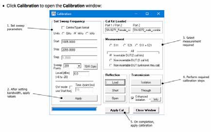
CONTINUING EDUCATION
    This sort of examination may yield quick results, but, more          The vector network analyzer is a costly instrument — more
 often, it leads nowhere, and a more focused approach is             expensive than a high-end digital storage oscilloscope or
 needed. Use of electronic instrumentation is usually in order.      spectrum analyzer. However, Picotech offers a PC-based VNA,
 This can range from a simple neon test light or multimeter,         which consists of a rugged module that connects via USB cord
 oscilloscope, spectrum analyzer and beyond, including the           to the user’s PC. With the company’s software, the instrument
 vector network analyzer (VNA).                                      makes use of the PC’s prodigious processing and display
    According to Rohde & Schwarz’s website (rohde-schwarz.           capabilities to characterize in-circuit devices, components and
 com), the VNA is one of the most essential radio frequency (RF)     transmission lines. This is useful for uncovering
 and microwave approaches. The company offers a wide range           incompatibilities in elevator equipment that may be causing
 of versatile, high-performance network analyzers up to 500 GHz      chronic motion-controller outages.
 with a maximum of 48 ports. These instruments are suitable for
 analyzing passive and active components such as filters,
 amplifiers, mixers and multiport modules.
    Tektronix TTR500 VNA permits the user to take precision
 measurements of all elevator systems, transmission lines and
 individual components. It is designed to measure reflection
 coefficients, impedance, admittance, return loss, insertion loss,
 gain or isolation. The instrument is also suitable for filter
 measurement, antenna matching and tuning, amplifier
 measurements and RF cable and connector measurements,
                                                                     Picotech’s Pico 8.5 GHz VNA connected to a laptop PC
 among many others.
                                                                     Calibration
                                                                         Calibrating the device differs from the more comprehensive
                                                                     factory calibration, performed on sensitive instruments such as
                                                                     the oscilloscope, spectrum analyzer and VNA. Factory
                                                                     calibrations are typically done before the initial purchase and
                                                                     subsequently once a year or as required. They involve sending
                                                                     the instrument back to the manufacturer, where technicians
                                                                     open the enclosure and do whatever it takes to certify the
                                                                     equipment conforms to original specifications.
                                                                         The VNA field calibration, in contrast, is performed by the
                                                                     user prior to each new set of measurements. It is performed
                                                                     entirely at a software level without opening the enclosure and
 Tektronix TTR500 VNA display                                        takes only a few minutes. It is often performed several times a
                                                                     day (whenever accurate measurements are required). The
    Keysight (formerly Agilent and, before that, Hewlett-Packard)    manual provides complete instructions.
 manufactures network analyzers up to 120 GHz, which can be              Following installing the software on a PC, electrical
 extended to 1.5 THz with frequency extenders. Additionally,         connections must be completed. If accurate measurements are
 they offer a handheld VNA up to 50 GHz. Its most advanced           required, both the PC and VNA module should be warmed up
 integrated VNA operates from 10 MHz to 70 GHz (extendable to        for about 30 min.
 1.5 THz). It incorporates three Data Distribution Service sources       Both Pico VNA models (6 and 8.5 GHz) connect via USB cable
 with low spurious emissions and very low phase noise.               to the user-supplied PC. To perform calibration, cables supplied
 Switchable rear-panel jumpers enable signal-conditioning            by the manufacturer are run from Port 1 and Port 2 in the
 hardware or route additional test equipment to the device           module to the device under test. Pico supplies two types of
 under test without the need to move cables.

 Keysight VNA                                                        Pico 6- and 8.5 -GHz VNA calibration connections

94   www.elevatorworld.com • February 2021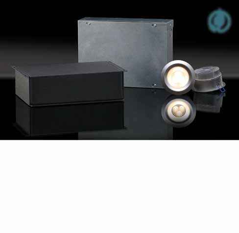
CONTINUING EDUCATION
the time, “networks” were understood to mean
electrical networks: generally, devices, components
and transmission lines.
The Modern VNA
The VNA, as used today, is a general-purpose
instrument that characterizes both linear and
nonlinear devices and components, including such
diverse types as filters, bridges, attenuators, cables,
waveguides, antennae, diodes, transceivers,
oscillators, amplifiers and transistors. Unlike many
electronic instruments, the VNA does not just
measure the device parameters. Instead, it supplies
a signal, usually at high frequency, through a cable
to the input of the device under test (DUT). It then
looks for and times any reflection back through the
Setting VNA field calibration parameters same cable, much in the manner as radar or a
time-domain reflectometer. A time-domain
connectors, called “kits,” that attach to the cables. If the
reflectometer is an electronic instrument used to determine the
insertable device under test has one or two male connectors,
characteristics of electrical lines by observing reflected
use a female connector with a male calibration kit. If the device
waveforms. It can be used to characterize and locate faults in
under test has two male connectors, use female cables and
metallic cables (for example, twisted pair wire or coaxial cable)
identical male kits for both ports.
or to locate discontinuities in a connector, printed circuit board
Then, open the Pico VNA software. In the main menu on the
or any other electrical path.
PC screen, select “Tools and Calibration Kit.” Click “Port 1 Kit,”
The VNA also connects to the output of the DUT and
insert the data for it and click “Apply.” Similarly, click “Load Port
characterizes any response it receives. Moreover, by throwing a
2 Kit,” select the data for it and click “Apply.” The next step is to
switch, the user can have the instrument apply the stimulus to
choose calibration kit(s) appropriate for the device under test.
the DUT’s output, time and characterize reflections, and
For example, if testing a non-insertable device with female
monitor the input.
connectors, use a single female kit for both ports in the VNA
Early VNAs made use of one or more separate, external AFGs,
module.
but increasing miniaturization has enabled manufacturers to
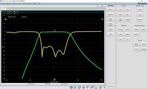
The next phase in the field calibration procedure is setting
include everything in a single enclosure. Above all, the VNA
up calibration parameters. In the main window, click
performs highly accurate measurements of the ratios of
“Calibration.” Then, perform the following steps:
reflected-to-total signal and transmitted-to-total signal.
1) Set the sweep parameters. This is like setting up a spectrum
There are two distinct types of network analyzers. The scalar
analyzer.
network analyzer (SNA) measures and characterizes amplitude
2) Apply the values.
only, while the VNA measures and characterizes amplitude and
3) Select the measurement required.
phase. Currently, VNAs are far more common than SNAs,
4) Perform the calibration steps.
because, in today’s high-frequency electronics, phase shift is
5) Click Apply Calibration.
more likely to occur. It may be intentional (implemented to
The bandwidth setting used during calibration largely
accomplish a definite purpose) or unintentional and requiring
determines the available dynamic range during the
mitigation. In either event, the idea is to detect, measure and
measurement. For fastest speed, choose 10 kHz. Set calibration
precisely categorize phase shift.
power to +0 dBm. Set bandwidth to 140 kHz. For best accuracy
Continued
and about 100 dB in dynamic range, set calibration bandwidth
to 100 Hz. Set calibration power to -3 dBm. Leave bandwidth set
to 100 kHz during measurement.
For general use, fast speed, about 90-dB dynamic range, set
Learning-Reinforcement Questions
calibration bandwidth to 1 kHz. Set calibration power to 0 dBm. Use the below learning-reinforcement questions to study
Leave bandwidth set to 10 Hz during measurement. For best for the Continuing Education Assessment Exam available
dynamic range, set calibration bandwidth to 10 Hz. Set online at www.elevatorbooks.com or on p. 108 of this issue.
calibration power to +6 dBm. Leave bandwidth set to 10 Hz ♦ How are the Pico VNA and PC connected?
during measurement. ♦ Which devices can the VNA characterize?
In all cases, calibration averaging should be set to “None.” ♦ How does the VNA supply signals to the DUT?
The VNA is not directly concerned with computer networks. The ♦ What is the difference between a VNA and an SNA?
term predates computers. The instrument was used in advanced ♦ How can VNA components be mapped without a
electronics laboratories when computers were vacuum-tube schematic diagram?
machines that occupied rows of floor-to-ceiling enclosures. At
February 2021 • ELEVATOR WORLD 95CONTINUING EDUCATION
Unlike many electronic
instruments, the VNA does not
just measure the device
parameters. Instead, it supplies a
signal, usually at high frequency,
through a cable to the input of
the device under test.
speed and to reverse direction. It also varies the motor’s torque
and reports operating status, including temperature and other
parameters, back to the motion controller. All this is done over a
single Ethernet or other low-voltage circuit distinct from the
main power line. This control line runs from the motion
Smith chart controller to the VFD, which is an autonomous unit that may or
High frequency (above the utility-supplied 60 Hz) and phase may not be located within the motion controller cabinet. If an
shift play roles in elevator electronics in two ways that are electrical schematic diagram is not available, one can begin
important to the repair technician and design engineer. These mapping out the component parts by following the heavy
have to do with the following: power lines from the disconnect in the machine room, through
♦ The control circuit for an AC elevator drive motor powered the VFD and to the three-phase drive motor.
by a VFD CAN bus is a serial bus that was covered in your author’s
♦ The ubiquitous Controller Area Network (CAN bus). previous article “CAN Bus for Elevators” (ELEVATOR WORLD,
The VFD is a separate device that, in response to commands June 2017). It was developed beginning in 1983 by Bosch, a large
from an elevator motion controller, permits a standard three- international manufacturer of electronic systems and
phase induction motor to run at higher or lower than rated components and originally intended for automotive
applications, but following its
implementation in the 1991 Mercedes-
Benz W140, it became widely used in
trucks, construction equipment,
aircraft, ships and elevators. CAN bus
serial data transmission is highly
reliable, cost-efficient and tolerant of
electrical noise from outside sources. In
the latest elevator technology, CAN bus
enables serial communication among
the many sensors distributed
throughout an elevator installation,
terminating at the motion controller.
All sensors and actuators, known as
nodes, are connected to the motion
controller by means of twisted-pair
conductors having 120-ohm
characteristic impedance. CAN high
and CAN low signals are either driven
to a dominant state or pulled by
resistors to a recessive state. The
dominant state is encoded by logic 0
and the recessive state by logic 1. Nodes
with lower identifier numbers (IDs)
have priority on the bus.
At low frequencies, the wavelength
of the signal conveyed through the
conductors is invariably far greater
than the circuit length. Thus,
96 www.elevatorworld.com • February 2021CONTINUING EDUCATION
conventional copper or aluminum conductors are adequate for The signal detection block may consist of a diode detector
carrying the power. The wire is sized to have sufficient that converts the RF signal level to a proportional DC level.
ampacity so that current and voltage do not vary between Diode detectors, cheaper than tuned receivers, provide
transmitter and receiver. broadband response. Their broadband response, however, limits
At high frequencies, the signal wavelengths are equal to or sensitivity and makes them prone to spurious signals including
smaller than the conductor length. In this situation, the harmonics. More accurate measurements are obtained by AC
conductors are no longer a pair of wires; instead, they become a detection.
transmission line. The material separating the wires is not Tuned receivers use heterodyne technology, mixing the RF
merely electrical insulation, but a dielectric layer, as in a down to a more user-friendly intermediate frequency (IF). The
capacitor. Rather than a flow of electrons, the signal of interest local oscillator is locked to the RF or IF signal so the receivers
now consists of a succession of traveling waves. This calls for are consistently tuned to the RF signal. Analog-to-digital
entirely different measuring instrumentation. conversion and digital processing extract magnitude and phase
At high frequencies, characterization of networks including information from the IF signal.
devices, components and transmission lines requires The VNA’s display-processor section is where reflection and
measurement of phase and magnitude. Measurement of transmission data are presented to the user. Prominent features
amplitude, as performed by an SNA, is not adequate. are markers; limit lines; pass/fail indicators; linear and log
Phase distortion displayed in the VNA reveals group delay, a formats; and grid, polar and Smith charts. Most of this is
measure of the transit time of a signal through the DUT, self-explanatory, but we will discuss the widely used Smith
juxtaposed with respect to frequency. It is calculated by chart, which figures prominently in the VNA display. The Smith
comparing the phase of the signal at the input to that at the chart is a polar graphical calculator that enables RF engineers
output. Any variation in group delay gives rise to distortion and to solve transmission-line and matching circuit problems.
is likely to show up as poor performance of a given component The chart, devised by Phillip H. Smith (1905-1987) and T.
or circuit. Deviation from linear phase and group delay are Mizuhashi, is used to display electronic parameters such as
measured and displayed in VNA analysis. Group delay is an easy impedances, admittances, reflection coefficients, S-parameters,
way to detect the presence of and quantify phase distortion. noise figure circles, constant gain contours and regions of
An important capability of the VNA is to characterize unconditional stability. Today, software-based methods have
high-frequency networks. Simple voltage and current replaced the physical chart to a great extent, but it still appears
measurements at the device ports do not suffice. This is because in the VNA display and is useful in organizing information
of probe impedance, among other reasons. Also, active devices provided by the instrument. Reflection coefficients can be read
may oscillate or be destroyed when shorts and opens are directly from the chart.
connected to them. Around its circumference is a scale graduated in
A solution was found in the development of scattering wavelengths and degrees. It represents the distance along a
parameters (S-parameters). This refers to gain, loss and transmission line between source and load. The Smith chart
reflection as present in traveling waves. These can be readily uses the standard reflection coefficient formula to develop
measured. It is not necessary to compromise an active DUT by equations for circles with various radii. The Smith chart is an
exposing it to a harmful load. Moreover, the S-parameters of array of circles, each located in a different place relative to the
multiple devices can be tested in cascade. If desired, other plot and each representing constant resistance or constant
parameters can be derived from the S-parameters. These reactance, the parameters that comprise constant impedance.
include:
♦ Admittance parameters (Y-parameters) for linear electrical David Herres holds a New Hampshire Master
networks Electrician’s license and has worked as an
♦ Hybrid parameters (h-parameters) for use with a current electrician in the northern part of that state for
many years. He has focused on writing since
amplifier
2006, having written for such magazines as
♦ Impedance parameters (Z-parameters) to describe the
ELEVATOR WORLD, Electrical Construction and
electrical behavior of linear electrical networks Maintenance, Cabling Business, Electrical Business,
The VNA uses four sections to measure the incident, reflected Nuts and Volts, PV Magazine, Electrical Connection,
and transmitted signals. They are the source for stimuli, Solar Connection, Solar Industry Magazine, Fine
signal-separation devices, receivers that down-convert and Homebuilding Magazine and Engineering
detect the signals, and processor and display for interpreting News-Record. He has also written five books: 2011 National Electrical Code
the output. Chapter by Chapter, Troubleshooting and Repairing Commercial Electrical
The source supplies the stimulus for the system being tested. Equipment, The Electrician’s Trade Demystified, The Homeowner’s DIY Guide
This often consists of a swept frequency. Modern VNAs have to Electrical Wiring and Elevator Troubleshooting & Repair, the latter
internal sources that are synthesized within the instrument. published in 2020. He holds a BA in English Literature and Composition
from Hobart College of Geneva, New York.
Signal separation is accomplished in the test set. This block
performs two functions:
1) Measuring part of the incident signal for reference
2) Separating the incident and reflected traveling waves at the
DUT input
February 2021 • ELEVATOR WORLD 97ELEVATOR WORLD Continuing Education
Assessment Examination Questions
♦ Read the article “Using a Vector Network Analyzer to Solve Difficult
Elevator Problems” (p. 93) and study the learning-reinforcement
questions at the end of the article.
♦ To receive one hour (0.1 CEU) of continuing-education credit, answer the
assessment examination questions found below online at www.
elevatorbooks.com or fill out the ELEVATOR WORLD Continuing Education
Online reporting form found overleaf and submit by mail with payment.
Continuing Education ♦ Approved for Continuing Education by NAEC for CET®.
1. AC induction motors are longer-lasting 5. The VNA: 8. CAN bus enables serial
than DC motors because: a. Can function as a time-domain communication between sensors and
a. Their windings are copper. reflectometer. the motion controller.
b. They have no brushes. b. Cannot measure the ratio of a. True.
c. They can be operated in any reflected-to-total signal. b. False.
position. c. Cannot measure the ratio of
d. They use less electricity. transmitted-to-total signal. 9. CAN bus sensors and actuators are
d. Is less versatile than the SNA. connected to the motion controller
2. A modern motion controller: by twisted-pair conductors having
a. Is fully programmable. 6. High frequency and phase shift: ____-ohm characteristic impedance.
b. Is watertight. a. Have to do with the control circuit a. 60
c. Has no semiconductors. for an AC elevator drive motor b. 75
d. Is portable. powered by a VFD. c. 100
b. Are likely to cause the motion d. 120
3. The Pico VNA is: controller to crash.
a. More expensive than a bench-type c. Can be mitigated by frequent 10. In CAN bus:
VNA. lubrication. a. The dominant state is encoded by
b. A device created in 1956. d. Are prevented by installing CAN logic 1.
c. In need of field calibration prior to bus. b. The dominant state is encoded by
sensitive measurements. logic 0.
d. Free of software requirements. 7. The VFD: c. The recessive state is encoded by
a. Responds to commands from the logic 0.
4. VNAs are intended for: motion controller. d. Nodes with higher IDs have
a. Computer networks. b. Can cause an AC induction motor priority on the bus.
b. Diagnosing heat-related failures to reverse direction.
only. c. Can cause an AC induction motor
c. Characterizing linear and to run at higher or lower than
nonlinear components. rated speed.
d. Superseding budget electrical d. All of the above.
measuring instruments.
108 www.elevatorworld.com • February 2021ELEVATOR WORLD Continuing
1. a b c d 7. a b c d
Education Reporting Form 2. a b c d 8. a b
3. a b c d 9. a b c d
Article title: “Using a Vector 4. a b c d 10. a b c d
Network Analyzer to Solve 5. a b c d
Difficult Elevator Problems”
6. a b c d
(EW, Febuary 2021, p. 93).
Continuing-education credit: This
article will earn you one contact hour Circle correct answer.
Online
Continuing Education (0.1 CEU) of elevator-industry Signature: ___________________________________________
continuing-education credit.
Directions: Select one answer for each question in the exam. Payment options:
Completely circle the appropriate letter. A minimum score of 80% Check one: ❑ $35.00 – Course fee
is required to earn credit. You can also take this test online at www. ❑ Payment enclosed
elevatorbooks.com. (check payable to Elevator World, Inc.)
Charge to my: ❑ VISA
Last name: ______________________________________________ ❑ MasterCard
First name: _________________________ Middle initial:_________ ❑ American Express
CET®, CAT® or QEI number:________________________________
State License number:_____________________________________ Card number: __________________________________________
Company name:__________________________________________
Address:________________________ City:___________________ Expiration date: _________________
State: __________________________ ZIP code:_______________
Telephone:______________________ Fax:____________________ Signature: ___________________________________________
E-mail:__________________________________________________
_ _ _ _ _ _ _ _ _ _ _ _ _ _ _ _ _ _ To receive your certificate of completion using the mail-in option,
send the completed form with questions answered and payment
information included to: Elevator World, Inc., P.O. Box 6507,
This article is rated for one contact hour of continuing-education Mobile, AL 36660.
credit. Certification regulations require that we verify a ctual study To receive your certificate of completion online, visit www.elevator
time with all program participants. Please answer the below question. books.com and follow the instructions provided for online testing.
How many hours did you spend reading the article and studying
the learning-reinforcement questions?
hours: ________________ minutes: _______________
You now have the opportunity to earn Continuing Education contact
Your Subscription to hours in ELEVATOR WORLD magazine. Articles pertain to various
industry topics that appear in the magazine bi-monthly, and for every exam
you successfully complete, you’ll earn 1–3 contact hours.
has just become more valuable
Your subscription & all Online Continuing Education Courses can be purchased atYou can also read