Vision Based Traffic Light Triggering for Motorbikes
←
→
Page content transcription
If your browser does not render page correctly, please read the page content below
Vision Based Traffic Light Triggering for Motorbikes
                                                   Tommy Chheng
                                    Department of Computer Science and Engineering
                                          University of California, San Diego
                                                        tcchheng@ucsd.edu

                         Abstract

   Current traffic light triggering is based on inductive
loop sensors. Unfortunately, motorbikes (scooters,
motorcycles, etc) have a difficult time triggering these
sensors. In this paper, we propose an image processing
algorithm to detect motorbikes at a traffic stop using a
fixed camera. The algorithm tracks the trajectory of the
objects in the footage by motion segmentation and
connected component labeling. Classification can be
created to categorize these objects as incoming traffic
based on the object’s trajectory. To handle different
lighting conditions in the motion segmentation, we take a
dual approach by selecting RGB or Opponent
colorspace. RANSAC is utilized to help trajectory
creation. Experimental tests using real video footage
exhibit robust results under varying conditions.

                                                                          Figure 1. Most motorcyclists are left
1.   Introduction                                                        stranded because current traffic light
                                                                        triggering sensors cannot detect their
   This paper offers an algorithm to detect an incoming
                                                                                      motorbikes.
motorbike for traffic light triggering. The motivation is to
solve a particularly dangerous situation for motorbikers.         demonstrate an algorithm to detect and track a motorbike
Motorbikes do not trigger the inductive loop sensors for          for traffic light triggering. The methods used in this
the traffic lights and riders are left with little alternatives   project are variations of conventional image processing
besides running the red light. This problem is most               techniques. We use image subtraction to obtain the
apparent at night time when less full size automobiles are        motion segmentation of the footage. The background
present.                                                          frame used is a sliding temporal average window.
   Using a passive system such as a fixed camera                  Accordingly, RGB colorspace is used for nighttime and
connected to a computer system for processing has high            the blue-yellow channel in the opponent colorspace is
potential as a solution. Cameras are non-obtrusive and            used for highly illuminated conditions such as daytime. A
can be robust in terms of maintenance and cost. To install        simple selection algorithm can select the colorspace based
or fix current inductive loop sensors, the road itself has to     on a pixel intensity average. Binary thresholding and
be closed. The road has to be torn to access to the sensors.      connected component labeling are applied to label the
On the other hand, a camera triggering system would be            objects. RANSAC is used for partial line fittings to create
off the road and allow easy installation and servicing. A         robust trajectory lines. At this stage, we can classify
high mount placement would give the best results due to           objects as incoming traffic based on its trajectory. Ideally
less occlusion by cross traffic. In some cases, many traffic      the techniques used in principle should work on
intersections already have similar infrastructures in place       automobiles. Some testing has been done on footage with
with red light camera systems.                                    automobiles but the main focus and parameter tuning has
   There has been much work in the field of vehicle               been set for motorbikes.
detection for traffic applications but very little work has
been tested on motorbikes. The objective of this project is
to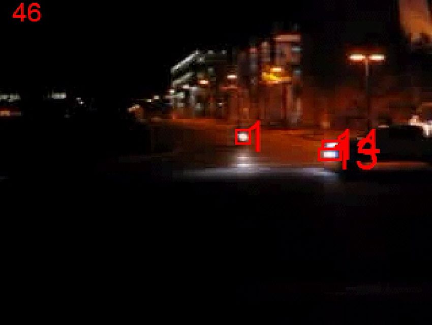
2.     Previous Work
   Motion segmentation is a common image processing
technique. Y. Liu et al. [1] presents a similar algorithm in
segmenting automobiles from the background. This
algorithm utilizes HSV colorspace mapping. We found
using the blue yellow channel in the opponent colorspace
proved more reliable than HSV for daytime illumination
conditions. V. Bhuvaneshwar et al. [2] also utilizes a
similar background subtraction for pedestrian detection.                                (a)
   The other field of tracking involves tracking by feature
points. The KLT tracker [4] is an example of this method.
   Our main goal was to utilize tracking solely for
incoming traffic detection therefore a simple tracking
based on motion segmentation and connected component
labeling would be suitable.

3.     Approach

3.1.    Motion Segmentation
   The motion segmentation algorithm applied is a                                       (b)
variant of the common image subtraction technique.
Image subtraction is often used to recover motion from a
video footage. The background image is defined as all the
static objects in the footage while the result of the image
subtraction will give all the moving objects in the
foreground. Defining the background image is the
variation.
   Many projects define the background image to be the
previous frame or a set empty frame. We define the
background image to be a sliding temporal average
window of the previous n frames. In our case, we set n to
15 frames. A sliding temporal average window proved to                                  (c)
be most effective definition of the background image.
Using just the previous frame gave low subtraction values      Figure 2. (a) Original video frame. (b) Image
when the motorbike was traveling at a slow rate.                    subtraction using RGB. (c) Image
Additionally, using a set empty frame is possible but very     subtraction using the blue/yellow channel of
susceptible to difficulties with camera vibrations or                     Opponent colorspace.
changing conditions.
   We used a dual algorithm for the image subtraction by       L*A*B* colorspace. The highly non-linear definitions of
selecting the colorspace. In late evening and nighttime,       L*A*B* proved to be ineffective with low resolution
we used RGB subtraction. The headlights of motorbikes          imaging. We had also tested the HSV colorspace. We
are defined cleanly against a dark background. In              applied image subtraction on each component separately.
daytime, the lighting conditions are illuminated and           The result was a noisy image. If we solely use the value
motorbikes are difficult to distinguish from the               (or intensity) component, the motorbike was present but it
background using RGB. We used only the blue/yellow             was also sensitive to noise creation.
channel in the opponent colorspace for daytime image               We used opponent colors in hopes that the nonlinear
subtraction. We discarded the luminance and red/green          definitions (compared to L*A*B*) would give better
channel.                                                       results on low resolution video. Using just the blue/yellow
   RGB colorspace for image subtraction on daytime             channel proved to be most effective and we elected to use
footage proved very ineffective at segmenting the motion       it for high illumination scenes.
of an incoming motorbike. Our first alternative was the
The selection algorithm computes the average RGB
pixel value in the current frame and if below a certain                 To limit the number of similar lines produced, we
threshold (we used 100), the image would be considered               limited the computation to three decimal points. In Fig.
low luminance (night time) and we select RGB                         3, a motorcycle merged with an opposing car’s path
colorspace. Otherwise, we select the opponent colorspace             and the motion tracking mis-tracked the objects.
for processing high luminance footage.                               RANSAC allows robust trajectory estimation by a
                                                                     partial line fitting even in the presence of wrongly
3.2.    Tracking                                                     tracked objects. With the RANSAC algorithm, we can
                                                                     still estimate the motorcycle’s path for classification as
3.2.1    Connected Component Labeling                                incoming traffic.
   A binary threshold is applied to reduce noise and allow
a connected component labeling. 8-connectivity is used as
the parameter for the labeling algorithm. We compute the
centroid, area and bounding box of each labeled object in
the frame.

3.2.2    Motion Tracking

   In the first frame of the captured footage, we store all
the labeled objects into a global data structure. In all
succeeding frames, we subtract each object’s centroid
from every object in the global data structure. We
consider the minimum distance object as a possible match
for the current object. If the object is below a threshold               Figure 3. RANSAC is utilized to create
distance difference and area difference, we assume it is                robust trajectory estimations from data
the same object. We add the current object’s centroid                                   points.
location to the position list of the matched object in the
global data structure. If there were no objects in the global
data structure that were within the threshold distance and      4.     Experimental Results
area difference, we add the current object to the global           We setup our fixed camera next to an intersection to
data structure.                                                 capture video footage. The resolution was set at 320x240,
                                                                15 frames/sec. We selected a lower resolution to better
3.2.3    RANSAC Partial Line Fitting                            simulate the application with real-world low cost
                                                                cameras. The camera was approximately five feet off the
   To aid in trajectory creation, we utilize RANSAC [3] to      ground and facing incoming traffic. Due to restrictions of
create line models from each object’s position list.            this particular location, we were unable to position the
   RANSAC is used in the following manner:                      camera higher. A higher position mount would help
        1. Select two points from an object’s position list.    reduce occlusion.
        2. Create a line model from these two points.              Tests were conducted in day, evening and night
            (i.e. C1X + C2Y + C3 = 0)                           conditions with a motorbike alone and mixed with traffic.
        3. Compute y-values from the x-position list            The footage was spliced into short clips for ease of
            using the new line model.                           testing.
        4. Compute the distance of the estimated y-                As seen in Fig. 4a and 5, the proposed algorithm is
            values with the real y values from the position     able to segment the motorbike from background in both
            list.                                               daytime and nighttime when the motorbike is arriving in
        5. If the distance is within an error threshold,        the incoming traffic lane alone.
            add it to the list of inliers.
        6. If the list of inliers is greater than a set count
                                                                5.     Conclusion
            threshold, consider it as a possible trajectory
            path for the given object.                                These preliminary results show that creating a traffic
        7. Repeat this procedure for every two points in        light triggering sensor based on computer image
            the object list.                                    processing is very much a possibility. Further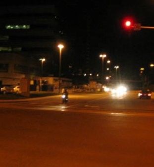
development on this project would include creating a
classification system based on the trajectory estimation
given by this algorithm. Additionally, motion tracking
could perhaps be improved by using a more advanced
tracking method such as the KLT tracker. [4]

           References
[1] Liu, Y. and Payeur, P. Vision-based detection of activity
    for traffic control. In IEEE CCECE 2003.
[2] V. Bhuvaneshwar and P. Mirchandani. Real-Time
    Detection Of Crossing Pedestrians For Traffic-Adaptive
    Signal Control. In IEEE Conf on Intelligent Transportation
    Systems, pages: 309-313, 2004.
[3] M. A. Fischler, R. C. Bolles. Random Sample Consensus:
    A Paradigm for Model Fitting with Applications to Image
    Analysis and Automated Cartography. Comm. of the ACM,
    Vol 24, pp 381-395, 1981.
[4] J. Shi, C. Tomasi. Good Features To Track. In IEEE
    CVPR, June 1994.
[5] M. Betke, E. Haritaoglu, and L. Davis. Highway scene
    analysis in hard real time. In IEEE Conf on Intelligent
    Transportation           Systems,     Boston,       1997.
    http://citeseer.ist.psu.edu/betke97high
    way.html.
[6] Maurin,       B.       Masoud,    O.     Papanikolopoulos,
    N.P. Tracking all traffic: computer vision algorithms for
    monitoring vehicles, individuals, and crowds. In Robotics
    & Automation Magazine, IEEE, 12(1): 29-36, 2005.
(a)
(b)
Figure 4. (a) At night time, incoming traffic objects are more easily tracked. (b) Plots of position
against frames. Object 1 is the motorbike’s headlight. Object 4 and 24 are fast moving cross-
traffic objects that are short-lived.
(a) (b)
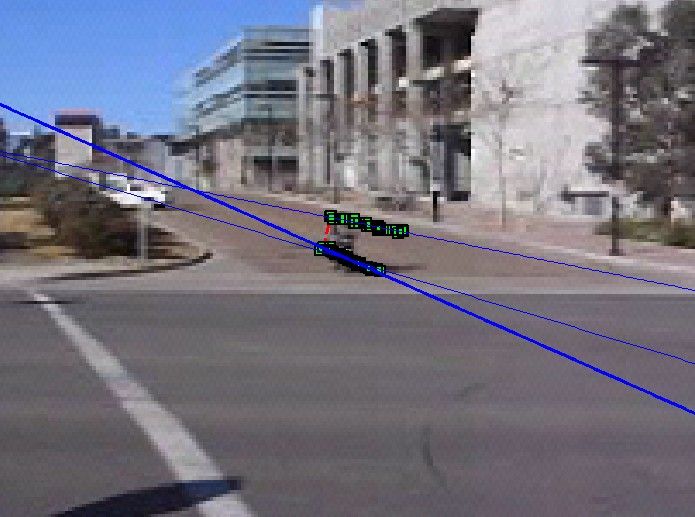
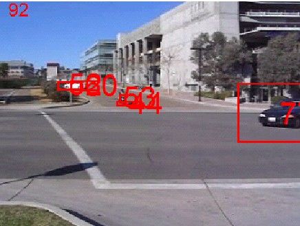
Figure 5. (a) Daytime footage zoomed out. (b) The same frame zoomed in. In day time, objects are
short lived compared to night time footage but the motorbike is detected.You can also read