Volume 10, Issue 3, March 2021 - IJIRSET
←
→
Page content transcription
If your browser does not render page correctly, please read the page content below

Volume 10, Issue 3, March 2021
International Journal of Innovative Research in Science, Engineering and Technology (IJIRSET)

                         | e-ISSN: 2319-8753, p-ISSN: 2320-6710| www.ijirset.com | Impact Factor: 7.512|

                                        || Volume 10, Issue 3, March 2021 ||

                                      DOI:10.15680/IJIRSET.2021.1003100

      Experimental Analysis of Swept Wing at
      Variable Angle Along with Tail Section of
            Fighter Aircraft.(BELL X5)
           Nikita Shukla1 ,S umeet Jangid2 ,Dinesh Janaparapu3 , Mohit Jogi 4 ,Rishit Rathod5
        Assistant Professor, Department Aeronautical Engineering, Parul University, Vadodara, Gujarat, India 1
           UG Student, Department of Aeronautical Engineering, Parul University, Vadodara, Gujarat, India 2
           UG Student, Department of Aeronautical Engineering, Parul University, Vadodara, Gujarat, India 3
           UG Student, Department of Aeronautical Engineering, Parul University, Vadodara, Gujarat, India 4
           UG Student, Department of Aeronautical Engineering, Parul University, Vadodara, Gujarat, India 5

ABSTRACT:W ing is major co mponent of aircraft. The wings are aerofo ils attached to each side of the fuselage and
are the main lift ing surfaces that support the airp lane in flight. The principal structural parts of the wing are spars, ribs,
and stringers. These are reinforced by trusses, I-beams, tubing, or other devices, including the skin and it’s have several
parts over it aileron, flap, slat and slot, etc. and sometime its act fuels tank and carrying engine too. In this project we
are doing analysis on BELL X5 aircrafts sweep wing with changing its angle. A variable-sweep wing, also known as a
"swing wing". A variab le-sweep wing work its function in order it’s allow the p ilot to use the optimu m sweep angle for
the aircraft's current speed, slow or fast. Here “swept wing" is normally used to mean "swept back”. The Bell X-5 was
the first aircraft capable of changing the sweep of its wings in flight.

KEYWORDS: Wing and tail Design, Mechanism of swept wing, CFD analysis etc.

                                                     I.   INTRODUCTION

   The idea o f making aircraft is co me out fro m the birds how they can flap their wings and fly in the air which results
in construction of flapping wing mechanis m of aircraft in the first era. They noticed that birds have aerofoil shape and
their body shave is very beneficial for small UA Vs. The most important and focused subject in av iation that how birds
can change their shape while flying and also stable in the sky. This study applied in sweep back wing in aircraft to
making them more efficient and more stable in air. Sweep back wing is defined as a changing the wings at desired
angles while flying to increase their performance in flight in any types of condition.

Two of the main characteristics of sweep back wing is wing angle and wing span. On an aircraft are wing sweep an d
wing span. For changing in span can, increasing aspect ratio increases lift -to-drag ratio, and decreases engine
requirements. Decreasing aspect ratio increases the velocity and decreases drag. By sweep change of aircraft can results
in increase in velocity and decrease the drag and however in decreasing the sweep can results in high lift coefficient.
Examples of sweep Back wing are P-1101, Bell X-5, XF101F-1 Jaguar, and F-111 Aardvark.

The Bell x5 was firstly built in between 1838-1939 and they having serials numbers of 50-1838 and 50-1839.The first
aircraft made its first flight on 15 February 1951 and second one made its first flying on 20 June 1951.By Bell x5 there
are appro ximately 200 flight records with the maximu m speed of 0.9 Mach and the highest altitude was achieved id
40000ft.First Aircraft we lost on 14 October 1953 as it’s failed to recover fro m the spine at 600 sweepback
wing.Although the testing of bell x5 has been continued till 1955 and it was in service un til late 1958 as a chase plane.

A variable-sweep wing, colloquially known as a "swing wing", is an airplane wing, or set of wings, that may be swept
back and then returned to its original straight position during flight. It allows the aircraft's shape to be modified in flig ht,
and is therefore an example of a variable-geometry aircraft.

IJIRS ET©2021                                    |   An IS O 9001:2008 Certified Journal |                                2058
International Journal of Innovative Research in Science, Engineering and Technology (IJIRSET)

                        | e-ISSN: 2319-8753, p-ISSN: 2320-6710| www.ijirset.com | Impact Factor: 7.512|

                                      || Volume 10, Issue 3, March 2021 ||

                                     DOI:10.15680/IJIRSET.2021.1003100

                                                       Fig. 1. 3D Model

                                                    II. METHODOLOGY

   The process of the entire pro ject is co mposed in three phases: (i) Modification of variable swept Wing and
Empennage, (ii) Calculation of changed parameters & analysis of the variable swept Wing and Empennage, (iii) Make
a Prototype model o f the aircraft. We will calculate the parameters like Pressure, Lift, Drag, and Coefficient of pressure
which applying on the Model by analyse it in the ANSYS. Then fro m the gain of the n ew values of the parameters we
will make a scaled Prototype model of the aircraft.

                                                          20 o Wing
                        Span                                    124cm
                        Root Chord                              30cm
                        Tip Chord                               15cm
                                                          40 o Wing
                        Span                                    98.2cm
                        Root Chord                              30cm
                        Tip Chord                               15cm
                                                          60 o Wing
                        Span                                    69cm
                        Root Chord                              30cm
                        Tip Chord                               15cm

                                                   Fig. 2. Wing Configurations

IJIRS ET©2021                                  |     An IS O 9001:2008 Certified Journal |                           2059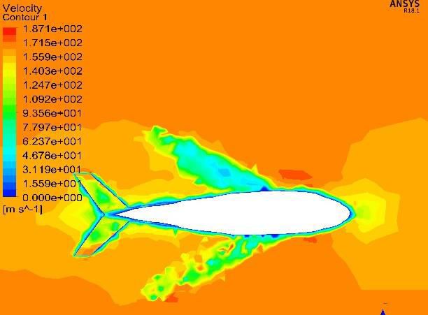
International Journal of Innovative Research in Science, Engineering and Technology (IJIRSET)

                         | e-ISSN: 2319-8753, p-ISSN: 2320-6710| www.ijirset.com | Impact Factor: 7.512|

                                       || Volume 10, Issue 3, March 2021 ||

                                     DOI:10.15680/IJIRSET.2021.1003100

                                              III. AEROFOIL      SELECTION

                                        Fig. 3. NACA 64A-10 aerofoil Mesh Domain

The selection of the aerofoil is the most crit ical part to design a variable angle wing geometry aircraft. The aerofo il
must meet the aerodynamic parameters such as coefficient of lift, drag; coefficient of mo ment etc. Whether it is
possible to have different aerofoils for the moving wing can be only after one understands the different structural needs.

In this study an aerofoil NACA 64A-10 is chosen. The shape/contours of the aerofoil are given in the lift characteristic
along with mo ment curve. We select this aerofoil is that generally the concept of variable swept wing is used in
aircrafts that tend to operate near the supersonic region therefore it is perfect to use an aerofoil that has a less thickness
and in this case 10% of the chord is used in NACA 64A-10.

                                                    Fig. 4. Graph of aerofoil

                                               IV. EXPERIMENTAL DATA

By performing CFD analysis in ANSYS 18.1 we found some configuration values of lift and drag on the surface of our
model. We conducted the experiment in three variable angles which are on 20 o , 40o , 60o . As a result of lift and drag
values of 20o 40o and 60o are shown as below.

IJIRS ET©2021                                   |   An IS O 9001:2008 Certified Journal |                               2060
International Journal of Innovative Research in Science, Engineering and Technology (IJIRSET)
| e-ISSN: 2319-8753, p-ISSN: 2320-6710| www.ijirset.com | Impact Factor: 7.512|
|| Volume 10, Issue 3, March 2021 ||
DOI:10.15680/IJIRSET.2021.1003100
Fig. 5. Lift graph of 20o swept Fig. 6. Drag graph of 20o swept
Fig. 7. Lift graph of 40o swept Fig. 8. Drag graph of 40o swept
Fig. 9. Lift graph of 60o swept
Fig. 10. Drag graph of 60o swept
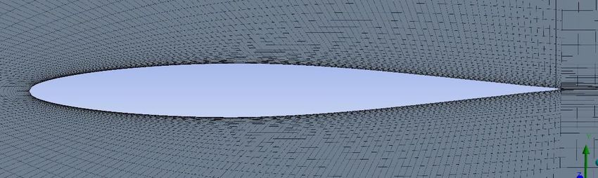
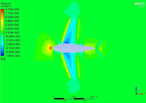
By performing CFD analysis in ANSYS 18.1 we found some configuration values of pressure contour and velocity
contour on the surface of our model. We conducted the CFD analysis in three variab le angles wh ich are on 20 o , 40o , 60o .
As a result of pressure contour and velocity contour values of 20 o 40o and 60o are shown as below.
IJIRS ET©2021 | An IS O 9001:2008 Certified Journal | 2061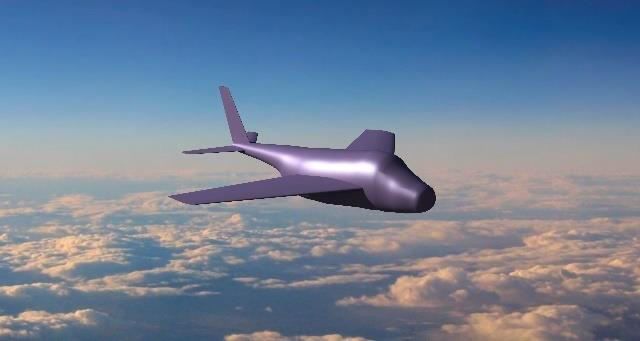
International Journal of Innovative Research in Science, Engineering and Technology (IJIRSET)

                       | e-ISSN: 2319-8753, p-ISSN: 2320-6710| www.ijirset.com | Impact Factor: 7.512|

                                    || Volume 10, Issue 3, March 2021 ||

                                  DOI:10.15680/IJIRSET.2021.1003100

  Fig. 11.Pressure contour of 20o swept                                Fig.12. Velocity contour of 20o swept

  Fig. 13.Pressure contour of 40o swept                                        Fig. 14. Velocity contour of 40o swept

    Fig. 15.Pressure contour of 60o swept                                       Fig. 16.Velocity contour of 60o swept

IJIRS ET©2021                               |   An IS O 9001:2008 Certified Journal |                           2062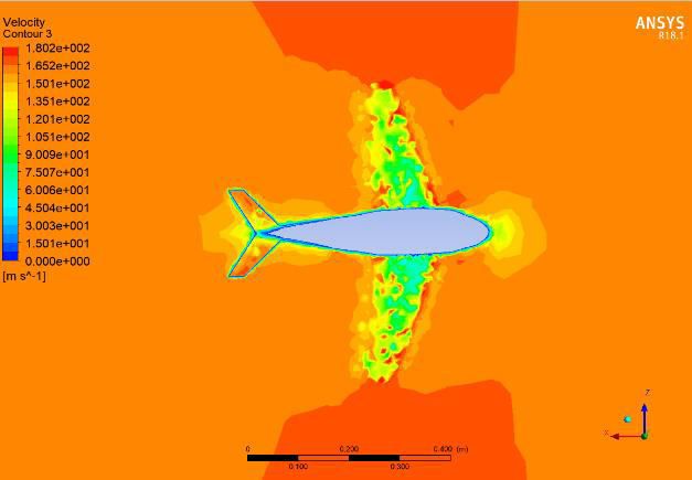
International Journal of Innovative Research in Science, Engineering and Technology (IJIRSET)

                        | e-ISSN: 2319-8753, p-ISSN: 2320-6710| www.ijirset.com | Impact Factor: 7.512|

                                      || Volume 10, Issue 3, March 2021 ||

                                    DOI:10.15680/IJIRSET.2021.1003100

                 Sr.    Swept angle         Pressure(N)           Lift(N)              Drag(N)
                 no.

                 1      200                 24.61                 3.54                 17.75

                 2      400                 24.9073               23.28                15.64

                 3      600                 18.2726               24.43                23.27

                                                    V. CONCLUSION

In the project "experimental analysis of swept wing at variable angle along with the tell section of fighter aircraft bell
x5" we learn about the sweep back wing how it's changes the angles of wings in during hanger time take-off time
gliding t ime and landing t ime we calculate all the dimensions and measurement to apply it on real steady model we
make steady model of bell x5 and analysis it on ANSYS 18.1 then after we concluded that the drag and lift of aircraft
and variable angle are d ifferent fro m each other as in results we got drag 17.75N and lift 3.54N in 20° sweep wing then
15.64N d rag and 23.28N lift in 40° sweep wing and in last 23.27N drag and 24.43N lift in 60° sweep wing. And it
finally conclude that changing angle in sweep wing is can be dangerous for any aircraft as it is in the air because of the
drag rises as the angle reduces and increases more than designed parameter.

                                                      REFERENCES

1.  CATIA V5 SOFT WARE (CATIA®)
2.  ANSYS 18.1
3.  https://scholar.google.com/scholar?hl=en&as_sdt=0%2C5&q=A+Transonic+Wind -
    Tunnel+Investigation+of+the+Longitudinal+Stability+and+Control+Characteristics+of+a+0.09 -
    Scale+Model+of+the+Bell+X-5+Research+Airp lane+and+Co mparison+With+Flight&btnG=
4. https://arc.aiaa.org/doi/abs/10.2514/6.2004-734
5. https://arc.aiaa.org/doi/abs/10.2514/6.2001-271
6. https://www.emerald.com/insight/content/doi/10.1108/eb034081/full/html
7. https://arc.aiaa.org/doi/abs/10.2514/3.45023?journalCode=ja
8. https://www.nasa.gov/centers/armstrong/news/FactSheets/FS-081-DFRC.html
9. https://en.wikipedia.org/wiki/Bell_X-5
10. https://www.nationalmuseum.af.mil/ Visit/Museum-Exhibits/Fact-Sheets/Display/Article/195758/bell-x-5/
11. Aircraft Design - A Conceptual Approach 2nd ed. - D. Raymer (1992) WW

IJIRS ET©2021                                  |    An IS O 9001:2008 Certified Journal |                           2063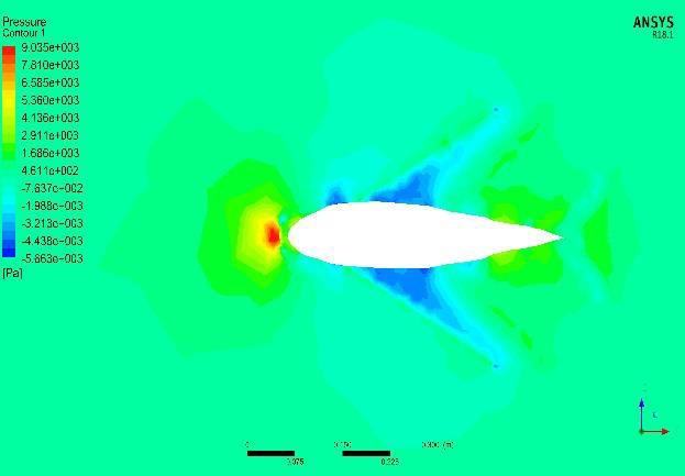
You can also read