Propagation of a Crack in a Composite Plate - revista de materiale ...
←
→
Page content transcription
If your browser does not render page correctly, please read the page content below
Propagation of a Crack in a Composite Plate

       IONEL IACOB *, IONEL CHIRICA , ELENA FELICIA BEZNEA
       Dunarea de Jos University of Galati, Faculty of Engineering, 47 Domneasca Str., 800008, Galati, Romania

       In this paper, a model of a composite plate with a central elliptical cut-out and with an initial fissure was
       subjected to a tension load in the finite element method (FEM) software Abaqus to observe the propagation
       of that crack during a certain amount of time that elapsed in the FEM analysis. Due to symmetry, only half of
       the plate was modeled, as a shell, and the extended finite element method (XFEM) was used for the
       crack. The material properties that were assigned to the plate were taken from the database of the Ansys
       Mechanical software. In the vicinity of the crack a finer mesh was applied to be able to better observe the
       evolution of the fissure and the changes of the Von Misses stress graphs for each time step of the analysis.
       Keywords: Crack Propagation, Abaqus, XFEM, Composite Plate

   For designing and fabricating a strong, resistant
composite material, that doesn’t break very easily, an
important factor that is necessary to be analyzed is how
cracks form and propagate in different combinations of
materials, based on their purpose. The propagation of the
cracks can be influenced by some fabrication flaws, for
example there can be flaws related to the fibers, matrix
porosity, interfacial porosity, etc. The existence of these
flaws can reduce the durability of the material, the cracks
propagating faster and easier [1].
   Because cracks are one of the possible defects that can
appear in composite materials, there is an interest in
simulating the propagation of these cracks, to be able to
                                                                         Fig. 1. The geometry of the plate with a central elliptical cut-out
predict the initiation of a crack, in which direction it will
                                                                                        and a crack (dimensions in mm)
propagate, how much time it takes until a structure made
from a certain composite breaks due to cracking, etc. [2].
   There have been multiple studies that have analyzed
different aspects of crack propagation, under different types
of loading cases.
   Some researchers [3-5] studied the fracture behavior of
composites under static loading conditions, this being a
simplification of what happens in reality, when there are
more complex, dynamic loading cases [2].
   There are also numerous studies on the behavior of
cracks in composite materials subjected to dynamic
loadings [6- 8] and fatigue loading cases [9, 10].
   In 1999, Ted Belytschko created the extended finite                                                       Fig. 3. The mesh used for the
element method (XFEM) [11]. Multiple crack propagation                                                                  analysis
studies [2, 12, 13] have used this method, since then, for             Fig. 2. The boundary conditions
some of its advantages when it comes to meshing models                    and the tension pressures
with fractures. In the last decade the various meshing                  applied to the analyzed model
methods have been used for the modelling of multilayered                  -the translation on the x axis and the rotation around the
polymeric composites, like in [14, 15], where so static and            z axis were blocked on the contour of the model
dynamic analysis is studied.                                              -symmetry conditions for the other half of the plate
                                                                          On the top and bottom contour lines of the shell model
Experimental part                                                      tension pressures of 100 - 500 MPa were applied.
Model description                                                         A quadrilateral mesh was used (fig. 3), with an
   In this paper an epoxy-glass composite plate with a                 approximate global size of 100 millimeters. Around the
central cut-out was analyzed using the Abaqus software.                crack and also on the right contour line, more elements
The dimensions of the plate (fig. 1) were 3000 mm length,              were applied. This was done so that the difference in size
2000 mm width and the central elliptical cut-out had 1500              of the elements wasn’t very big in the vicinity of the crack
mm total length with a radius of 500 mm at each end. An                and to improve the accuracy of the results.
initial crack of 150 mm was also modeled for the extended
finite element method. Only half of the plate was                      Results and discussions
modeled, with symmetry conditions.                                     FEM analysis
   The following boundary conditions have been applied                   After the maximum number of increments (1000) and
to the model (fig. 2):                                                 the increment size (initial 0.02; minimum 1e-007;
                                                                       maximum 1) have been set, a static analysis was run. The
* email: ionel.iacob@ugal.ro
MATERIALE PLASTICE ♦ 55♦ No. 2 ♦ 2018              http://www.revmaterialeplastice.ro                                                     179
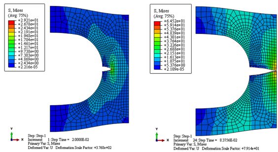
Fig. 5. The Von Misses stresses [MPa] for
        Fig. 4. The Von Misses stresses [MPa] for      the increment of the analysis when the plate
       the first increment of the analysis for an          model breaks, for an applied tension
         applied tension pressure of 100 MPa                        pressure of 100 MPa

      Fig 6. The displacement values [mm] for the           Fig. 7. The displacement values [mm] for the
      first increment of the analysis for an applied          increment of the analysis when the plate
                tension pressure of 100 MPa                     model breaks, for an applied tension
                                                                         pressure of 100 MPa

                                                       Fig. 9. The Von Misses stresses [MPa] for
      Fig. 8.The Von Misses stresses [MPa] for
                                                        the increment of the analysis when the
      the first increment of the analysis for an
                                                           plate model breaks, for an applied
        applied tension pressure of 500 MPa
                                                               tension pressure of 500 MPa

180                               http://www.revmaterialeplastice.ro         MATERIALE PLASTICE ♦ 55♦ No. 2 ♦2018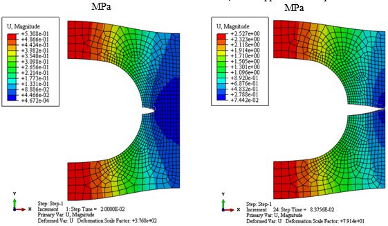
Fig. 11. The
                                                                                                             displacement values
                                                                                                           [mm] for the increment
  Fig. 10. The displacement                                                                                of the analysis when the
   values [mm] for the first                                                                               plate model breaks, for
increment of the analysis for                                                                                 an applied tension
 an applied tension pressure                                                                                 pressure of 500 MPa
           of 500 MPa

                                                                                                                     Table 1
                                                                                                                 THE VON MISSES
                                                                                                                  STRESSES FOR
                                                                                                                  THE ANALYZED
                                                                                                                 PRESSURE CASES

                                                                      results that were observed were, mainly, the effects that
                                                                      the propagation of the crack had on the Von Misses stresses
                                                                      and the displacements of the plate, until the breaking
                                                                      moment occurs. In the following figures, the starting and
                                                                      the breaking increments for the 100 MPa pressure cases
                                                                      are presented. The rest of the results are presented in the
Fig. 12. The variation of the maximum Von Misses stress values in     tables 1, 2 and the diagrams 12, 13.
 time for the analyzed tension pressures cases that were applied

MATERIALE PLASTICE ♦ 55♦ No. 2 ♦ 2018             http://www.revmaterialeplastice.ro                                           181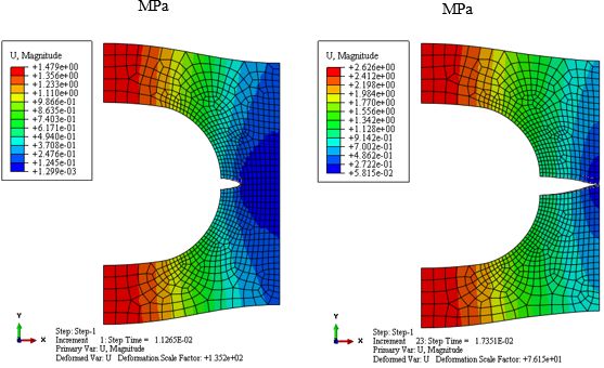
Table 2
                                                                                                                   THE DISPLACEMENT
                                                                                                                    VALUES FOR THE
                                                                                                                       ANALYZED
                                                                                                                    PRESSURE CASES

                                                                                         Fig. 13. The variation of the maximum
                                                                                          displacement values in time for the
                                                                                         analyzed tension pressures cases that
                                                                                                      were applied

                                                                    these stress variations continue until the plate breaks in
                                                                    two halves. After a certain point, when the crack
   The results obtained from Abaqus are gathered in the             approaches the breaking point, there are multiple rapid
tables 1 and 2 and the diagrams from figures 12 and 13.             stress increases and decreases, meaning that the fissure
                                                                    propagates faster. By observing the displacement values it
Conclusions                                                         can be seen that there is an almost linear increase until
   The analysis using the FEM software Abaqus of an epoxy-          near the breaking point, when there is a much faster
glass composite plate with a central elliptical cut-out and         increase.
an initial crack was presented in this paper. Only half of the         As it can be expected and also according to the results
plate was modeled, due to symmetry, with contour                    from Abaqus, the higher the applied tension pressure is,
constraints and five tension pressure cases were applied            the faster the fissure will propagate until the plate breaks.
to two of the plate’s edges. The main results that were                Some of the future research directions may include
observed were the variation of the Von Misses stress and            changing the composite materials used, replacing the
the evolution of the displacement values in a certain               constant pressures with fatigue loadings and comparisons
amount of time that was needed for the initial crack to             between software results and experimental results.
propagate until the break of the plate.
   By analyzing the tables and the graphs it can be observed        References
                                                                    1. BEAUMONT, P. W., HARRIS, B., The energy of crack propagation in
that the Von Misses stresses, for all pressure cases, have
                                                                    carbon fibre-reinforced resin systems. Journal of Materials Science,
an initial linear increase until the initial crack visibly opens
                                                                    7(11), 1265-1279
more than the length it had until then, due to the tension
                                                                    2. MOTAMEDI, D., MOHAMMADI, S., Fracture analysis of composites
pressures, then there is a decrease, until the crack starts
                                                                    by time independent moving-crack orthotropic XFEM. International
opening more, when another stress increase can be seen;
                                                                    Journal of Mechanical Sciences, 54(1), 20-37
182                                             http://www.revmaterialeplastice.ro       MATERIALE PLASTICE ♦ 55♦ No. 2 ♦2018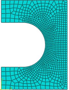
3. FIEDLER, B., HOJO, M., OCHIAI, S., SCHULTE, K., ANDO, M., Failure      10. DAUSKARDT, R. H., DALGLEISH, B. J., YAO, D., RITCHIE, R. O.,
behavior of an epoxy matrix under different kinds of static               BECHER, P. F., Cyclic fatigue-crack propagation in a silicon carbide
loading. Composites Science and Technology, 61(11), 1615-1624             whisker-reinforced alumina composite: role of load ratio. Journal of
4. LIU, S., NAIRN, J. A., The formation and propagation of matrix         materials science, 28(12), 3258-3266
microcracks in cross-ply laminates during static loading. Journal of      11. MOES, N., DOLBOW, J., BELYTSCHKO, T., A finite element method
reinforced plastics and composites, 11(2), 158-178                        for crack growth without remeshing. International Journal for
5.ZWEBEN, C., Tensile failure of fiber composites. AIAA                   Numerical Methods in Engineering. 46 (1), 131-150
journal, 6(12), 2325-2331                                                 12. YE, C., SHI, J., CHENG, G. J., An Extended Finite Element Method
6. THEOCARIS, P. S., MILIOS, J., Dynamic crack propagation in             (XFEM) study on the effect of reinforcing particles on the crack
composites. International Journal of Fracture, 16(1), 31-51               propagation behavior in a metal-matrix composite. International
7.WANG, B. L., HAN, J. C., DU, S. Y., Cracks problem for non-             Journal of Fatigue, 44, 151-156
homogeneous composite material subjected to dynamic                       13. HUYNH, D. B. P., BELYTSCHKO, T., The extended finite element
loading. International Journal of Solids and Structures, 37(9), 1251-     method for fracture in composite materials. International Journal for
1274                                                                      Numerical Methods in Engineering, 77(2), 214-239
8.MAMALIS, A . G., MANOL AKOS, D. E., IOANNIDIS, M. B.,                   14. ZGIRIAN, G., DEMETRESCU, I., GHEORGHIU, H., IOVU, H., HADAR,
PAPAPOSTOLOU, D. P., On the response of thin-walled CFRP                  A., ATANASIU, C., The modelling of some polymeric compounds:
composite tubular components subjected to static and dynamic axial        from synthesis to mechanical properties and finite elements
compressive loading: experimental. Composite structures, 69(4), 407-      calculation. Rev. Chim. (Bucharest), 56, no. 7, 2005, p. 757
420                                                                       15. CORMOS, R., PETRESCU, H., HADAR, A., ADIR, G.M., GHEORGHIU,
9. GASSAN, J., A study of fibre and interface parameters affecting the    H., Finite Element Analysis of the Multilayered Honeycomb Composite
fatigue behaviour of natural fibre composites. Composites part A:         Material Subjected to Impact Loading, Mat. Plast. 54, no. 1, 2018, p.
applied science and manufacturing, 33(3), 369-374                         180

                                                                          Manuscript received: 23.11.2017

MATERIALE PLASTICE ♦ 55♦ No. 2 ♦ 2018                 http://www.revmaterialeplastice.ro                                                   183
You can also read