Analysis of Puncture and Prediction of Crack Fatigue in Drilling Tools
←
→
Page content transcription
If your browser does not render page correctly, please read the page content below
E3S Web of Conferences , 03003 (2020) https://doi.org/10.1051/e3sconf/202019803003
ISCEG 2020
Analysis of Puncture and Prediction of Crack Fatigue in Drilling
Tools
Guangqiao Li1,*,Kejun Zhai2, and Zhongxi Zhu3,*
1Petroleum Engineering Technology Research Institute, Sinopec Northwest Oilfield Company, 830011 Urumqi, China
2Key Laboratory of Enhanced Recovery for Fracture-Cave Oil Reservoir, Sinopec, 830011 Urumqi, China
3Petroleum Engineering College, Yangtze University, 430100, Wuhan, Hubei, China
Abstract. In recent years, the drilling technology of directional wells and large displacement wells has
been widely used, which has greatly improved the reservoir development efficiency. However, the
“stabbing” accidents in the drilling of the inclined section drilled frequently occur frequently. In view of the
above problems, this paper uses the finite element method to take the well “003-H1”, which is more serious
in the drilling tool, as the research object, and deeply analyzes the cause of the “stabbing” of the drilling
tool and the prediction of the crack extension period. The results show that the “piercing” of the drill pipe is
mainly caused by the fatigue failure of the drill pipe. The crack on the surface of the drill pipe increases
with the slope of the construction. The crack changes rapidly from elastic expansion to plastic expansion,
and the fatigue life is “breaking” down, move down to create a slanting point position, which can reduce the
occurrence of drill pipe "stabbing" accident.
1 Introduction After about one month, the drill “stab leak” phenomenon
reappeared, and nine consecutive identical drill failures
Drilling "stabbing" accidents often occur in deep well occurred in 14 days.
drilling with shallow slopes. According to statistics, Throughout the failure characteristics of drilling tools,
since 2012, there have been many accidents such as there are three commonalities: first, the failure parts
frequent punctures and broken drills after a certain occur in the range of 400~600mm from the shoulder of
period of construction work due to shallow sloping the female joint, and the transition zone of the upset zone
points. These include Daqing Drilling South 3-15, China disappears; 7 of the 9 failures occur in the wellhead
National Offshore Oil Service Z6-9-A5, Z6-9-A8 wells, 300~600m side track near the dog leg; the last 9 failures
of which the “stab leak” phenomenon in the 003-H1 well occurred in the 215.9mm wellbore PDC drilling process,
is the most serious [1]. According to the literature [2] the maximum speed of 90r/min.
and local data, it can be seen that most of the wells with
the "stab leak" of the drilling tool are between 200 and
2.2 General Precautions
600m, and the maximum dogleg angle is 3o to 6o. The
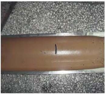
position of the "puncture" is roughly on the side. Drill According to the standard of GB/T 24956-2010
near the dog leg (Figure 1). "Recommended Practice of Drill String Design and
Operation Limit of Oil and Gas Industry", the slanting
2 Drilling Tool "Puncture" Example And point of the 003-H1 is 260m, the dogleg angle is 60, and
the depth of the well is 2128m. The inclined section of
General Precautions Well West 003-H1 is the fatigue damage zone.
Through GB/T 24956-2010 (Figure 3), the life
2.1 Failure Analysis of Drilling Tools In Well expectancy of the S135 drill pipe is 100%. Therefore, the
003-H1 drill pipe with a calculated service life of 100% should
be carefully inspected. If it is not downgraded or
In the design of the well body structure of the 003-H1 scrapped, it should be closely monitored as much as
well, shallow wells were used for shallow well drilling. possible [3].
The position of the inclined point was 260m, the inclined
section was 400~624m, and the wellbore was drilled to
2128m. 3 times of outer diameter of 127mm drill pipe 3 Finite Element Simulation and Post
thickening transition disappearance zone piercing failure, Processing
For the third time, the large-diameter drill pipe with steel
grade S135 and outer diameter of 127mm was replaced.
3.1 Analysis` of The Force of The Drill Pipe
*
Corresponding author: zhuzhongxi@126.com
© The Authors, published by EDP Sciences. This is an open access article distributed under the terms of the Creative Commons Attribution License 4.0
(http://creativecommons.org/licenses/by/4.0/).
E3S Web of Conferences , 03003 (2020)                                                       https://doi.org/10.1051/e3sconf/202019803003
ISCEG 2020

           Calculation of axial stress                                               N b =0.0785PDn 103
                                                                                                                              漏6漐
                                    F
                     z=                            10-6

                             4
                                 D   2
                                           d2
                                                             漏1漐
           Calculation of bending stress [4]

                                           L    F
                            E  D C
                     i =                  2    EI
                                      L     F
                              2th
                                      2     EI
                                                             漏2漐

                                                                        Fig 2 The limit of the dog's leg severity when the S135 steel
                                                                                    grade drill pipe is fatigue-damaged

                                                                            Fig 3 Fatigue damage diagram in a gradient dogleg

                                                                       Through GB/T 24956-2010 (Figure 3), the life
                                                                       expectancy of the S135 drill pipe is 100%. Therefore, the
                                                                       drill pipe with a calculated service life of 100% should
                                                                       be carefully inspected. If it is not downgraded or
                                                                       scrapped, it should be closely monitored as much as
                                                                       possible [3].

                                                                       3.2 Setting of Boundary Conditions
                                                                       The drill pipe is affected by axial stress, bending stress
                                                                       and torque at the shallow point. The axial and bending
                 Fig 1 Photo of the failed drill in Well 003-H1        stresses provide open-type cracks, and the torque
                                                                       provides tear and slip-type cracks. According to the
                                                                       fracture mechanics and the actual working conditions of
           Torque calculation [5]                                      the well site, it is shown that most of the drill pipe
                                                                       fractures are open-type cracks. Therefore, the range of
                      N  NS  Nb                                      the female joint thread shoulder is 400-600mm, and the
                                                             漏3漐       transition zone of the upset belt is the research object.
                                                                       The preset crack is perpendicular to the rod body, and
                            9549  N S +N b
                      M=                                               the most commonly used elliptical crack in fracture
                                   n                         漏4漐       mechanics is used as the model [6]. The drill rod is fixed
                                                                       at one end and the other end is subjected to tensile load
                     N s =4.6C m d c2 Ln 10-7                        and torque. With the well depth of 2128m, the slanting
                                                             漏5漐       point of 260m and the dogleg angle 70 as the boundary

                                                                   2
E3S Web of Conferences , 03003 (2020) https://doi.org/10.1051/e3sconf/202019803003
ISCEG 2020
conditions, the axial tensile force is calculated as
133.8Mpa and the bending stress is 16.5Mpa by the
formula 1~6. The torque is 7800N·m.
The elastic modulus of the drill pipe is 2.12×10 5Mpa
and the Poisson's ratio is 0.28. The true stress-plastic
strain relationship of the material can be checked by the
literature [7]. Figure 4 shows that a is the crack depth
(ellipse short semi-axis), c is the crack width (ellipse
long semi-axis), t is the drill pipe wall thickness, A is the
crack front edge point, B is the crack boundary point,
here is convenient for description The crack shape is
defined as γ by a/c, and the crack depth ratio a/t is
defined as τ.
Fig 5 Linear elastic (top) and elastoplastic (lower) crack
stress cloud
3.4 Finite Element Result Processing
Through the finite element software simulation, the
stress intensity factor of the crack leading edge
corresponding to different crack shape ratio γ and crack
depth ratio τ is calculated by the public description 8.
K f ac
漏7漐
Fig 4 Mechanical model of crack in the rod
3.3 Crack Finite Element Simulation
When the cracked mesh is divided, the crack propagates
to form an asymmetric structure due to the torque action.
Therefore, it is necessary to refine the near crack
segment mesh [8], where the maximum circumferential
radius of the crack leading edge encryption region is 0.5
mm, and the circumference is divided into 12 equal parts,
the encryption unit layer is 8 layers. The crack position
is a hexahedral mesh, and the rest is a tetrahedral mesh.
The finite element simulation is performed on the Fig 6 The solid line is the stress intensity factor at point A,
and the dotted line is the stress intensity factor at point B.
divided mesh, and a set of linear elastic and elastoplastic
As can be seen from Fig. 6, the same depth is equal
stress maps are obtained.
to the 煹 condition, and the stress intensity factor
Figure 5 shows that the linear elastic crack has a
relatively small stress change at the leading edge of the corresponding to the intersection of the solid line and the
crack, and the strain is relatively uniform at the leading broken line is the same, and the stress intensity factor of
edge. It is suitable for the drill pipe to work underground, each point of the crack leading edge of the crack is the
and the elastoplastic crack is uneven due to the uneven same at the combined load, that is, the diffusion rate of
distribution of the stress at the leading edge. The linear each point is the same. The shape ratio at this time is
distribution promotes the accelerated propagation of called the critical shape ratio [9]. The critical shape ratio
cracks. Experiments have shown that the “piercing” of at each depth ratio is recorded and further calculated by
the drill pipe is mainly due to the formation of finite element software.
elastoplastic cracks in the later stage of drilling.
Therefore, it is important to study the expansion mode of
elastic cracks and extend the fatigue cycle time of linear
elastic cracks, which will play an important role in
slowing the "piercing" of drill pipes.
3E3S Web of Conferences , 03003 (2020) https://doi.org/10.1051/e3sconf/202019803003
ISCEG 2020
(3) Before the drilling tool is placed under the
stratum, the crack near the transition zone of the drill
pipe upset zone should be inspected and graded in time.
If it is not a special case, when drilling in medium and
deep wells, the depth of the inclined point should be
moved as much as possible to reduce the occurrence of
“stabbing” accidents.
References
1. Zhu Guoning, Xu Di. Analysis of Causes of Failure
of Drilling Tools in Bohai Oilfield and
Countermeasures. Petro China Chemical Industry
Standards and Quality, 2018(10).
Fig 7 Effect of different τ on stress intensity factor of crack 2. Zhu Quanta, Yue Yuhua, Wang Dekang, et al.
front Relationship between shallow point and fatigue
The solid line is the elastoplastic stress intensity cumulative failure of drilling tools and its
factor and the dashed line is the linear elastic stress enlightenment.Natural Gas Industry, 2014, 34(9):
intensity factor. 76-83.
The solid line in Fig. 7 shows the stress intensity
3. General Administration of Quality Supervision,
factor at the crack leading edge under elastoplastic
Inspection and Quarantine, China National
conditions, and the broken line indicates the stress
Standardization Administration, GB/T 24956-2010.
intensity factor under the linear elastic condition. By
Oil and gas industry Recommended practice for drill
studying the stress intensity corresponding to the 90o
string design and operating limits. Beijing: China
angle elasticity and plasticity, it can be obtained as the
Standard Press, 2010
crack depth increases, at point A. The difference in stress
intensity factor continues to rise. When 煹 is greater than 4. Fang Zhou. Failure Analysis of Drill Pipe.
0.6, the plastic component exceeds 10% (Figure 8). At Southwest Petroleum University, 2006.
this moment, the elastoplastic constitutive relationship is 5. Shi Xiaobing, Shi Taihe. Study on failure of drill
more suitable. string in the lower part of curved wellbore.Journal
of Southwest Petroleum University(Natural
Science),2001, 23(5):54-57.
6. Zhao Guanghui, Zhao Li, Shi Jian, et al. Fracture
properties of surface cracks in drill pipe joints.
Chinese Journal of Applied Mechanics, 2016, 33(5):
838-844.
7. Shi Yiping, Zhou Yurong. Detailed Explanation of
ABAQUS Finite Element Analysis. Mechanical
Industry Press, 2006.
8. Zhao Guanghui, Zhao Li, Tang Song, et al. Fracture
properties of surface cracks in thickened transition
section of drill pipe.Journal of Mechanical Strength,
Fig 8 Effect of τ on the percentage of crack diffusion rate 2017(04):177-183.
9. Wang Haozhen. Study on static and dynamic
fracture characteristics of three-dimensional cracks
4 Conclusion on the surface of drill string. Southwest Petroleum
University, 2014.
(1) Drill pipe with fatigue loss level up to 100%, the
critical shape ratio of cracks in the inclined section can
be calculated by finite element software, and the crack
propagation period is calculated by Ncode software. The
drill pipe is taken out in advance after the crack
propagation reaches the high speed zone. Prevent the
occurrence of "punctures".
(2) Taking the 003-H1 well as an example, the crack
growth rate of the drill pipe in the vertical section is slow
and the service life is long. When the drill pipe reaches
the inclined section, the drill pipe is rapidly transformed
into a plastic crack by the elastic crack. The fatigue cycle
is “falling off”, so it is important to calculate the fatigue
cycle of the drill pipe at the bevel.
4You can also read