Volume 10, Issue 6, June 2021 - Ijirset.com
←
→
Page content transcription
If your browser does not render page correctly, please read the page content below

Volume 10, Issue 6, June 2021
International Journal of Innovative Research in Science, Engineering and Technology (IJIRSET)

                      | e-ISSN: 2319-8753, p-ISSN: 2320-6710| www.ijirset.com | Impact Factor: 7.512|

                                      || Volume 10, Issue 6, June 2021 ||

                                   |DOI:10.15680/IJIRSET.2021.1006169|

    Future Scope for Automation in Centerless
                     Grinder
        Prof: Dinesh Parwe, Mr. Pranay Ukunde , Mr. Amol Singh Gour, Mr. Rajesh Thakur ,
                                              Mr. Sharique Shaeikh
   Department of Mechanical Engineering, Govindrao Wanjari College Engineering and Technology, Nagpur, India

ABSTRACT : This paper report are design of autoloader center less grinding To reduce the man power during the
total process of Top Link Crank Shaft. To reduce the Muri. Due to manual loading process production is depend on
operator. , Delay for loading job or excess pressure applied on job during Grinding, Incomplete grinding, Chances of
accident , Extra load on centre less grinding machine (Grinding Wheel, Control Wheel & Carbide Plate).

                                                  I. INTRODUCTION

Centre less grinding is widely used in industry for precision machining of cylindrical components because of its high
production rate, easy automation, and high accuracy. 20X -carbon infiltration steel is a common alloy steel that is
usually used in mechanical engineering using centerless grinding process Center less grinding is a process for
continuously grinding cylindrical surfaces in which the work piece is supported not by centers or chucks but by a rest
blade. The work piece is ground between two wheels. The larger grinding wheel does grinding, while the smaller
regulating wheel, which is tilted at an angle, regulates the velocity of the axial movement of the work- piece. Center
less grinding can also be external or internal, traverse feed or plunge grinding. The most common type of center less
grinding is the external traverse feed grinding
Objectives:- Replacement of One operator by Auto loading System ,Total operator for the process 7 no’s reduced by 6
nos. ,Quantity of production improved by 200 no’s per day, Quality improved due to equal pressure during grinding
operation., Chances of accident avoid ,No Extra load on centre less grinding machine(Grinding Wheel, Control Wheel
& Carbide Plate) Life of carbide plate improved.

                                                  II. A REVIEW ON

T.John Institute of Tchnology,Bangalore-83 2Gogte Institute of Technology, Belgaum 3Rachana InfoTech Pvt Ltd,
Belgaum
Dr.M.S.Patil2 Satish Homkar3 Swetadri Srinivasan
During operation there is chance of overlapping of rods that damages the grinding wheel or stops the operation, for that
purpose pneumatic proximity sensor is attached. Output of sensor placed nearer to the grinding machine, input attached
to the cylinder. Mainly pneumatic proximity sensors involve the use of compressed air, displacement or the proximity
of an object being transformed into a change in air pressure. Low pressure air is allowed to escape through a port in
front of the sensor. This escaping air, in the absence of any close-by object, escapes and in doing so also reduces the
pressure in the nearby sensor output port. However, if there is close-by object, the air cannot so readily escape and
result is that the pressure increase in the sensor output port. The output pressure from the sensor thus depends on the
proximity of objects. Here, in this case inductive proximity sensor is used. It can be used for the detection of metal
objects and is best with ferrous metals
Thermal variation in machine tools greatly affects the dimensional tolerances of work pieces and causes various defects
in manufacturing process. For preventing thermal distortion that makes to substantial improvement in quality,
manufacturing efficiency and energy saving

IJIRSET © 2021                                |   An ISO 9001:2008 Certified Journal |                            6914
International Journal of Innovative Research in Science, Engineering and Technology (IJIRSET)
| e-ISSN: 2319-8753, p-ISSN: 2320-6710| www.ijirset.com | Impact Factor: 7.512|
|| Volume 10, Issue 6, June 2021 ||
|DOI:10.15680/IJIRSET.2021.1006169|
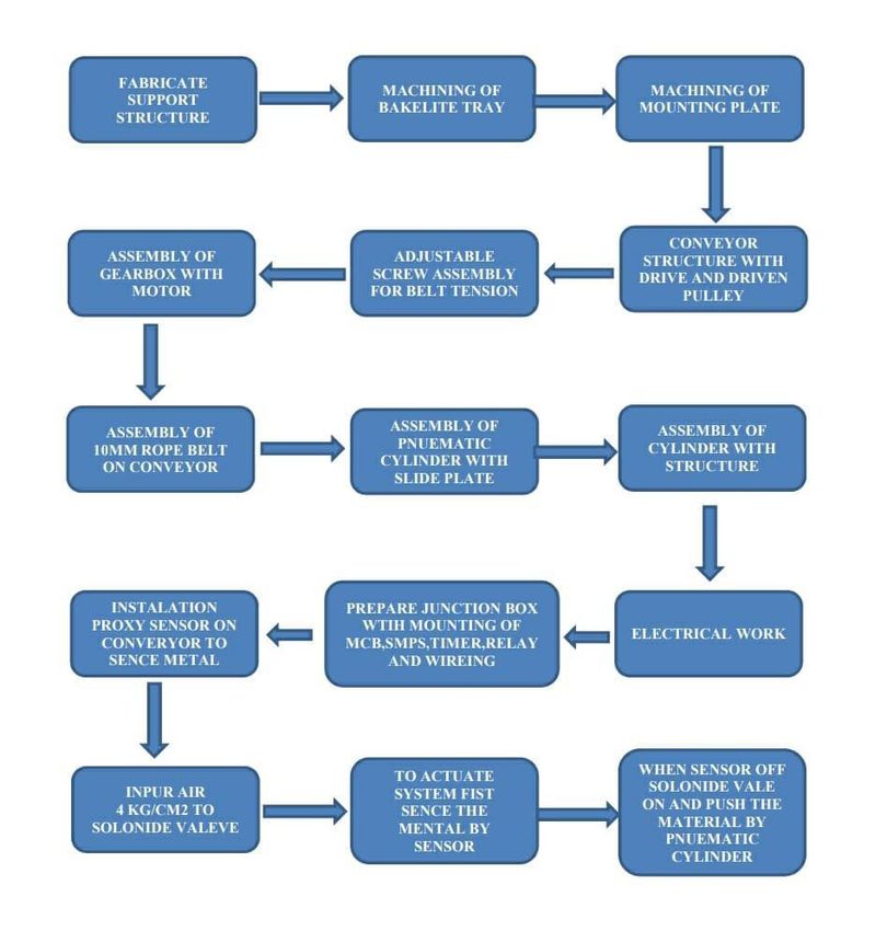
III. METHODOLOGY
Fig no: 1 Methodology
IV. PLANNING AND PROCESS
List of components used in auto loading assembly:-
Fabricated structure:-
Backlit sheet this is used to avoid marking on grinding surface. The bulk quantity of material loaded in a tray in that
case material slide on surface of tray it makes because marking on grinding material. to avoid a friction between two
metal surface we are using backlit sheet it is hard machine able light in weight .
Conveyor structure is used to tray to center less grinder , conveyor rope used to carry the material and slide after
overloading , conveyor drive Gear box & Motor used to 0.25 HP motor with warm gear box of output 10 RPM,
Pneumatic Cylinder with 5” Stroke used to lift the material from tray and transfer it to conveyor , solenoid valve is used
to actuated by séance for movement of the cylinder up and down , proxy sensor used séance the material and actuated
solenoid valve , SMPS convertor is used to AC power to DC power to input supply of solenoid valve , sensor ,timer ,
relay, MCB used to isolated,
IJIRSET © 2021 | An ISO 9001:2008 Certified Journal | 6915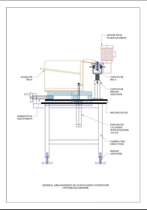
International Journal of Innovative Research in Science, Engineering and Technology (IJIRSET)

                      | e-ISSN: 2319-8753, p-ISSN: 2320-6710| www.ijirset.com | Impact Factor: 7.512|

                                       || Volume 10, Issue 6, June 2021 ||

                                    |DOI:10.15680/IJIRSET.2021.1006169|

                      V. EXPERIMENTAL SET-UP OR MODEL DESIGN DESCRIPTION

          Fig no:2 full setup model                                                fig no:3 assembly of model

For automatic loading of components from the center less grinding machine mainly requires the mechanism. The
mechanism mainly consist of inclined plate for placing of the rods, pneumatic cylinder for lifting of rods and belt drive
for transporting of rods up to the work rest blade. Developed mechanism as shown in above figure.
The modeling tool Auto Cad used for parts and the assembly modeling of center less grinding automation

                                          VI. RESULT AND DISCUSSION

 Benefits projected / Impact of Project (Quantified) :-Total man power required 6 no for production 1200 no’s of Top
Link Crank Shaft. Autoloader tray carrying 100 no’s of Top Link (Approx wt 75 kg's) . One operator eliminate from
loading operation. Only helper required to load Autoloader tray 12 times in a 8 hr. (Approx time 60min in 8 hr). Cost
of one operator Saved (Rs 15,000 /month & Rs 1,80,000 / Year Saved), Quality improved due to equal pressure
during grinding operation , Chances of accident avoided , No Extra load on centre less grinding machine (Grinding
Wheel, Control Wheel & Carbide Plate) Life of carbide plate improved.

   SR
         DESCRIPTION                                      UNIT                BEFORE             AFTER
   NO
   1     Total operation time                             Min                 3.45               3.367
   2     Total Holding or Delay time                      Min                 592                192
   3     Total Transportation time                        Min                 44.67              16.67
   4     Total Inspection time                            Min                 0.167              0.167
   5     Total Distance Travelled                         Meter               46                 46
   6     Total no of Operator                             Nos                 3                  3
   7     Total No of Helper                              Nos                 6                   3
                                  Table no: 1 before and after cycle time of machine

IJIRSET © 2021                                |   An ISO 9001:2008 Certified Journal |                              6916
International Journal of Innovative Research in Science, Engineering and Technology (IJIRSET)
| e-ISSN: 2319-8753, p-ISSN: 2320-6710| www.ijirset.com | Impact Factor: 7.512|
|| Volume 10, Issue 6, June 2021 ||
|DOI:10.15680/IJIRSET.2021.1006169|
Observation:-
o Total Process time is Same
o Delay time reduced by 400min because the once the tray loaded by 60 nos the operator can move to bring next lot
without holding machine
o Before helper was engaged to transport the material 240 nos
o (30 nos in one tray )
o After operator can bring the material and load in tray one in 40min
o Operator is now free from loading operation he can check alternate piece and do the setting in grinder
o Total saving of 3 helpers and the delay time of oiling can be eliminated by manpower saving
VII. CONCLUSION
In the present work center less grinding machine has been automated. Automatic loading and unloading of center
less grinding machine system is designed as per drawings. An automatic loading and unloading of center less
grinding machine has resulted into the following conclusions. By automating the center less grinding machine
reduced the labor cost i,e. two operators were required for this grinding machine. One operator at loading of rods
and another operator at unloading side. Increase in the production rate around 360 parts/ hour. Reduction in the
manufacturing lead time. Automation helps to reduce the elapsed time between customer order and product delivery,
providing a competitive advantage to the manufacturer for future orders. By reducing manufacturing lead time, the
manufacturer also reduces work-in-process inventory
In our system if we go with selular layout we can reduce lead time of production. It may cause inventory turn ratio
increase
VIII. FUTURE SCOPE
Today, robots can perform a slew of functions without considerable human intervention. Automated technologies
are not only executing iterative tasks, but also augmenting workforce capabilities significantly. In fact, automated
machines are expected to replace almost half of the global workforce
In top link crank shaft process is rod cutting, inspection, point grinding, identification punching, slot cutting,
inspection, transfer by trolley, loading in tray, grinding, inspection, cleaning, oiling , packing
We found botalneke was loading in center less grinder, and focus on loading system
Future scope will be auto loading, auto inspection, auto cleaning
Automated inspection
IX. ACKNOWLEDEMENT
The author wish to thank Mr. Dinesh parwe for their guidance. This work was supported in part by grant from department of
mechanical engineering
REFERENCES
[1]. Peter Krajnik and David Barrenetxea, “Stability analysis and optimization algorithms for the set-up of infeed centerless
grinding”, in International Journal of Machine Tools & Manufacture 84(2014)17–32, 2014.
[2]. W. Xu and Y. Wu, “A new in-feed centerless grinding technique using a surface grinder”, in Journal of Materials Processing
Technology 211 (2011) 141–149.
[3]. W. Brian Rowe, “Rounding and stability in centerless grinding”, in International JournalofMachineTools&Manufacture82-
83(2014)1–10.
[4]. Fukuo Hashimoto and David Barrenetxea, “Advances in centerless grinding technology”, CIRP Annals - Manufacturing
Technology 61 (2012) 747–770.
[5]. Andrej MALÍK, Augustín GÖRÖG, “Process centerless recess grinding”, in CIRP Annals - Manufacturing Technology 60
(2011) 351–354
[6]. D. Barrenetxea, J. Alvarej, J.madariga, I. gallego , “Stability analysis and time domain simulation of multiple diameter parts
during in feed centerless grinding” in CIRP Annals - Manufacturing Technology 60 (2011) 351-354
[7]. J.F.G. Oliveira , E.J. Silva , C. Guo , F. Hashimoto, “Industrial challenges in grinding”, in CIRP Annals - Manufacturing
Technology 58 (2009) 663–680
[8]. P. Krajnik, R. Drazumeric, B. Meyer, J. Kopac, F. Klocke, “Advanced regulating wheel dressing in Through feed centerless
Grinding”, in Advances in production Engineering and management 4 (2007) 3, 115-126.
Table no: 5
IJIRSET © 2021 | An ISO 9001:2008 Certified Journal | 6917You can also read