WASHINGTON UNIVERSITY IN ST. LOUIS - 2022 NASA USLI Team Lopata 303 1 Brookings Drive St. Louis, MO 63105
←
→
Page content transcription
If your browser does not render page correctly, please read the page content below

WASHINGTON UNIVERSITY IN
        ST. LOUIS
      2022 NASA USLI Team

              Lopata 303
           1 Brookings Drive
         St. Louis, MO 63105

           Project Osiris

             PROPOSAL

         SEPTEMBER 20, 2021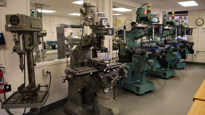
Contents
List of Figures                                                                                                                                      2

List of Tables                                                                                                                                       2

1 Team Summary                                                                                                                                       4
  1.1 Team Location . . . . . . . . . . . . . .                              .   .   .   .   .   .   .   .   .   .   .   .   .   .   .   .   .   .   4
  1.2 Adult Educator Information Information                                 .   .   .   .   .   .   .   .   .   .   .   .   .   .   .   .   .   .   4
  1.3 Student Leadership . . . . . . . . . . . .                             .   .   .   .   .   .   .   .   .   .   .   .   .   .   .   .   .   .   4
  1.4 Team Structure . . . . . . . . . . . . . .                             .   .   .   .   .   .   .   .   .   .   .   .   .   .   .   .   .   .   4
  1.5 NAR/TRA Sections . . . . . . . . . . .                                 .   .   .   .   .   .   .   .   .   .   .   .   .   .   .   .   .   .   8
  1.6 Time Spent on Proposal . . . . . . . . .                               .   .   .   .   .   .   .   .   .   .   .   .   .   .   .   .   .   .   8

2 Facilities and Equipment                                                                                                                            8
  2.1 Accessible Equipment . . . .               .   .   .   .   .   .   .   .   .   .   .   .   .   .   .   .   .   .   .   .   .   .   .   .   .    9
  2.2 Accessible Software . . . . .              .   .   .   .   .   .   .   .   .   .   .   .   .   .   .   .   .   .   .   .   .   .   .   .   .   12
  2.3 Communication Equipment                    .   .   .   .   .   .   .   .   .   .   .   .   .   .   .   .   .   .   .   .   .   .   .   .   .   12
  2.4 Testing Sites . . . . . . . . .            .   .   .   .   .   .   .   .   .   .   .   .   .   .   .   .   .   .   .   .   .   .   .   .   .   12

3 Safety                                                                                                                                             12
  3.1 NAR/TRA Personnel Procedures .                             .   .   .   .   .   .   .   .   .   .   .   .   .   .   .   .   .   .   .   .   .   18
  3.2 Student Safety Briefings . . . . . .                       .   .   .   .   .   .   .   .   .   .   .   .   .   .   .   .   .   .   .   .   .   19
  3.3 Caution Statements . . . . . . . . .                       .   .   .   .   .   .   .   .   .   .   .   .   .   .   .   .   .   .   .   .   .   20
  3.4 Law Compliance . . . . . . . . . .                         .   .   .   .   .   .   .   .   .   .   .   .   .   .   .   .   .   .   .   .   .   21
  3.5 NAR/TRA Mentor Motor Handling                              .   .   .   .   .   .   .   .   .   .   .   .   .   .   .   .   .   .   .   .   .   21
  3.6 Written Safety Statement . . . . .                         .   .   .   .   .   .   .   .   .   .   .   .   .   .   .   .   .   .   .   .   .   21

4 Technical Design                                                                                                                                   22
  4.1 Vehicle Specifications . . . . . .                 . . . . . .             .   .   .   .   .   .   .   .   .   .   .   .   .   .   .   .   .   22
  4.2 Projected Altitude . . . . . . .                   . . . . . .             .   .   .   .   .   .   .   .   .   .   .   .   .   .   .   .   .   24
  4.3 Recovery System . . . . . . . .                    . . . . . .             .   .   .   .   .   .   .   .   .   .   .   .   .   .   .   .   .   25
  4.4 Projected Motor . . . . . . . . .                  . . . . . .             .   .   .   .   .   .   .   .   .   .   .   .   .   .   .   .   .   30
  4.5 Projected Payload Design . . .                     . . . . . .             .   .   .   .   .   .   .   .   .   .   .   .   .   .   .   .   .   31
  4.6 Project Requirements . . . . . .                   . . . . . .             .   .   .   .   .   .   .   .   .   .   .   .   .   .   .   .   .   34
  4.7 Major Technical Challenges and                     Solutions               .   .   .   .   .   .   .   .   .   .   .   .   .   .   .   .   .   49

5 STEM Engagement                                                                                                                                    52
  5.1 Plans for STEM Engagement . . . . . . . . . . . . . . . . . . . . . . . .                                                                      52
  5.2 Evaluation Criteria for STEM Engagement . . . . . . . . . . . . . . . . .                                                                      52

6 Project Plan                                                                                                                                       54
  6.1 Project Timeline .     .   .   .   .   .   .   .   .   .   .   .   .   .   .   .   .   .   .   .   .   .   .   .   .   .   .   .   .   .   .   54
  6.2 Budget . . . . . . .   .   .   .   .   .   .   .   .   .   .   .   .   .   .   .   .   .   .   .   .   .   .   .   .   .   .   .   .   .   .   58
  6.3 Funding Plan . . .     .   .   .   .   .   .   .   .   .   .   .   .   .   .   .   .   .   .   .   .   .   .   .   .   .   .   .   .   .   .   61
  6.4 Sustainability Plan    .   .   .   .   .   .   .   .   .   .   .   .   .   .   .   .   .   .   .   .   .   .   .   .   .   .   .   .   .   .   62

                                                             1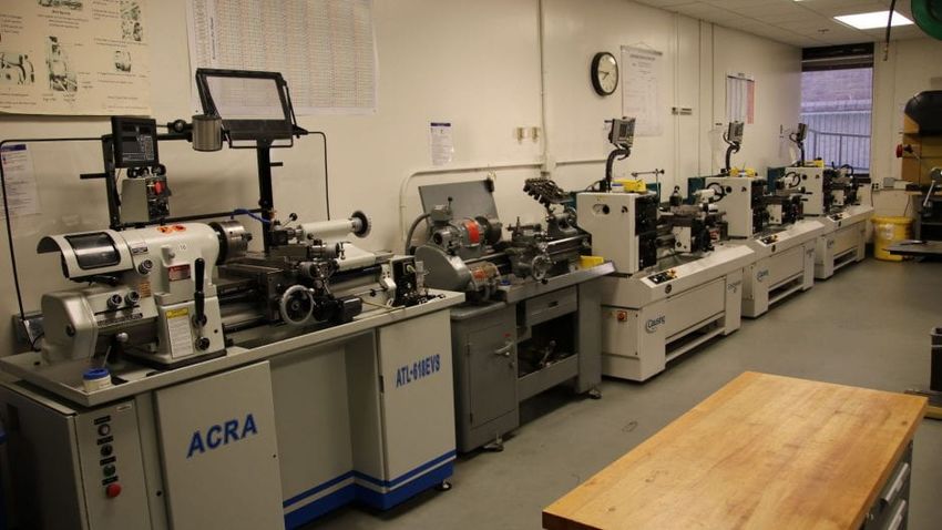
List of Figures
  1    WURocketry Organziation Chart . . . . . . . . . . . . . . . . . .                     .   .   .   .    5
  2    Classroom 120 in Henry A. and Elvira H. Jubel Hall. . . . . . . .                     .   .   .   .    9
  3    Drill press and mills in Urbauer Student Machine Shop. . . . . . .                    .   .   .   .   11
  4    Lathes in Urbauer Student Machine Shop. . . . . . . . . . . . . .                     .   .   .   .   11
  5    Full Rocket Schematic from OpenRocket. . . . . . . . . . . . . . .                    .   .   .   .   22
  6    Decision matrix for nose cone selection. . . . . . . . . . . . . . . .                .   .   .   .   24
  7    Drogue Parachute Recovery Section Planned Packing Diagram . .                         .   .   .   .   25
  8    Main Parachute Recovery Section Planned Packing Diagram . . .                         .   .   .   .   26
  9    Diagram of Recovery System after Drogue Parachute deployment                          .   .   .   .   26
  10   Diagram of Recovery System after Main Parachute Deployment .                          .   .   .   .   27
  11   Recovery System Black Powder Diagram . . . . . . . . . . . . . .                      .   .   .   .   29
  12   Communication System Diagram . . . . . . . . . . . . . . . . . .                      .   .   .   .   30
  13   Thrust vs. Time for Aerotech L1150R-P . . . . . . . . . . . . . .                     .   .   .   .   31
  14   Payload Avionics . . . . . . . . . . . . . . . . . . . . . . . . . . .                .   .   .   .   32
  15   Payload Retention System: Avionics Bay . . . . . . . . . . . . . .                    .   .   .   .   33
  16   STEM Engagement Evaluation Form . . . . . . . . . . . . . . . .                       .   .   .   .   53
  17   STEM Engagement Evaluation Form . . . . . . . . . . . . . . . .                       .   .   .   .   54
  18   WURocketry Schedule 2021-2022 Part 1 . . . . . . . . . . . . . .                      .   .   .   .   55
  19   WURocketry Schedule 2021-2022 Part 2 . . . . . . . . . . . . . .                      .   .   .   .   56
  20   WURocketry Schedule 2021-2022 Part 3 . . . . . . . . . . . . . .                      .   .   .   .   57
  21   WURocketry Schedule 2021-2022 Part 4 . . . . . . . . . . . . . .                      .   .   .   .   57

List of Tables
  1    Adult Educator Information . . . . . . . . . .      . . . . . .   .   .   .   .   .   .   .   .   .    4
  2    Student Leadership Information . . . . . . . .      . . . . . .   .   .   .   .   .   .   .   .   .    4
  3    NAR/TRA Sections . . . . . . . . . . . . . .        . . . . . .   .   .   .   .   .   .   .   .   .    8
  4    Time Spent on Proposal Review Broken Down           by Group      .   .   .   .   .   .   .   .   .    8
  5    Available Equipment . . . . . . . . . . . . . .     . . . . . .   .   .   .   .   .   .   .   .   .   10
  6    Launch Locations Accessible to WURocketry .         . . . . . .   .   .   .   .   .   .   .   .   .   12
  7    Risk Assessment Categories . . . . . . . . . .      . . . . . .   .   .   .   .   .   .   .   .   .   13
  8    Risk Severity Categories . . . . . . . . . . . .    . . . . . .   .   .   .   .   .   .   .   .   .   13
  9    Risk Assessment of Materials and Facilities . .     . . . . . .   .   .   .   .   .   .   .   .   .   14
  10   Aerotech L1150 Specifications . . . . . . . . .     . . . . . .   .   .   .   .   .   .   .   .   .   31
  11   General NASA USLI Requirements . . . . . .          . . . . . .   .   .   .   .   .   .   .   .   .   34
  12   Vehicle Requirements . . . . . . . . . . . . . .    . . . . . .   .   .   .   .   .   .   .   .   .   37
  13   Recovery System Requirements . . . . . . . .        . . . . . .   .   .   .   .   .   .   .   .   .   41
  14   Payload Requirements . . . . . . . . . . . . .      . . . . . .   .   .   .   .   .   .   .   .   .   44
  15   Safety Requirements . . . . . . . . . . . . . .     . . . . . .   .   .   .   .   .   .   .   .   .   47
  16   Launch Vehicle Technical Challenges . . . . .       . . . . . .   .   .   .   .   .   .   .   .   .   49
  17   Recovery System Technical Challenges . . . .        . . . . . .   .   .   .   .   .   .   .   .   .   49
  18   Payload System Technical Challenges . . . . .       . . . . . .   .   .   .   .   .   .   .   .   .   51
  19   Structures Budget . . . . . . . . . . . . . . . .   . . . . . .   .   .   .   .   .   .   .   .   .   58
  20   Avionics Budget . . . . . . . . . . . . . . . . .   . . . . . .   .   .   .   .   .   .   .   .   .   58
  21   Recovery Budget . . . . . . . . . . . . . . . .     . . . . . .   .   .   .   .   .   .   .   .   .   59
  22   Propulsion Budget . . . . . . . . . . . . . . .     . . . . . .   .   .   .   .   .   .   .   .   .   59

                                           2
23   Payload Budget . . . . . . . .    .   .   .   .   .   .   .   .   .   .   .   .   .   .   .   .   .   .   .   .   .   .   .   .   59
24   Sub-scale Rocket Budget . . .     .   .   .   .   .   .   .   .   .   .   .   .   .   .   .   .   .   .   .   .   .   .   .   .   60
25   Manufacturing Budget . . . .      .   .   .   .   .   .   .   .   .   .   .   .   .   .   .   .   .   .   .   .   .   .   .   .   60
26   STEM Engagement Budget .          .   .   .   .   .   .   .   .   .   .   .   .   .   .   .   .   .   .   .   .   .   .   .   .   60
27   Travel Budget . . . . . . . . .   .   .   .   .   .   .   .   .   .   .   .   .   .   .   .   .   .   .   .   .   .   .   .   .   61
28   Total Budget . . . . . . . . .    .   .   .   .   .   .   .   .   .   .   .   .   .   .   .   .   .   .   .   .   .   .   .   .   61
29   Contributors to WURocketry        .   .   .   .   .   .   .   .   .   .   .   .   .   .   .   .   .   .   .   .   .   .   .   .   62

                                               3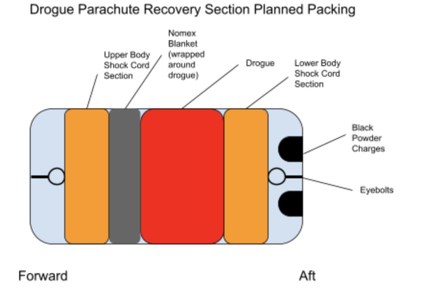
1     Team Summary
1.1     Team Location
    Washington University in St. Louis’s Rocket Team’s (WURocketry) mailing address
is: Lopata 303, 1 Brookings Drive St. Louis, MO 63105.

1.2     Adult Educator Information Information
   WURocketry’s mentor is Mike Walsh. WURocketry’s staff advisor from Washing-
ton University in St. Louis is Ashleigh Goedereis. Contact information for each adult
educator is listed in Table 1.

                               Table 1: Adult Educator Information
 Name                        Michael Walsh                            Ashleigh Goedereis
                             Engineering Analyst - Casting for Toy-
 Professional Title                                                   Assistant Dean for Student Advising
                             ota Motor Manufacturing
 Position             with
                             Mentor                                   Staff Advisor
 WURocketry
                             Michael.Walsh@toyota.com, (636) 358-
 Contact Information                                                  agoedereis@wustl.edu, (314) 935-4577
                             2490
 NAR/TRA Number,             TRA: 09969, NAR: 85317, Certification
                                                                      N/A
 Certification Level         Level 3

1.3     Student Leadership
    WURocketry has three main student leaders, which are listed below in Table 2.

                             Table 2: Student Leadership Information
 Name                            Caitlind Walker             Siyuan Ma                Alexander Posly
                                 President and Project
 Position with WURocketry                                    Chief Engineer           Safety Officer
                                 Manager
                                 caitlindwalker@wustl.edu,   siyuan.ma@wustl.edu,     alexanderposly@wustl.edu,
 Contact Information
                                 (636) 439-0795              (651) 894-3404           (570) 903-5887
 NAR Number                      109147                      291894                   291893

1.4     Team Structure
    The team is compromised of 24 students. Each member is placed on a sub-team, which
is responsible for a subsystem of the rocket. The WURocketry team further includes
a business/funding chair, a STEM Engagement chair, and a social media chair. The
position of each student is shown in Figure 1, which illustrates the organizational chart
for WURocketry.

                                                    4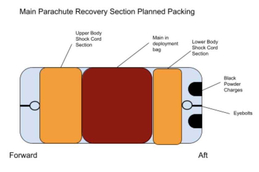
Figure 1: WURocketry Organziation Chart

   The positions and responsibilities of each student leadership role are listed below. The
positions follow the organization chart in Figure 1 from top to bottom, left to right.

   President and Program Manager

   • Acts as representative of the team to NASA and Washington University in St.
     Louis, including maintaining dialogue and reporting on progress

   • Collaborates with elected officials to appoint leader and members’ roles

   • Presides over meetings and ensures communication between sub-teams

   • Schedules design, manufacturing, and testing phases and ensures adherence to the
     schedules

   • Works on all reports to ensure they are completed in a timely manner

   • Takes the lead with the chief engineer on presentations of reports

   • Moderates conflicts

   • Ensures adherence to team constitution

   • Develops measures to ensure knowledge transfer and continuance of the organization
   Treasurer

   • Leads in creation of budget plan

   • Ensures budget plan is adhered to and reports accordingly

                                            5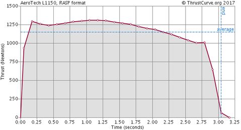
• Processes reimbursements for team members

• Maintains accounts

• Summarizes accounts status for successor

• Point of contact for the Cost Report

Safety Officer

• Monitor team activities with an emphasis on safety during:

    – Design of vehicle and payload
    – Construction of vehicle and payload components
    – Assembly of vehicle and payload
    – Ground testing of vehicle and payload
    – Subscale launch test(s)
    – Full-scale launch test(s)
    – Launch day
    – Recovery activities
    – STEM Engagement Activities

• Implement procedures developed by the team for construction, assembly, launch,
  and recovery activities.

• Manage and maintain current revisions of the team’s hazard analyses, failure modes
  analyses, procedures, and MSDS/chemical inventory data.

• Assist in the writing and development of the team’s hazard analyses, failure modes
  analyses, and procedures.

Chief Engineer

• Ensures the sub-teams follow good engineering practices

• Performs design reviews with sub-teams to ensure their designs are technically sound

• Oversees build of all rockets and payloads

• Takes the lead with the program manager on presentations of reports

Social Media Chair

• Responsible for maintaining social sites and posting weekly

• Maintains the team webpage and updates the site with all documentation through-
  out the competition

STEM Engagement Chair

                                         6
• Responsible for the planning and execution of the community outreach events
• Works with other organizations to create community outreach events
Business/Funding Chair
• Creates and presents proposals to request funding from various funding sources
• Actively pursues sponsorships from companies
Payload Sub-Team Lead
• Assigns tasks to payload team members
• Ensures the payload team is meeting their schedule
• Trains new payload team members
• Coordinates with other sub-teams leads to ensure the payload will integrate with
the rocket
Structures Sub-Team Lead
• Assigns tasks to structures team members
• Ensures the structures team is meeting their schedule
• Trains new structures team members
• Coordinates with other sub-teams leads to ensure the structures’ components will
integrate with the rocket
Recovery and Propulsion Sub-Team Lead
• Assigns tasks to recovery and propulsion team members
• Ensures the recovery and propulsion team is meeting their schedule
• Trains new recovery and propulsion team members
• Coordinates with other sub-teams leads to ensure the recovery and propulsion com-
ponents will integrate with the rocket
Avionics Sub-Team Lead
• Assigns tasks to avionics team members
• Ensures the avionics team is meeting their schedule
• Trains new avionics team members
• Coordinates with other sub-teams leads to ensure the avionics’ components will
integrate with the rocket
71.5 NAR/TRA Sections
WURocketry will be working with the St. Louis Rocketry Association, the Tripoli
Mo-Kan Section, and the Quad Cities Rocket Club for mentoring and launch assistance.
The information for each section is shown in Table 3.
Table 3: NAR/TRA Sections
Section NAR/TRA Number Launch Location
St. Louis Rocketry Association (SLRA) #551 (NAR) Elsberry, MO
Tripoli Mo-Kan #101 (TRA) Walnut Grove, MO
Quad Cities Rocket Club #678 (NAR), #39 (TRA) Ohio, IL
1.6 Time Spent on Proposal
The time WURocketry has spent on the proposal is outlined in Table 4.
Table 4: Time Spent on Proposal Review Broken Down by Group
Recovery & Business/ STEM En- Executive
Group Avionics Payload Structures Total
Propulsion Funding gagement Team
Time
12 24 27 11 5 2 40 121
(Hours)
2 Facilities and Equipment
All general team meetings during WURocketry’s 2021-2022 season are located in
Henry A. and Elvira H. Jubel Hall on Washington University in St. Louis campus.
Major manufacturing and assembly take place in either of the two machine shops on
campus or in the makerspace.
8Figure 2: Classroom 120 in Henry A. and Elvira H. Jubel Hall.
2.1 Accessible Equipment
All team members have been trained to use the makerspace, and specific members
of the WURocketry team have access to both machine shops. Access to these areas
require students to either complete machine shop practicum courses or online and in-
person training under the guidance of the shop foreman and manager. Furthermore,
the machine shop requires at least one monitor who has also completed the necessary
training. The machine shops are open for students from 10am to 5pm on weekends. The
makerspace is open for students from 10am to 5pm on weekdays and weekends, but the
team can schedule additional time outside of this hours. The available equipment in the
makerspace and machine shop are listed in Table 5. The team must provide the raw
materials used in the construction of the launch vehicle.
9Table 5: Available Equipment
Machine Shop
Equipment:
• Manual and CNC Mill
• Manual and CNC Lathe
• Drill Press
• Bandsaw
• Surface Grinder
• Mig Welder
• Tig Welder
• Spot Welder
• Oxygen Acetylene Torch
• Hand Tools and Power Tools
Makerspace
Equipment:
• 3D Printer (SLA, FDM)
• Laser Cutter
• Sewing Machine
• Vinyl Cutter
• Oscilloscope
• Power Supply
• Function Generator
• General Hand Tools and Power Tools
• Electronics Bench with Soldering Iron
10Figure 3: Drill press and mills in Urbauer Student Machine Shop.
Figure 4: Lathes in Urbauer Student Machine Shop.
112.2 Accessible Software
All WURocketry team members have access to the following software via the desktops
in the computer labs or their personal computers.
• MATLAB
• Solidworks
• Autodesk Fusion360
• Autodesk Inventor
• AutoCAD
• OpenRocket
• Microsoft Office
• Adobe
2.3 Communication Equipment
Classrooms and lecture halls are available for WURocketry and are equipped with
computer with internet access, conference telephone with speaker, projector, and mi-
crophones for video conferencing of Preliminary Design Review (PDR), Critical Design
Review (CDR), and Flight Readiness Review (FRR) to the panel of National Aeronautics
and Space Administration (NASA) personnel.
2.4 Testing Sites
Table 6: Launch Locations Accessible to WURocketry
Distance from
Name Field Location Capabilities/Uses
Campus
Old Hwy 79, Elsberry, High Power Launches
Elsberry 1 Hour
MO 63343 6,500 ft.
23550 1850 E., Ohio, High Power Launches
Ohio IL Launch Site 4 Hours
IL 61349 10,000 ft.
5612 South 10th Road,
High Power Launches
Walnut Grove Walnut Grove, MO 4 Hours
15,000 ft.
65770
3 Safety
The following sections are written as a set of safety guidelines for WURocketry. These
sections cover the safety of materials used and facilities involved. The primary student
responsible for the execution of these guidelines is the Safety Officer, Alexander (Alex)
Posly. In the case that Alex is unavailable, the President and Program Manager, Caitlind
Walker, is responsible. All machining will be overseen by either Alex or the Chief Engi-
neer, Siyuan Ma.
12To properly assess the risks involved in the NASA SL project, a categorization of
likelihood was applied to any potential source of harm to team members and to the
project. The categorization was developed by surveying the experiences of the most
senior team members and the team mentor. Therefor, these categories are not definitive
and are only meant to serve members and the safety officer as a guide for safe conduct.
The categories are listed below.
Table 7: Risk Assessment Categories
Category Represented
Percentage
Range
Rare 0% - 25%
Unlikely 25% - 50%
Possible 50% - 75%
Likely 75% - 100%
An important note on these categories: each percentage range and category is not
representative of the certainty of injury. Each is meant to illustrate the caution required
for different sources of harm or damage. Using the above structure, a risk analysis was
completed on the materials and facilities that will be used to complete the project.
In addition to the likelihood categories, we constructed a severity category system.
The system, in contrast with the likelihood schema, utilizes qualitative descriptions of
the consequences of a failure. Similarly to the likelihood schema, the severity scale was
developed by surveying with consensus of experience from senior members as well as the
team mentor. Below is the categorization of each level of severity.
Table 8: Risk Severity Categories
Category Severity To Human Severity To Rocket
Minor Injury requiring no treat- Superficial damage to
ment. rocket requiring no repair.
Moderate Injury requiring some med- Damage to the rocket re-
ical care/treatment (ban- quiring some repairs (re-
dage, ice, etc.). tighten hardware, re-align
component, etc.)
Major Injury requiring pro- Damage requiring sig-
fessional medical nificant repair (Patching
care/treatment (sutures, parachute, correcting bent
concussion protocol, etc.) components, etc.)
Severe Injury requiring hospital- Damage requiring purchase
ization or other prolonged of entirely new component
treatment
The following is a table denoting the risk assessment of the materials and the facilities
for the project. Specific materials and equipment that were mentioned in section X of
this report have been grouped into broader types when possible. For example, a CNC
Mill and a Drill Press are grouped into machining equipment due to the similar risk and
training involved in their operation.
13Table 9: Risk Assessment of Materials and Facilities
Risk Likelihood Cause Effect Severity Mitigation Verification
Damage to or Unlikely Inappropriate Slight physical Minor Choice of hardware guided Testing completed and
from hardware sizing; Incorrect harm to by senior member’s expe- checked by team lead with
tightening tool; body: abra- rience and testing prior to the executive board; Safety
Over loading; sions/contusions; application; Assemblers Officer maintains a log of
Incorrect choice Slight damage trained according to school each member’s completed
of hardware to rocket: facilities’ rules; Safety Offi- training; Assembly supervi-
scratches/dents cer responsible for monitor- sor provides safety briefing
ing all construction prior to beginning work
Damage from Possible Insufficient per- Harm to res- Moder- Safety Officer responsible Safety Officer maintains a
epoxy to mem- sonal protec- piratory sys- ate for monitoring all construc- log of each member’s com-
bers or rocket tive equipment tem; Exposure tion; Available material pleted training; Safety Of-
(PPE); Incor- to fumes; Ero- safety data sheet (MSDS) ficer completes checklist
rect facility sion of compo- for member’s; Training of facility’s ventilation for
14
requirements; nents; Insuffi- conducted by Chief Engi- fumes; Trained members
Ignorance of cient bonding of neer for all member’s using confirm preparation proce-
preparation pro- parts epoxy; Assembly supervi- dures properly executed
cedures sor provides safety briefing
prior to beginning work
Damage from Rare Incorrect stor- Injury from Major Available material safety Safety Officer maintains
battery over age; Incorrect burns or data sheet (MSDS) for a checklist of storage re-
heating, com- connection; In- projectiles; Im- member’s; Training con- quirements; Avionics team
bustion, or ex- correct usage paired/destroyed ducted by Chief Engineer lead supervises member’s
plosion estimation to electronics; for all member’s handling battery usage and storage
Introduction of batteries; Test battery con-
insecurities to nection and power produc-
rocket structure tion outside of structureDamage from Possible Incorrect use of Lacerations, Severe Assemblers trained ac- Choice of parts checked by
machining equipment; In- abrasions, cording to school facilities’ Chief Engineer; List of cer-
equipment correct cut tech- bruises, bro- rules; Machining conducted tified personnel maintained
nique; Incorrect ken bones, head according to school rules by Safety Officer; Safety
tool choice injury; Broken with professional or certi- Officer maintains a log of
components; fied user supervision each member’s completed
High repair training
costs
Damage from Rare Forced usage; Lacerations, Minor Assemblers trained ac- Safety Officer or team lead
manual tools Incorrect tool abrasions, cording to school facilities’ confirms tool choice for
for work; Insuf- bruises, punc- rules; Safety Officer holds construction; Safety Offi-
ficient fixture; ture wounds; annual briefing on basic of cer maintains a log of each
Incorrect PPE Broken tools; manual tools; All construc- member’s completed train-
Incomplete fas- tion supervised by Safety ing
tening; Dents or Officer or team lead
15
scratches
Damage from Unlikely Incorrect electri- Lacerations, Moder- Assemblers trained ac- Choice of parts checked by
power tools cal connections; abrasions, ate cording to school facilities’ Chief Engineer; List of cer-
Forced usage; bruises, bro- rules; Machining conducted tified personnel maintained
Incorrect tool ken bones, head according to school rules by Safety Officer; Safety
for work; Insuf- injury; Broken with professional or certi- Officer maintains a log of
ficient fixture; components; fied user supervision each member’s completed
Incorrect PPE Electrocution trainingDamage from Unlikely Incorrect place- Shrapnel in- Severe Only certified personnel Safety Officer maintains
explosives ment; Incorrect juries; Signif- handle explosives; Men- log of all certified mem-
preparation; In- icant bodily tor supervises all explosive bers; Mentor confirms all
correct estimate harm; Burns; handling; Mentor stores all preparations and connec-
of explosiveness Destroyed explosives tions completed properly
equipment; De-
stroyed compo-
nents
Damage from Possible Incorrect iron Burns; Respi- Minor School training completed Safety Officer maintains
soldering temperature; ratory damage; prior to soldering; Solder- log of all certified mem-
Improper venti- Electrocution; ing completed only in veri- bers; Mentor confirms all
lation; Incorrect Insufficient con- fied facilities; Soldering su- preparations and connec-
technique nection; damage pervised by Avionics lead tions completed properly;
to components Safety Officer confirms lo-
cation of soldering
16
Injury from Likely Incorrect PPE; Slivers from ma- Moder- Only certified personnel Safety Officer maintains
fiber glass Incorrect tech- terial; Skin irri- ate handle fiber glass; MSDS log of certified personnel;
nique tation available during all con- Safety Officer provides reg-
struction processes; Team ular briefing on construc-
lead supervises construc- tion materials; Safety Offi-
tion cer supervises construction
Damage to or Likely Insufficient Significant dam- Severe All members required to Safety Officer maintains
from use of training; Im- age to school complete school training; log of all certified mem-
Maker’s Space proper supervi- tools and ma- All members required to bers; Safety Officer or
or Machine sion; Insufficient chines; Serious sign team and school safety other executive member
Shop PPE injury caused by documents; All use of facil- supervises construction;
misuse of equip- ities must be supervised School maintains log of all
ment certified studentsDamage to or Unlikely Insufficient Injuries related Mild Only lead members allowed Safety Officer confirms
from mentor’s PPE; Incorrect to use of hand to use mentor’s facility; planned use of mentor’s
facility technique tools; Damage Executive member and facility; Mentor confirms
to components mentor required at facil- use of facility and any tools
of rocket ity
Damage from or Possible Insufficient Serious injuries Severe All members required to Safety Officer maintains
to launch range training; Non- due to rocket attend safety brief prior log of all certified mem-
compliance malfunctions; to launch; Safety Officer bers; Safety Officer su-
with regula- Significant dam- confirms rocket launch con- pervises all launch activ-
tions; Incorrect age to rocket ditions with Range Officer; ities; All members required
construction of body or compo- Executive members and to abide by safety pro-
rocket nents mentor required at launch cedures during construc-
tion/preparation of rocket
173.1 NAR/TRA Personnel Procedures
To comply with NAR High Power Safety Code requirements, all members will be
briefed on the thirteen requirements and distance tables. The following procedures will
be required for all rocket activities based on the thirteen requirements:
1. Certification. WURocketry will not launch high powered rockets with out the
supervision of a certified mentor. The team’s mentor is Mike Walsh who has the
necessary L3 certification. Also the President and Avionics Lead both hold L2
certifications for sub scale launches.
2. Materials. WURocketry prioritizes the use of lightweight materials and ductile
metals as described by the NAR codes. The materials chosen are verified by the
Chief Engineer and the Safety Officer for compliance with NAR codes. The weight
of the vehicle is also considered during the duration of the design process.
3. Motors. WURocketry requies that all motors be handled, prepared, and stored
by the team mentor. The motors are only available to certified members during
launches and are handled under the super vision of the Safety Officer. Per NAR
codes, no potential ignitors of the motor are prohibited near the motor during
launches. The Safety Officer is responsible for ensuring that this code is followed.
4. Ignition System. WURocketry, under the direction of the team mentor, has designed
a motor ignition system that is modular and electric. The full system cannot be
installed until the rocket is on the launch pad and can only be installed by certified
members under the supervision of the Safety Officer. All ignition systems will be
designed to only function when the rocket is prepared and on the launch pad. The
rocket will also be designed to have a safety interlock connected in series with the
ignition switch.
5. Misfires. If a misfire occurs, WURocketry members will not approach the rocket
for at least 60 seconds. The safety interlock will be removed and any batteries will
be disconnected.
6. Launch Safety. WURocketry will follow specific procedures during launches that
will protect members and bystanders. A five second verbal countdown will be
utilized as well as a final safety check for distance from the rocket. Both will be
conducted by the Safety Officer. WURocketry has deemed the team mentor, the
President, and the Chief Engineer the only members to arm the rocket. The Chief
Engineer will be responsible for a final stability check of the rocket, and the Safety
Officer will be responsible for verifying that the prescribed steps have been taken.
7. Launcher. WURocketry will abide by specific required distances listed by NAR
codes during launch. WURocketry will also utilize required launch rails and pads
from NASA SL. The Safety Officer will verify the distance requirements, and the
Chief Engineer will verify the launch pad stability.
8. Size. WURocketry’s proposed motor is under the 40960 N-sec requirement listed in
the NAR codes. The weight of the rocket will consistently be re-calculated during
the design portion of the competition. The Chief Engineer will be responsible for
confirming the weight and motor selection of the rocket.
189. Flight Safety. WURocketry’s Safety Officer will confirm all launch conditions in-
cluding weather, FAA regulations, and bystander locations with the Range Safety
Officer prior to initiating any launch sequence.
10. Launch Site. WURocketry will only launch rockets at NAR certified launch loca-
tions. Each location will be verified by the Safety Officer to have the necessary
certification.
11. Launcher Location. WURocketry will only launch rockets at NAR certified launch
locations. Upon arrival the Safety Officer will discuss with the Range Safety Officer
where the launch pad will be set. The Safety Officer will also verify the distances
from any structure or road.
12. Recovery System. WURocketry has selected a non-flammable droug and main
parachute. The rocket will be designed to use these parachutes to reduce kinetic
energy sufficiently as to not cause damage to the rocket. WURocketry will design
the rocket to be re-used after launch with in 2 hours.
13. Recovery Safety. WURocketry will require all members to maintain in the same
position after rocket launch until the rocket safely reaches the ground. The Safety
Officer will verbally verify when members may approach the rocket. In the case
that the rocket is stuck on a power-line, tree, or any structure. The Safety Officer
will consult with the Range Safety Officer to contact the proper authorities to safely
recover the rocket.
14. Hazardous Materials. WURocketry’s Safety Officer will keep and maintain a MSDS
which will be available at any WURocketry meeting. The MSDS will contain in-
formation on any hazardous material that is used during the construction of the
rocket. All members will be required to review the MSDS prior to handling a haz-
ardous material. Any member may also contribute new information to the MSDS
by informing the Safety Officer.
3.2 Student Safety Briefings
The Safety Officer will be responsible for providing safety briefings regularly to all
members. To do this, regular, pre-testing, pre-construction, and pre-launch and post-
launch briefings will be held. In the case that the Safety Officer or any other team
member witnesses any violation of safety procedures, additional briefings will be held to
avoid more violations. The following are the plans for each type of briefing.
1. Regular Safety Briefings (RSB) will be held during the first week, the half way
point, and the last week before competition. Each will be lead by the Safety Officer
and will cover the general safety guidelines laid out by NASA SL, NAR/TRA codes,
Washington University, and WURocketry. Members will be informed about where
to find crucial documents like the MSDS or safety procedures. They will also learn
about who is responsible in certain areas of work, such as identifying the Safety
Officer, the team mentor, and back up safety contacts. Finally, members will be
informed about who to contact in case of emergency.
2. Pre-testing Safety Briefings (pTSB) will be held prior to any testing. These brief-
ings will require team leads who are conducting the testing to fill out informational
19documentation at least one week in advance. The Safety Officer will review the
document ad gather necessary safety documents, procedures, and general warn-
ings/advice. On the day of the test, the Safety Officer will gather the sub-team
responsible for the test and explain the necessary pre-cautions for the test. Addi-
tionally, the Safety Officer will provide the team with any gathered safety docu-
mentation pertinent to the test. After verbally confirming the procedures, the test
will begin.
3. Pre-construction Safety Briefings (pCSB) will be conducted similarly to pTSBs.
Responsible members for the construction of any component will submit informa-
tional documentation to the Safety Officer for review. The Safety Officer will then
gather any information necessary for the procedure to be conducted safely. Prior to
construction via verbal communication, the Safety Officer or an executive member
will detail the safety guidelines for the construction.
4. Pre-launch Safety Briefings (pre-LSB) will be held as a team prior to any launch.
The Safety Officer will ensure all participating members will gathering prior to any
launch to review general safety guidelines. These guidelines will be read verbally.
After this general gathering, the Safety Officer will meet with each sub-team to
discuss the procedures concerning their portion of the rocket. These procedures
will be finalized during the early design stages of the competition. After each
sub-team is briefed on their procedures, the Safety Officer will verbally confirm
understanding and ask for any questions. If no questions occur, the Safety Officer
will proceed to the next sub-team until the rocket is fully prepared for launch.
5. Post-launch Safety Briefings (post-LSB) will be had after any launch. These brief-
ings will be held by the Safety Officer to discuss any issues during launches. If
any specific incidents occur, the Safety Officer will review the incident and explain
what went wrong and how to fix the problem. Each launch is a long and complex
process which is why WURocketry will require post-LSBs. At the conclusion of
each post-LSB, the Safety Officer will add any new safety documentation to the
safety binder that includes all safety procedures.
3.3 Caution Statements
During the construction, testing, and launching of the rocket, WURocketry will utilize
the the Globally Harmonized System of Classification and Labelling of Chemicals (GHS).
This system allows for a streamlined pictoral representation of hazards associated with
materials. The symbols will be added to any procedure that uses hazardous materials.
A glossary of these symbols will also be available in the MSDS.
PPE requirements will be listed prior to any step that requires it in a procedure. At
the beginning of the procedure, a correct location to conduct the work will be listed then
step by step instructions with PPE listed in italics before the step. All PPE will be made
available either through the school or through the Safety Officer. Prior to starting work
the Safety Officer will also brief the members on the required PPE. During work, the
Safety Officer will consistently check to ensure proper PPE is being used. If it is not, the
Safety Officer will stop work until the PPE is obtained.
203.4 Law Compliance
WURocketry will comply with the necessary regulations including 14 CFR, Subchap-
ter F, Part 101, Subpart C; 27 CFR 55: Commerce in Explosives; and NFPA 1127. The
responsibility of reading and understanding these regulations falls on the Safety Officer.
After reading them, the Safety Officer will be the point of contact for any member to learn
more about each. The Safety Officer will explain these regulations during the first Safety
Briefing of the year. The information presented on the regulations will include information
from 14 CFR 101 regarding class 2 rockets, operating limitations, and notification of ATC
and FAA bodies. From 27CFR 55, members will be informed on proper licensing, storage,
and fire control. Finally, from NFPA 1127, members will learn about the requirements for
high powered rocket construction, user certifications, and prohibited activities regarding
high powered rockets. Each major subsections of the regulations will be added to a
checklist for the Safety Officer to complete during applicable processes. If the Safety
Officer is not available, a designated member of the team will be appointed to review
necessary regulations.
3.5 NAR/TRA Mentor Motor Handling
WURocketry’s mentor will be responsible for the purchasing, storing, and handling
of both the rocket motor and the black powder. WURocketry’s mentor is required to
be certified to handle said materials and will transport them to necessary WURocketry
events. Any time the mentor is unavailable only appropriately certified team members
will handle the motor and energetic devices. The Safety Officer will maintain a list of
appropriately certified members. During the preparation of the motor, no uncertified
member will be permitted to handle energetic devices. The Safety Officer will supervise
all preparations and ensure compliance with regulations.
3.6 Written Safety Statement
I, hhhhhhhhhhhhhhhhhhhhhhhhhhhhhhhhhh , understand and will abide by the fol-
lowing safety regulations from the National Aeronautics and Space Administration Stu-
dent Launch Handbook and Request for Proposal:
1.6.1. Range safety inspections will be conducted on each rocket before it is flown.
Each team shall comply with the determination of the safety inspection or may be re-
moved from the program.
1.6.2. The Range Safety Officer has the final say on all rocket safety issues. There-
fore, the Range Safety Officer has the right to deny the launch of any rocket for safety
reasons.
1.6.3. The team mentor is ultimately responsible for the safe flight and recovery of
the team’s rocket. Therefore, a team will not fly a rocket until the mentor has reviewed
the design, examined the build and is satisfied the rocket meets established amateur rock-
etry design and safety guidelines.
1.6.4. Any team that does not comply with the safety requirements will not be al-
lowed to launch their rocket.
21Signature:hhhhhhhhhhhhhhhhhhhhhhhhhhhhhhhhhh
Date:hhhhhhhhhhhhhhhhhhhhhhhhhhhhhhhhhh
4 Technical Design
4.1 Vehicle Specifications
This year is WURocketry’s second year competing in NASA University Student
Launch Initiative (USLI). The team designed and built a launch vehicle for 2020 NASA
Student Launch competition using the information gathered from research. This year,
the team was able to build on the knowledge and experience gained during last year’s
competition in the development of the rocket for the 2021 NASA Student Launch com-
petition. The team used OpenRocket software to simulate the performance of the rocket
and make necessary design changes based on simulation results. The schematic of the
proposed rocket for the 2021 NASA Student Launch competition is shown in Figure 5.
Figure 5: Full Rocket Schematic from OpenRocket.
The launch vehicle consists of forward, mid, and aft sections. These sections have been
divided based on the proposed in-flight separation points necessary for the deployment
of the main and drogue parachutes, as well as the ease of manufacturing, assembly, and
transportation of the rocket. Different options for the diameter of the following sections
were considered. an airframe with an inner diameter of 5.375 in. and outer diameter
of 5.525 in. was selected to keep the weight and the cost of the airframe low while pro-
viding enough space for the storage of payload, the flight computers, and the recovery
systems. G12 fiberglass filament wound tubes were chosen for the airframes based on
the team’s analysis and satisfaction with the performance of last year’s launch vehicle’s
airframes. The rocket is mainly composed of fiberglass, aluminum, and plywood as well
as some additively manufactured components. When the known and estimated masses
of the components of the rocket are summed up, the wet mass is calculated to be 33.69
lb and the dry mass is 29.11.
22The total length of the rocket is 89.7 in with the forward, mid, and aft sections mea-
suring 47.325 in, 27.25 in, and 15.125 in, respectively. The location of the center of
gravity (CG) is 53.744 in below the tip of the nose cone, while the location of center of
pressure (CP) is 67.244 in below the tip of nose cone. The resulting margin of stability
was determined in OpenRocket to be 2.44.
The forward section of the rocket is made up of 3:1 ogive nose cone, payload, payload
deployment mechanism, drogue parachute, shock cords, and a bulkhead. There is an
in-flight separation point located in between the front and mid sections. The drogue
parachute is to be released from this separation point.
The mid-section is made up of the avionics bay, coupler connecting the forward and
mid section, two bulkheads, and the main parachute with the attached shock cords. The
avionics bay will be located entirely in the coupler between two bulkheads secured via
threaded rods. The bulkhead at the top of the avionics capsule is attached to the forward
airframe with four 4-40 nylon shear pins. The bulkhead at the bottom of the of the cap-
sule is attached to the mid airframe with four 6-32 stainless steel screws. An anti-zipper
design is used for this coupler in order to prevent the shock cords from ripping through
the airframe due to the snatch force.
The aft section consists of the coupler connecting the mid and aft section, fins, motor,
motor retention and mounting mechanism, and centering rings. The coupler is perma-
nently attached to the aft section and is connected to the mid airframe with four 4-40
nylon shear pins. The coupler that connects mid and aft sections is also developed with
an anti-zipper design. The fins are connected to the centering rings and are epoxied into
the airframe.
4.1.1 Material Choice
The airframe will be machined out of of 5.525 in. diameter G12 fiberglass filament
wound tubes. G12 fiberglass was chosen due to its suitable strength-to-weight ratio,
RF transparency, cost effectiveness, commercial availability, and WURocketry’s previous
use and knowledge of the material. Carbon fiber and G10 fiberglass were materials
considered for the rocket as well but not chosen. Carbon fiber has a higher strength-to-
weight ratio than G12 fiberglass, but is more expensive, not as readily available, and is
not RF transparent. G10 fiberglass is very similar to G12 fiberglass, only varying in the
orientation of its fibers. G10 fiberglass has a higher strength-to-weight ratio than G12
fiberglass, but is not as readily available. Since WURocketry used G12 fiberglass last
year, using the same material again will allow the team to focus its resources and time
on improving other components of the rocket.
4.1.2 Nose Cone
The nose cone is an important piece of the assembly as it affects the drag force and
balance of the rocket. WURocketry decided to choose a fiberglass 3:1 tangent ogive
shaped nose cone as it is widely available due to its ease of construction and provides
ample strength for our flight conditions. Other shapes for the nosecone were considered,
such as the elliptical, parabolic, and Von Karman shape. These shapes provide a smaller
drag force value but are not as widely available.
23Carbon fiber, plastic, and fiberglass were the three materials considered for the nose
cone. Carbon fiber does have a larger compressive strength than plastic and fiberglass,
but it is expensive, not widely available, and not RF transparent. Plastic is lighter than
carbon fiber, but its compressive strength is lower than that of both carbon fiber and
fiberglass, and plastic nose cones are not widely available. Fiberglass is an optimal choice
for the material of the nosecone as its strength to weight ratio is adequate for the flight
conditions, it is readily available to manufacture and obtain, and it is RF transparent.
Figure 6: Decision matrix for nose cone selection.
A 3:1 tangent ogive nose cone has a greater volume than other nose cones due to
its circular base and large radius of curvature. This gives ample room to house various
components of the rocket including tethers and parachutes. The tangent ogive locates to
the rocket via it’s shoulder. This provides a seamless transition from the nose cone to
the front of the airframe, creating less drag on the rocket.
4.1.3 Fins
The team will be using four equally spaced fins at the base of the launch vehicle. The
fins will be machined out of G10 fiberglass due to its outstanding strength and stiffness.
Fins with a trapezoidal shape and a rectangular cross section were found to be the best
choice for the rocket when taking into account impact resistance, cost, and aerodynamics.
4.2 Projected Altitude
Based on competition requirements, the rocket must reach an altitude between 4,000ft
and 6,000ft. In order to safely stay within this range, this year’s design was optimized for
a projected altitude in the middle of this acceptable range. Using OpenRocket with the
chosen motor and rocket specifications, the team calculated a projected altitude of 5,000
ft. The team wanted to target a mid range apogee because last year’s rocket overshot
its projected altitude by about 500ft. Additionally, this year’s rocket does not include
the air brake system (ABS), as the team recognized that to much time and energy are
needed to improve upon last years design to an appreciable and effective performance
standard. Therefore the team omitted ABS from the design. This could also lead to
a slight overshoot in projected altitude. This year the team will attempt to reach the
target altitude through weight adjustments to the rocket.
244.3 Recovery System
4.3.1 Recovery System Design Layout
The launch vehicle consists of a dual deployment recovery system which is made up
of the main parachute and drogue parachute section. The main parachute section is
made up of an eyebolt connecting to the bulkhead, while the kevlar shock cord (21 ft) is
connected to the deployment bag which contains the main parachute. This 21 ft shock
cord will be connected to the bulkhead in the middle section of the rocket. On the other
side, another kevlar shock cord (18 ft) connects the main parachute to forward retainer
of the motor tube in the aft section of the rocket with an eyebolt. The bulkhead has two
black powder charges which ignite in order for the body tube of the rocket to separate
and release the main parachute. The main parachute is released when the rocket is
falling under the drogue parachute at 600 feet in order for the rocket to lower its terminal
velocity to within the landing kinetic energy limit. The drogue parachute section consists
of two black powder charges connected to the bulkhead. An eyebolt is connected to the
bulkhead where a kevlar shock cord (12 ft) is connected to the eyebolt on the forward
section bulkhead. The other shock cord (15 ft) will be connected to the bulkhead in the
middle body. The kevlar shock cords which are connected from the eyebolts are attached
to the drogue parachute where a nomex blanket is used to prevent the parachute from
catching on fire from the black powder charges. The drogue parachute deploys at apogee.
Figure 7: Drogue Parachute Recovery Section Planned Packing Diagram
25Figure 8: Main Parachute Recovery Section Planned Packing Diagram
Integral to recovery system success is the sequence of events that deploy the parachutes.
At the moment the rocket reaches apogee, the first black powder charge will go off lead-
ing to the first rocket separation and the deployment of the drogue parachute. A second
redundant charge will go off one second later to ensure that the first separation occurs.
The drogue parachute will result in a minimal but necessary slowing of descent that sta-
bilizes the rocket in its initial descent. At 600 ft, another black powder charge will go off,
leading to the second rocket separation and the main parachute will be released. A final
black powder charge, the redundant charge for the second separation, will go off about a
second later at around 500 ft to ensure the second separation occurs successfully.
Figure 9: Diagram of Recovery System after Drogue Parachute deployment
26Figure 10: Diagram of Recovery System after Main Parachute Deployment
4.3.2 Recovery System Calculations
To reach the necessary recovery performance for the rocket, the team utilized several
equations focused on achieving the correct descent time conditions, the kinetic energy
condition, and the drift distance condition. The equations used are below:
Kinematic Energy Equation
1
KE = mv 2 (1)
2
Where KE is the kinetic energy measured in ft-lbf; m is the mass in slugs; v is the
velocity in ft per second.
Drag Force Equation
1
W = Cd Aρv 2 (2)
2
Where W is the weight of the system in lbf; Cd is the coefficient of drag; A is the
effective area; ρ is the atmospheric density; v is the terminal velocity in ft per second.
Area of a Circle with Spill Hole Equation
27A = .96πr2 (3)
Where A is the area in ft2 ; r is the radius in ft.
Given the NASA landing requirement to maintain a landing kinetic energy below 75
ft-lbf, the kinetic energy equation was reordered as follows to solve for the maximum
terminal velocity.
s
2KE
v= (4)
m
After calculating the terminal velocity, the drag force equation was then reworked to
produce the minimum effective area necessary.
2W
A= (5)
Cd ρv 2
Finally, the adjusted area of a circle equation was solved to yield the minimum radius
of the parachute which was converted to the minimum diameter.
s
A
r= (6)
0.96π
Using the progression of the above equations, a minimum diameter of 77.152 in. was
found for the main parachute, and a minimum diameter of 17.239 in. was found for the
drogue parachute. As a result, an 84 in. Iris Ultra Standard parachute from FruityChutes
was chosen for the main parachute, and an 18 in Elliptical parachute from FruityChutes
was chosen for the drogue. Dropping the size of the parachute to 72 inches in diameter
would increase the descent rate, and therefore push the kinetic energy outside of the given
NASA constraint of 75 ft-lbs. An 84 in. parachute is a safe decision in order to maintain
a margin of error in kinetic energy despite the minimum calculated diameter being closer
to 72 inches. The rocket will have a terminal velocity when only the drogue is deployed
of 100.559 ft/s, and a terminal velocity of 17.52 ft/s when the main is deployed.
4.3.3 Recovery System Electronics
The avionics recovery subsystem emphasizes redundancy in its design to minimize the
potential of single-point system failure. This is especially vital for the recovery subsystem,
which is responsible for firing the main and drogue parachute events after the vehicle’s
initial ascent.
The system consists of a set of two commercially available RRC3 Missile Works flight
computers, one serving as a main and another as a backup. The flight computers are each
powered by an individual standard 9V battery, enabling the computers to monitor the
vehicle’s altitude and time the firing of the e-matches during descent. Similarly, there are
two pairs of black powder charges, each pair separating the vehicle at different locations
to ensure deployment of both the drogue and main parachutes. At apogee, the main
flight computer will fire its drogue charge, followed by the delayed firing of the redundant
second flight computer’s drogue charge, one second after apogee, ensuring the release of
the drogue parachute. Then, the main parachute charges will fire in a similar manner at
600 ft and 500 ft AGL to deploy the vehicle’s main parachute.
28Figure 11: Recovery System Black Powder Diagram
4.3.4 Vehicle Tracking
With the goal of achieving a simpler and more reliable design for the rocket communi-
cation system, as compared to last years Project PiONEER system, the team decided that
a fully self contained communication system would be the optimal choice for this years
design. After some research, the team decided that the TeleGPS by Altus Metrum would
suit our needs. The TeleGPS will sample GPS location and transmit that information to
the ground station via the on-board 70 cm ham-band transceiver.
The ground system will consist of the Altus Metrum TeleBT receiver with an on-board
transceiver which will be amplified by an Arrow II handheld Yagi antenna. The TeleBT
can then transmit data via bluetooth or a wired connection to the ground computer.
29Figure 12: Communication System Diagram
4.4 Projected Motor
The team chose the Aerotech L1150R-P motor for the rocket. The maximum velocity
and acceleration of the motor are 573f t/s (174.65m/s) and 219.4f t/s2 (66.885m/s2 ),
respectively. The anticipated wet mass of the motor and the rocket is 8.124lbs, resulting
in an apogee of 5000ft. Last year, the rocket reached a higher apogee than what was
expected in the models, so the team chose a less powerful motor. Using an OpenRocket
simulation of the rocket, this motor yields a rocket stability of 2.44, which is optimal.
The motor dimensions allow sufficient space for the parachute and parachute protection
insulation.
30Figure 13: Thrust vs. Time for Aerotech L1150R-P
Table 10: Aerotech L1150 Specifications
Apogee(ft) 5000
Max Velo (ft/s) 573 (174.65 m/s)
Max Acceleration
219.4 (66.89m/s2 )
(f t/s2 )
Average Thrust (Ns) 1160.0
Maximum Thrust (N) 1346.0
Total Impulse (Ns) 3517
Burn Time (s) 3.07
4.5 Projected Payload Design
4.5.1 Payload Overview
The two primary requirements of the payload challenge are to submit a high-resolution
image of the competition site with an overlaid grid (by the CDR deadline) and to au-
tonomously notify the team of the rocket’s landing site according to the numbered grid
without the use of GPS (on the day of competition). To obtain the image, the payload
sub-team will utilize publicly available satellite imagery of the competition launch site
and use python to overlay a 5,000 ft. square grid centered on the launch pads. The pay-
load will carry the grid information throughout the flight and use an Inertial Navigation
System to identify which grid number the rocket landed in.
4.5.2 Avionics
The payload avionics will consist of a power source, a flight computer, an inertial
measurement unit (IMU), a GPS, and an RF module, as shown in Fig. 14. The GPS
will only be used to provide the GPS coordinates of the launch pad and to validate the
output grid number from launch-day in the PLAR. The GPS will not be used by the
flight software to identify the grid number on day of launch. The RF module will operate
on a different frequency from the main avionics bay of the rocket in order to communicate
with the team’s base station. The data for the inertial navigation system will be provided
31by a 9 degree of freedom inertial measurement unit which delivers absolute orientation,
angular velocity vector, and linear acceleration vector data to the flight computer. The
flight software housed on the flight computer will compare the location of the launch pad
to the center of our predetermined grid and use the IMU data to determine which grid
number the rocket landed in. Various algorithms and data structures are being considered
to most efficiently accomplish this task.
Figure 14: Payload Avionics
4.5.3 Structure (Retention System)
The retention system for the payload will function as a second avionics bay. Fig.
15 shows the preliminary design which features a balsa platform between two metal
bulkheads. The avionics will be mounted onto the balsa platform. A handle will also be
included on the froward side of the structure to make loading and unloading the avionics
bay easier. Once the dimensions of all avionics components are finalized, a more compact
design will be considered. The payload is expected to weigh 1 lb in total.
32Figure 15: Payload Retention System: Avionics Bay
334.6 Project Requirements
4.6.1 General Requirements
Table 11: General NASA USLI Requirements
Item Requirement Satisfaction of Requirement
WURocketry has split the team into four sub-teams, each responsi-
ble for a subsystem, to complete the design, construction, and doc-
umentation of the rocket and the payload. The executive board, in-
Students on the team will do 100% of the project, including design, cluding President & Program Manager, Chief Engineer, and Safety
construction, written reports, presentations, and flight preparation Officer are responsible for the safe integration of these subsystems.
with the exception of assembling the motors and handling black The executive board further ensures that all documentation is fully
1.1 powder or any variant of ejection charges, or preparing and in- completed by students on the team. The executive board and sub-
stalling electric matches (to be done by the team’s mentor). Teams team leads are responsible for all flight preparation, including orga-
will submit new work. Excessive use of past work will merit penal- nizing documentation, transporting supplies, and transporting the
34
ties. rocket and payload. The Safety Officer shall ensure that only the
team mentor has access to the black powder and electric matches.
The President & Program Manager shall ensure that the team sub-
mits new work that does not plagiarize previous designs.
The team will provide and maintain a project plan to include, but The President & Program Manager shall create and maintain a
not limited to the following items: project milestones, budget and project plan, which will be included in all official USLI documents.
1.2
community support, checklists, personnel assignments, STEM en- The Safety Officer shall work with the President & Program Man-
gagement events, and risks and mitigations. ager to determine all risks and mitigations for the project.
Foreign National (FN) team members must be identified by the Pre-
The President & Program Manager shall ask all Foreign Nationals
liminary Design Review (PDR) and may or may not have access to
to fill out a Google Form with their contact information. The Pres-
1.3 certain activities during Launch Week due to security restrictions.
ident & Program Manager shall provide this information to NASA
In addition, FN’s may be separated from their team during certain
prior to the PDR deadline.
activities on site at Marshall Space Flight Center.
Continued on next pageTable 11 – Continued from previous page
Item Requirement Solution
The team must identify all team members who plan to attend The President & Program Manager, Chief Engineer, and Safety
Launch Week activities by the Critical Design Review (CDR).Team Officer shall determine mission-critical personnel who need to at-
1.4 members will include: 1.4.1. Students actively engaged in the tend launch work. The executive board will further work with the
project throughout the entire year. 1.4.2. One mentor (see re- treasurer to determine how many team members WURocketry can
quirement 1.13). 1.4.3. No more than two adult educators send, and then choose more people to attend if financially possible.
The team will engage a minimum of 250 participants in educa- The STEM Engagement Chair shall plan and execute adequate
tional, hands-on science, technology, engineering, and mathematics STEM Engagement events between project acceptance and the
(STEM) activities. These activities can be conducted in-person or FRR due date to reach at least 200 students. The STEM Engage-
virtually. To satisfy this requirement, all events must occur be- ment Chair is further responsible for filling out an Engagement
1.5
tween project acceptance and the FRR due date. The STEM En- Activity Report for each STEM Engagement and the President &
gagement Activity Report must be submitted via email within two Program Manager will send each report to NASA. Each team mem-
weeks of the completion of each event. A template of the STEM ber is required to volunteer for at least two STEM Engagement
Engagement Activity Report can be found on pages 36-38. events, to ensure that all engagements have adequate volunteers.
35
The Social Media chair shall post weekly on WURocketry’s social
The team will establish a social media presence to inform the public
1.6 media to provide updates about the team’s progreess in the com-
about team activities.
petition.
Teams will email all deliverables to the NASA project management
team by the deadline specified in the handbook for each milestone.
In the event that a deliverable is too large to attach to an email, The President & Program Manager shall require that each deliv-
inclusion of a link to download the file will be sufficient. Late sub- erable is to be completed at least two weeks ahead of the deadline
1.7 missions of milestone documents will be accepted up to 72 hours to give ample time for proofreading. Then, the President & Pro-
after the submission deadline. Late submissions will incur an over- gram Manager shall submit all deliverables to the NASA project
all penalty. No milestone documents will be accepted beyond the management team at least one day prior to the deadline.
72-hour window. Teams that fail to submit milestone documents
will be eliminated from the project.
The President & Program Manager shall be responsible for ensuring
1.8 All deliverables must be in PDF format.
that all deliverables are submitted in PDF format.
Continued on next pageYou can also read