I This report is available at no cost from the National Renewable Energy Laboratory - Department of ...
←
→
Page content transcription
If your browser does not render page correctly, please read the page content below
i

This report is available at no cost from the National Renewable Energy Laboratory at https://energy.gov/cwc-rules-
 requirements
Preface
The U.S. Department of Energy Collegiate Wind Competition 2021 will be governed and
adjudicated by this manual, which is intended to establish fair contest rules and requirements. In
the case of a discrepancy with other competition materials or communication, this document
takes precedence. The organizers reserve the right to change contest criteria, rules, and
measurable outcomes as needed.

While teams work on their deliverables, principal investigators, co-principal investigators,
graduate student advisors, and members of industry secured by each team for support can
provide feedback about the team’s design so the students can identify fatal flaws, prove technical
rigor, or demonstrate feasibility of their concept. Teams are highly encouraged to pursue
mentorships and sponsorships early in the course of the competition beyond the guidance
received throughout the Connection Creation Contest as it will provide immense benefit to the
learning and overall competition experience. However, only undergraduate student team
members may take an active role in any competition event. It is the role of the nonstudent team
members to provide a supportive environment and the educational background necessary for the
students to achieve success in the competition. It is not appropriate for anyone other than an
undergraduate student to be actively working on a turbine or making decisions.

In addition, teams are encouraged to bring to our attention rules that are unclear, misguided, or in
need of improvement. The organizers will seriously consider suggestions if they are feasible and
are intended to improve the competition, its rules, measurable outcomes, fairness, or precision.

 ii

 This report is available at no cost from the National Renewable Energy Laboratory at https://energy.gov/cwc-rules-
 requirements
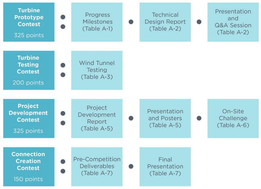
Table of Contents
Revision History .......................................................................................................................v
1 Introduction........................................................................................................................1
 1.1 Background..................................................................................................................1
2 Competition, Contests, Products, and Awards ......................................................................1
 2.1 Overview of Product Submission Deadlines ......................................................................1
 2.2 Awards........................................................................................................................2
3 Turbine Prototype Contest...................................................................................................4
 3.1 Turbine and Load Design Requirements ...........................................................................4
 3.2 Midyear Project Milestones ..........................................................................................11
 3.3 Technical Design Report ..............................................................................................13
 3.4 Presentation and Q&A Session......................................................................................14
4 Turbine Testing Contest ....................................................................................................16
 4.1 Cut-In Wind Speed Task ..............................................................................................17
 4.2 Power Curve Performance Task.....................................................................................18
 4.3 Control of Rated Power and Rotor Speed Task.................................................................18
 4.4 Safety Task ................................................................................................................18
 4.5 Durability Task...........................................................................................................19
5 Project Development Contest.............................................................................................20
 5.1 Part A: Research and Develop a Plan for a 100-MW Wind Farm in Western South Dakota..... 20
 5.2 Part B: Design a Wind Farm During the Competition........................................................23
6 Connection Creation Contest.............................................................................................25
 6.1 Contest Elements ........................................................................................................25
 6.2 Final Presentation and Q&A .........................................................................................28
Glossary.................................................................................................................................29
Appendix A. Rubrics ...............................................................................................................30
 Turbine Prototype Contest....................................................................................................30
 Turbine Testing Contest.......................................................................................................31
 Project Development Contest................................................................................................34
 Connection Creation Contest ................................................................................................35
Appendix B. Sample Safety and Technical Inspection ...............................................................36
Appendix C. Roles and Responsibilities ...................................................................................37
Appendix D. Logistics .............................................................................................................40
 Event Schedule...................................................................................................................40
 Event Registration...............................................................................................................40
 Lodging.............................................................................................................................40
 Local Resources..................................................................................................................40
 Team Booths......................................................................................................................41
 Shipping............................................................................................................................41
 Storing Items at the Event ....................................................................................................41
 Feedback ...........................................................................................................................41
Appendix E. Safety and Conduct..............................................................................................42
Appendix F. Dispute Resolution...............................................................................................45
Appendix G. Communications and Contest Details ...................................................................46
 External Communications ....................................................................................................46
 Internal Communications .....................................................................................................46
 Branding............................................................................................................................46
 Confidentiality and Intellectual Property.................................................................................47
 Judging and Scoring............................................................................................................47
 Submittals and Submission Locations.....................................................................................48
 Written Report Formatting Requirements................................................................................48

 iii

 This report is available at no cost from the National Renewable Energy Laboratory at https://energy.gov/cwc-rules-
 requirements
Audio Visual Presentation Requirements................................................................................49
 Electronic File-Naming Instructions.......................................................................................49
Appendix H. Alternative Competition Structure.........................................................................51
 Background........................................................................................................................51
 Competition, Contests, Products, and Awards..........................................................................51
 Turbine Digital Design Contest.............................................................................................53
 Turbine Testing Contespht....................................................................................................53
 Project Development Contest................................................................................................53
 Connection Creation Contest ................................................................................................53
 Rubrics..............................................................................................................................53
 Logistics............................................................................................................................54
 Dispute Resolution..............................................................................................................54
 Communications and Contest Details.....................................................................................55
Appendix I. Virtual Conference Participation Etiquette...............................................................56

List of Figures
Figure 1. Contests and products overview. Further information available on the point breakdown
 available in Appendix A. Rubrics. .........................................................................................1
Figure 2. Allowable turbine volume ............................................................................................5
Figure 3. Base flange dimensions for turbine attachment to tunnel (dimensions in cm).................6
Figure 4. Load, turbine, storage element, and point of common coupling arrangement..................7
Figure 5. Wiring layout of PCC and student load display table .....................................................8
Figure 6. Proper Anderson Powerpole polarity to match tunnel wiring..........................................9
Figure 7. Team-provided connection to the manual shutdown interface......................................10
Figure 8. Competition-provided connector for manual shutdown interface .................................10
Figure 9. Collegiate Wind Competition wind tunnel basic configuration......................................11
Figure 10. Map of South Dakota ...............................................................................................22
Figure A-1. Score weighting based on power ratio for control of rated power task ...................... 32
Figure A-2. Score weighting based on rpm ratio for control of rated rotor speed task.................. 33
Figure H-1. Updated contest and product overview ...................................................................51

List of Tables
Table 1. Product Deadlines........................................................................................................2
Table A-1. Scoring Rubric for the Midyear Progress Milestones (75 Points Total)*....................... 30
Table A-2. Scoring Rubric for the Technical Design Report and Q&A (250 Points Total)*, **.......... 30
Table A-3. Scoring Rubric for Turbine Performance Testing (200 Points Total)............................31
Table A-4. Weighting for the Power Curve Performance Task.....................................................31
Table A-5. Project Development Contest Part A: Develop Plan for 100-Megawatt Wind Farm (250
 Points Total)*, ** ................................................................................................................34
Table A-6. Project Development Contest Part B: On-Site Design Challenge (75 Points Total) ....... 35
Table A-7. Scoring Rubric for Connection Creation Contest Deliverables (150 Points Total)* ....... 35
Table B-1. Sample Inspection Sheet for Evaluating Test Turbines ..............................................36
Table C-1. Roles and Responsibilities.......................................................................................37
Table E-1. Suggested Hazards and Controls for Testing Prototype Wind Turbines ...................... 43
Table G-1. Team Names and Abbreviations...............................................................................50
Table G-2. Product Names and Abbreviations...........................................................................50
Table H-1. Updated Submission Timelines................................................................................52

 iv

 This report is available at no cost from the National Renewable Energy Laboratory at https://energy.gov/cwc-rules-
 requirements
Revision History
This is the original version, issued October 09, 2020.

 v

This document is available at no cost from the U.S. Department of Energy at. https://energy.gov/cwc-rules-
requirements.
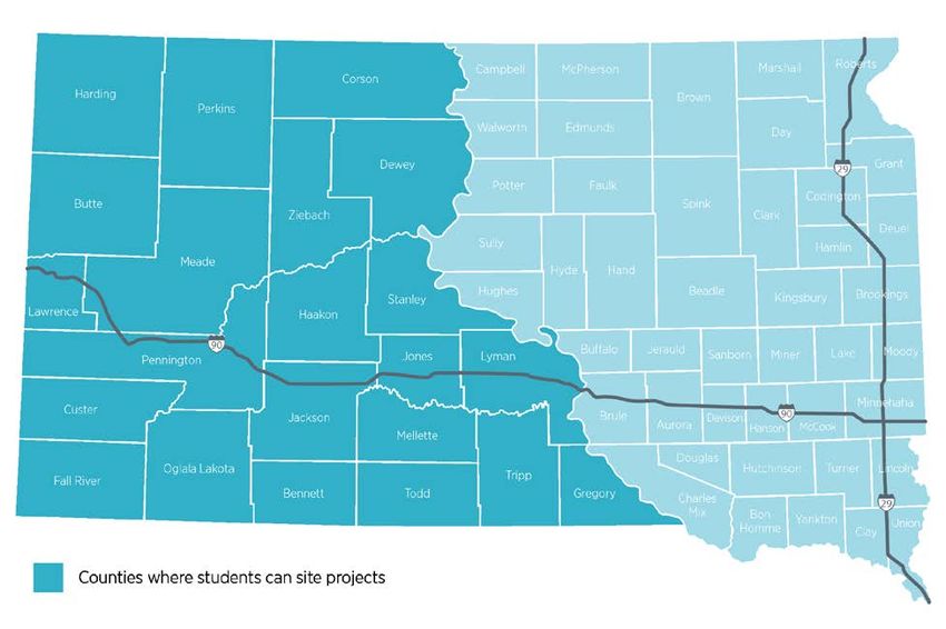
1 Introduction
1.1 Background
According to the U.S. Department of Energy’s (DOE’s) Wind Vision report, wind energy could
supply 20% of the nation’s electricity by 2030 and 35% by 2035.1 As more wind energy is
incorporated into the U.S. power generation mix, qualified workers are needed to fill related jobs
at all levels.

To help facilitate this process, DOE and the National Renewable Energy Laboratory (NREL)
created the Collegiate Wind Competition in 2014 (hereafter referred to as the Collegiate Wind
Competition, CWC, or competition). The competition contributes to the creation and
maintenance of American leadership in the transition to a global clean energy economy.
Specifically, the competition’s objective is to prepare students from multiple disciplines to enter
the wind energy workforce by providing real-world technology experience. Positions in the
workforce that require development include researchers, scientists, engineers, educators, project
managers, and business and sales forces. Wind-energy-specific advanced degrees are not
required for many of these jobs but having wind-related experience is considered to be highly
valuable. 2

Each year, the competition identifies a new challenge and set of activities that address real-world
research questions, thus demonstrating skills that students will need to work in the wind or wider
energy industry. The Collegiate Wind Competition 2021 challenge is to:

 Research, design, and build a turbine for deployment in highly uncertain
 times (with a great degree of unknown risks and delays).

Specifically, competition participants will need to create:

 • An effective mechanical, electrical, and aerodynamic wind turbine and load design that is
 safe and reliable for testing in an on-site wind tunnel.
 • A site plan and cost of energy analysis for a 100-megawatt (MW) wind farm.
 • A presentation on wind energy careers, community engagement, and outreach.
The competition does not prescribe a power system market or wind regime.

Planning projects in the face of uncertainty teaches us the importance of active risk management
and ensures that we understand the probability of occurrence and the consequences. The theme
this year requires teams to take risks into account to the extent possible in the schedule and
budget, for example, to ensure project success. Proactive risk management is fundamental for
any line of employment—a critical skill the organizing team is fortifying alongside the teams this
year. The rules are written to ensure maximum learning in the event of a final in-person or virtual
competition.

1
 http://www.energy.gov/eere/wind/maps/wind-vision
2
 https://www.nrel.gov/docs/fy19osti/73908.pdf
 1

This document is available at no cost from the U.S. Department of Energy at. https://energy.gov/cwc-rules-
requirements.
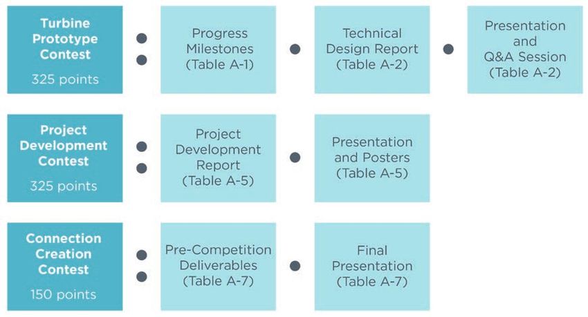
2 Competition, Contests, Products, and Awards
The Collegiate Wind Competition 2021 consists of all the aspects and activities leading up to,
during, and following the event. It includes the subcontract project agreement between the
competitively selected collegiate teams and NREL, as well as the contests, products, and event.

During the event, teams compete in four contests: the Project Development contest, the Turbine
Prototype contest, the Turbine Testing contest, and the Connection Creation contest. Within each
contest, teams’ submissions (hereafter referred to as products) receive points toward winning the
contest. An overview of which product contributes to the scoring of each of the contests is in
Figure 1. How many points a product contributes to the overall score is covered in Appendix A.

Figure 1. Contests and products overview. Further information available on the point breakdown
 available in Appendix A. Rubrics.

2.1 Overview of Product Submission Deadlines
This section gives an overview of when products should be delivered. The competition will run
from Monday, June 7, through Thursday, June 10, 2021, at the American Wind Energy
Association (AWEA) CLEANPOWER Conference in Indianapolis, Indiana. As stated, this rules
document is written to ensure that learning will occur in the event that the in-person competition

 1

This document is available at no cost from the U.S. Department of Energy at. https://energy.gov/cwc-rules-
requirements.
must become virtual. See Appendix H. Alternative Competition Structure for more details. Refer
to each product section and H for format requirements and submission instructions.

 Table 1. Product Deadlines
 Product Submission Deadline

 PRIOR TO COMPETITION:

 Initial list of wind industry contacts Sunday October 4, 2020, 11:59 p.m. MT

 Conceptual design milestone Sunday November 1, 2020, 11:59 p.m. MT

 Distributed manufacturing plan milestone Sunday December 6, 2020, 11:59 p.m. MT

 Outreach plan and team story Sunday January 10, 2021, 11:59 p.m. MT

 Subsystem assembly and testing milestone Sunday April 4, 2021, 11:59 p.m. MT

 Project development report Sunday May 23, 20/21, 11:59 p.m. MT

 Turbine design report Sunday May 23, 2021, 11:59 p.m. MT

 DURING COMPETITION:

 Project development poster(s) (digital) Bring to presentation

 Turbine design question and answer (Q&A) Bring to presentation
 supporting materials (optional)

 Test turbine and load system During safety inspection

2.2 Awards
Awards will include, but not necessarily be limited to, the following:

 • First place winner—the team that earns the highest combined score
 • Second place winner—the team that earns the second-highest combined score
 • Third place winner—the team that earns the third-highest combined score
 • Turbine Prototype contest winner—the team that earns the highest combined score from
 all design products
 • Turbine Testing contest winner—the team that earns the highest combined score from all
 turbine testing products
 • Project Development contest winner—the team that earns the highest combined score
 from all project development products

 2

This document is available at no cost from the U.S. Department of Energy at. https://energy.gov/cwc-rules-
requirements.
• Connection Creation contest winner—the team that earns the highest combined score
 from all industry and community engagement products.

 3

This document is available at no cost from the U.S. Department of Energy at. https://energy.gov/cwc-rules-
requirements.
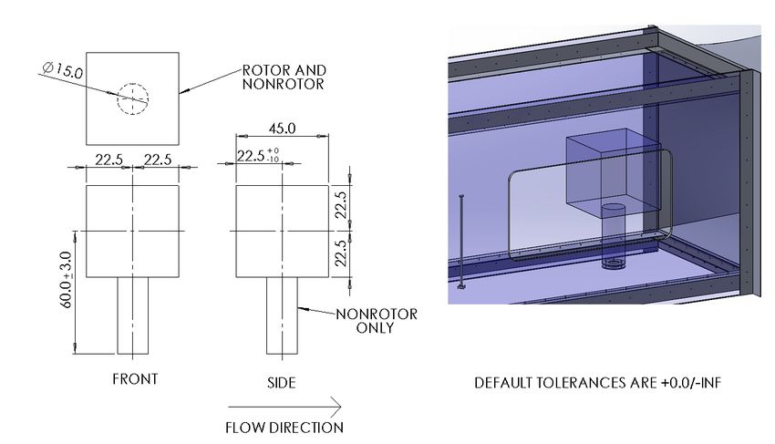
3 Turbine Prototype Contest
The Turbine Prototype contest will comprise three basic components: a series of midyear
milestones, a technical design report, and a prototype turbine. Additionally, at the competition,
teams will present their design to a panel of technical judges who will then conduct a brief
turbine design question and answer (Q&A) session to clarify any questions they have after
reading the reports before finalizing scores. This section will describe the requirements for
turbine design and the details of each of the contest elements. Detailed scoring algorithms and
rubrics can be found in Appendix A.

3.1 Turbine and Load Design Requirements
Each team will design and build a prototype wind turbine. The turbine must be designed, and
loads analyzed to withstand continuous winds of up to 22 meters per second (m/s) but no testing
will be done beyond 13 m/s. Each turbine prototype must be designed for testing inside the
Collegiate Wind Competition wind tunnels (further designated as “tunnel[s]” or “wind
tunnel[s]”). The basic wind tunnel configuration is shown at the end of this section.
3.1.1 Physical Design Constraints Within the Tunnel
At zero yaw angle, the entire turbine must fit within the volume specified as follows and shown
in Figure 2. The turbine may have the following maximum geometry:
 • Rotor and nonrotor turbine parts must be contained in a 45 centimeter (cm)-by-45-cm-
 by-45-cm cube. This cube may be shifted as much as 10 cm aft of the yaw table
 centerline when the turbine is aligned with the flow.
 • A 15-cm diameter cylinder centered on the mounting flange extending from the tunnel
 floor to the bottom of the cube can contain only nonrotor turbine parts. For this purpose,
 nonrotor turbine parts will be defined as anything that does not capture energy from the
 moving air, including the mounting flange.
 • All turbines must fit through the turbine door (61 cm by 122 cm) in one assembly with no
 additional assembly occurring inside the tunnel other than attachment to the base flange
 and connection to external electrical components. Electrical connections should not be
 made in the nacelle during installation.

 4

This document is available at no cost from the U.S. Department of Energy at. https://energy.gov/cwc-rules-
requirements.
Figure 2. Allowable turbine volume

The wind turbine system must be mountable on the test stand within the wind tunnel as follows:
 • The turbine base plate must be constructed of material no thicker than 16.1 millimeters. It
 should be designed and constructed with adequate tolerances to smoothly fit over three
 studs where it will be secured to the tunnel base flange with wingnuts. Figure 3 shows the
 bolt pattern and sizing of the flange and the dimension for the hole to allow cables and
 connectors to pass through.
 • Teams are free to apply their engineering judgment to their own base plate design,
 keeping in mind that the turbine base must be designed to withstand the tension of the
 mounting studs when torqued to approximately 50 Newton-meters.
 • The tunnel base flange incorporates a turntable to generate yawed flow. This flange,
 where the turbine is mounted, will be subjected to yaw rates of up to 180° per second
 with a maximum of two full rotations from the initially installed position.

 5

This document is available at no cost from the U.S. Department of Energy at. https://energy.gov/cwc-rules-
requirements.
Figure 3. Base flange dimensions for turbine attachment to tunnel (dimensions in cm)

3.1.2 Physical Design Constraints Outside the Tunnel
Within practical limits, there is no size restriction for components located outside the tunnel.
These components must be incorporated into closed enclosures that are firesafe and meet or
exceed a National Electrical Manufacturers Association (NEMA) Type 1 rating. All components
must be electrically insulated from the enclosures. Teams should also pay careful attention to the
standards for ventilation of these enclosures, which include the following:

 • NEMA 1 characteristics: Enclosures are constructed for indoor use to provide a degree of
 protection for personnel against access to hazardous parts and to provide a degree of
 protection for the equipment inside the enclosure against ingress of solid foreign objects
 (should not be able to insert fingers or tools through the enclosure when closed). It is
 important that the intent of the NEMA 1 rating be preserved once all connectors and/or
 passthrough devices are installed.
 • All cable passthroughs in enclosures must use cable glands or other similar devices that
 provide both strain and chafe protection.
 • Tape is not considered adequate sealing of penetrations or passthroughs in the enclosure.
 • All electrical cables leading from the turbine to the electronic components located outside
 the tunnel must be in cable form (no individual strands) and have connectors. Individual
 strands or bare wires will result in disqualification from testing until remedied. Twisting
 two or more strands together is permissible as long as the resulting multistrand cable has
 a connector on the end. Multistrand cables are encouraged when used in a logical way.
 For example, there could be one cable for all power wires and one cable for all control
 wires.
 • Neither screw terminals nor spade- or fork-type lugs are considered acceptable
 connectors outside of enclosures. Each cable connection from turbine to enclosure should

 6

This document is available at no cost from the U.S. Department of Energy at. https://energy.gov/cwc-rules-
requirements.
employ a quick-attach connector. Ideally, teams should be able to connect all their cables
 in a few seconds.
 • All electrical components shall be mechanically secured to the enclosure.
3.1.3 Electrical Requirements
Figure 4 illustrates the electrical configuration of the prototype turbine, competition data
acquisition system, and point of common coupling (PCC), which is the point of electrical
measurement for the competition.

 Figure 4. Load, turbine, storage element, and point of common coupling arrangement

 • Voltage must be direct current (DC) at the PCC and is required to be at or below 48 volts
 (V) at all times.
 • The turbine base plate shall be tied to earth ground. To prevent overvoltage of the tunnel
 data acquisition system, turbine electrical system ground(s) must be electrically tied to
 this base plate with a 100 kΩ or lower resistance connection.
 • Teams are expected to choose their own generator and design their own turbine and load
 system. Off-the-shelf components may be used, but the turbine and load system should be
 designed and built by the teams. Both components must meet safety requirements
 including, but not limited to, proper wiring practices, shielding of hazardous components,
 and proper heat rejection.
 • The turbine electronics must be in a separate enclosure(s) from the load to clearly
 differentiate load and control during inspection by judges, as shown in Figure 4. The
 turbine nacelle may also contain turbine electronics, if desired.
3.1.4 Specifications for the Turbine Side of the PCC
 • Energy storage elements, such as capacitors and/or inductors, may be used in both the
 turbine and the load but not for bulk energy storage on the turbine side of the PCC.

 7

This document is available at no cost from the U.S. Department of Energy at. https://energy.gov/cwc-rules-
requirements.
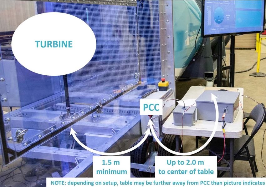
• No batteries of any type or capacitors or combinations of capacitors with nameplate
 voltage and capacitance ratings corresponding to over 10 joules (J) of energy storage (E =
 ½CV2) will be permitted.
 • Turbine components may draw from the load but must register a zero state of charge at
 the beginning of the test.
 • Wired connections between the turbine and load external of the PCC are allowed but
 must be optically isolated.
3.1.5 Specifications for the Load Side of the PCC
 • Bulk energy storage is allowed, provided it is utilized in a safe and reliable manner.
 • To run the load, 120 VAC will be provided, if desired.
3.1.6 Interfacing with the Competition Data Acquisition System
 • Wires should exit the tunnel at the turbine base through the center of the turntable. As
 shown in Figure 5, a table will be provided to display the load on the student side of the
 tunnel and hold any turbine electronics enclosures external of the tunnel. Rough distances
 are shown in the figure, but teams should provide adequate lengths of wire to run from
 the PCC to accommodate their desired enclosure arrangement on the table.

 Figure 5. Wiring layout of PCC and student load display table

 8

This document is available at no cost from the U.S. Department of Energy at. https://energy.gov/cwc-rules-
requirements.
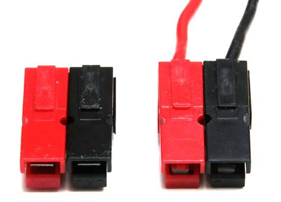
• To interface with the PCC, wires should be terminated with Anderson Powerpole
 connectors, PP15-45 (a red and a black, for positive and negative, respectively). See
 Figure 6 for correct polarity. Incorrect polarity must be corrected before testing.
 • Teams are expected to provide their own Powerpole connectors of an appropriate size: 15
 ampere (A), 30 A, or 45 A, which are specified to handle wire gauges from 10 American
 wire gauge (AWG) through 20 AWG. Each team can choose the wire size it wants to use
 in this range as long as the appropriate current-carrying capacities are taken into
 consideration. All three pin sizes fit into the same housing (PP15-45), as stated earlier.

 Figure 6. Proper Anderson Powerpole polarity to match tunnel wiring
 • Turbines must be capable of shutting down on command through an emergency stop
 button as well as when electrically disconnected from the load.
 o The emergency stop switch will be located outside the tunnel. It operates in the
 same manner as an industrial emergency stop chain. That is, it is closed during
 normal turbine operation and is opened during an emergency stop when the button
 is depressed.
 ̶ In industry, emergency stop systems use this switch polarity so that
 multiple switches in and around a piece of hardware, such as a wind
 turbine, can be wired in series in a single wiring loop. In this
 configuration, opening any switch or a fault in the wiring will cause the
 whole circuit to open. Thus, an entire emergency stop system can be
 monitored by a single channel input. If the switches utilized the opposite
 polarity, the system would have to monitor each switch individually.
 o The emergency stop connector and wiring is rated for 3 A and thus is intended to
 carry a low current control signal—not high current power. Teams must describe
 their emergency stop system during safety and tech inspection and explain how
 this design utilizes a signal that can never carry more than the rated 3 A.
 o Each team must provide a cable containing two wires (no smaller than 28 AWG)
 that reaches the PCC, as labeled in Figure 5. This cable must be terminated, prior
 to the competition, with a standard JST RCY female receptacle housing connector
 9

This document is available at no cost from the U.S. Department of Energy at. https://energy.gov/cwc-rules-
requirements.
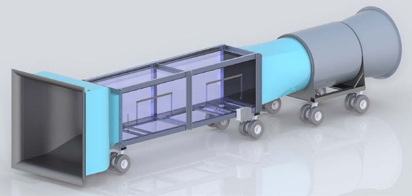
[Manuf. P/N: SYR-02T housing using SYM-001T-P0.6(N) for the corresponding
 male pin contacts]. See Figure 7. 3

 Figure 7. Team-provided connection to the manual shutdown interface
 o The competition switch will be terminated with the corresponding polarity JST
 RCY male plug (Manuf. P/N: SYP-02T-1 plug housing using SYF-001T-
 P0.6[LF][SN]) socket contacts]. See Figure 8.3

 Figure 8. Competition-provided connector for manual shutdown interface

3.1.7 Specifications for Competition Tunnel
A digital rendering of the competition tunnel is shown in Figure 9. The dimensions of the test
chamber are 122 cm by 122 cm by 244 cm. There are inlet and outlet components of the wind
tunnel that extend beyond the test chamber. The tunnel has a drawdown configuration. That is,
the air is sucked through the test section—entering at the left, exiting at the right—with the
drawdown being induced by the fan on the right side of the tunnel. A honeycomb flow
straightener at the inlet of the wind tunnel provides for near-uniform mixing of the incoming air.
There is a debris filter upstream of the fan section. The screen comprises wire mesh to prevent
turbine pieces from getting sucked into the fan unit.

3
 Note: In the remote-control aircraft community, these connector pairs are commonly referred to as JST BEC
connectors and are available from a variety of sources, including Digi-Key.

 10

This document is available at no cost from the U.S. Department of Energy at. https://energy.gov/cwc-rules-
requirements.
Figure 9. Collegiate Wind Competition wind tunnel basic configuration

3.1.8 Safety Specifications
Competition staff will perform a safety inspection of the wind turbine and load system, which
must be passed before they are installed in the wind tunnel.
Appendix B contains a draft version of the safety and inspection sheet used to evaluate the
turbines. The turbine safety officials make the final and official determination about whether a
turbine may be tested in the wind tunnel.

3.2 Midyear Project Milestones
The competition will include a series of scored, midyear milestones to monitor the student
teams’ progress leading up to the final event and incentivize key aspects of the design.
Milestones are scored based on quality of content delivered with details given in each of the
following subsections. Writeups should follow the same formatting requirements as the reports,
detailed in Appendix G. Each section lists page limits, restrictions on length of video that can be
submitted (where relevant), and number of supplemental images (where relevant) that will be
accepted for each milestone. Anything beyond the limits will not be considered during scoring.

3.2.1 Conceptual Design
A crucial part of designing and building any new system is having a viable concept that will
meet the needs of the task. Finding such a concept involves a deep understanding of the task to
be accomplished and the physics of accomplishing that task. Brainstorming, high-level trade
studies, and other methods can be used to narrow in on a concept that could be viable at this
early stage. However, during the rest of the design process, additional challenges may be
identified that require further adaptation.

Deliverables and Scoring:

 11

This document is available at no cost from the U.S. Department of Energy at. https://energy.gov/cwc-rules-
requirements.
• Submit a two-page write-up plus up to five images that describe the concept the team has
 settled on during the conceptual design process. The write-up must explain the basic
 operation of all the major subsystems of the design, how they work together to
 accomplish the task, and why these methods were chosen. However, the teams are
 reminded that this is a conceptual design; details of the design are not needed at this
 stage.
 • Scoring will be based on how clear the concept is articulated, how likely it is to work
 well for the tasks presented, and how well the team articulates their understanding of the
 task and the physics of the problem.

3.2.2 Distributed Manufacturing Plan
In the modern world, it is common for design and manufacturing to be distributed around the
country or even the world. Systems may be designed in different places and parts manufactured
in different facilities, and design often occurs at separate locations from manufacturing.
Ultimately, everything may come together in a single assembly factory (such as with cars or
aircraft) or final assembly may not occur until installation at the field site (such as with wind
turbines).

Given the current uncertainty around in-person meetings and access to shared laboratory space,
developing a cohesive design and manufacturing plan while working collaboratively with team
members in other locations is a valuable experience for team members moving into the
employment market. Furthermore, as we have seen with recent interruptions to the supply chain,
having backup plans is crucial when circumstances prevent normal operations.4

Deliverables and Scoring:

 • Submit a two-page write-up plus up to 10 images that:
 1. Details how the team plans to design the turbine systems whether or not the team is
 able to be co-located. This process should include design for distributed
 manufacturing and should take a strong look at where precision tooling, complex
 processes, instrumentation, and test apparatus are needed and ways to design for less
 critical requirements. Should backups not be feasible, teams must include discussion
 on how they have derisked that portion of the design as much as possible.
 2. Further, a conceptual-level distributed manufacturing and testing plan, including
 backups and potential timeline impacts, should be outlined. The teams are encouraged
 to think about ways to obtain or manufacture and assemble the needed parts with
 limited or no access to well-equipped labs, laboratory personnel, or even to each other
 and to explain that thinking in the report. Outsourcing subcomponent manufacturing
 may be incorporated, but details on how the identified vendor is managing risk should
 also be included.

4
 The organizers have come up with a way to design, construct, and test a competitive turbine in separate
garages/basements/workshops without any direct contact with each other using nothing but low-precision tooling
from local hardware stores and components readily available locally or via mail order.
 12

This document is available at no cost from the U.S. Department of Energy at. https://energy.gov/cwc-rules-
requirements.
• Scores will be based on the thoroughness of the thought processes articulated for the plan
 and how well it is likely to work in an uncertain environment.

3.2.3 Subsystem Assembly and Testing
As in the previous milestone, teams are encouraged to develop a robust and redundant method to
assemble and test their turbine in a distributed environment. Teams should divide up the process
of building the turbine into its subsystems and acquire or construct the parts to assemble those
subsystems. Good design, even when combined with good manufacturing, does not guarantee
working systems. Each subsystem should then be tested before assembly of the complete turbine
begins.

Deliverables and Scoring:

 • Submit a three-page write-up (simple or outline form) plus up to 20 images and optional
 video up to 3 minutes long that describes how each of the critical subassemblies was
 assembled and tested. The teams are encouraged to define what and how many
 subsystems are critical for their design. Two examples might be the system that converts
 the kinetic energy of the wind into mechanical energy and the system that converts that
 mechanical energy into electrical energy.
 • Scores will be based on how well the teams identify critical subassemblies, how well they
 were tested, and how the assembly and testing process was outlined in the milestone
 writeup. Scores will not be based on how well the subsystems performed during the
 testing. A failure found during testing is every bit as valuable as a success.

3.3 Technical Design Report
The technical design report explains the turbine concept development process from an
engineering perspective. The design report should detail the complete design process as it relates
to the turbine being tested in the competition wind tunnel. Teams should provide detail that is
adequate for an engineering review of the baseline and operating properties of the turbine and its
subsystems, including mechanical loading requirements, operational limits, control algorithms,
and software. At a minimum, the following topics should be included:

 • A description of the design objective and how the design components support this
 objective.
 • A basic static performance analysis (e.g., CP-Lambda report) of the turbine design that
 contains the annual energy production over a range of operational parameters.
 • An analysis of the expected mechanical loads and associated safety factors within the
 design, both for operational and parked conditions.
 • A description and analysis of the turbine’s yaw system (if included).
 • An electrical analysis comprised of the generator model, power electronics (e.g.,
 canonical model and one-line diagram), electrical load model, and operating voltage
 including how the team plans to regulate voltage.

 13

This document is available at no cost from the U.S. Department of Energy at. https://energy.gov/cwc-rules-
requirements.
• A control model analysis of the operational modes (i.e., the control states diagram and a
 description of primary operational modes).
 • Documentation of associated software architecture (e.g., data acquisition, turbine control,
 safety systems, states and state diagram, outputs to the turbine actuators, and data
 archiving) and its development. Note that this is about the development of the software
 itself, not the turbine control methodologies that were described earlier.
 • A description of the final assembly of the turbine’s subsystems. Where relevant, include
 how a distributed team environment was managed.
 • A commissioning checklist that can be followed during installation of the turbine in the
 wind tunnel allowing no steps to be forgotten or executed in the wrong order.
 • The results of laboratory and/or field testing of turbine prototypes.
 • Engineering diagrams with at least a basic mechanical drawing of all components and an
 electrical one-line diagram.
 • New for 2021: A clear and concise enumeration of what is the same as previous years
 and why. Demonstrate an understanding of how previous research and design decisions
 have shaped the team’s decisions. If a team’s school did not compete in the previous
 year’s competition, they should write a few sentences about how the information in last
 year’s winning design report influenced their own design.
At a minimum, the report must include the following sections:
 • Cover sheet. Teams should begin the report with a one-page cover sheet that includes
 their affiliation and contact information. Indicate the team roles/hierarchy and
 approximately how many students, faculty, and others (e.g., sponsors, volunteers, and
 family members) are involved in the project.
 • Table of contents
 • Executive summary. The executive summary discusses components from all sections of
 the report and includes a short description of the team project. Teams should use their
 judgment when deciding how long to make the executive summary; however, one page is
 often sufficient.
 • Technical design.
The technical design report should not exceed 20 pages in length. Pages submitted beyond this
limit will not be reviewed. The cover sheet and references are not required to fit within the page
limit, but a table of contents and appendices are.
Scoring criteria for the design report is provided in Appendix A. Report formatting requirements
are provided in Appendix G. At the conclusion of the competition, team reports will be posted to
the competition website for reference during future events.

3.4 Presentation and Q&A Session
In addition to the written report, each team will present their design to a panel of judges followed
by a Q&A to answer any remaining questions that the judges may have from their review of the
written report. This presentation should begin with a brief overview that conveys the most
 14

This document is available at no cost from the U.S. Department of Energy at. https://energy.gov/cwc-rules-
requirements.
important details of the technical design, clearly communicating the team’s approach to design
and development.

Presenters should showcase their turbine prototype and have the option to use posters, charts,
PowerPoint slides, or other visual aids to engage with the judges. Please note visual aids will not
be scored but can be used if necessary, to help clarify any questions the judges may have after
reading the written report. Please bring necessary files on a USB drive along with any drivers
needed to support presentation animation. Presentations are limited to 10 minutes, which will be
followed by a 15-minute Q&A period with the competition judges. Additional attendees are
allowed in the feedback session at the discretion of the students and their principal investigator.

The judges will use the content from this project overview and Q&A period to make final
adjustments to the technical design report score. Answers provided during the Q&A session will
also be evaluated to gauge the depth of students’ technical understanding of turbine design, as
shown in Table A-2.

 15

This document is available at no cost from the U.S. Department of Energy at. https://energy.gov/cwc-rules-
requirements.
4 Turbine Testing Contest
The Turbine Testing contest comprises several individual turbine tasks. This section describes
the requirements of the individual tasks in which the turbine is expected to perform and the
parameters of the testing conditions. Details on scoring algorithms and point allocations between
individual tasks can be found in Appendix A.

Testing provides teams with the opportunity to demonstrate their turbine’s performance through
objective tasks—and the testing outcomes help determine if they have succeeded in developing a
durable, safe, high-performing machine (performance is a strong indicator of a turbine’s ability
to compete successfully in the marketplace).

Each turbine, along with its corresponding load system, will be tested in the competition wind
tunnel. The contest will include the following tasks: turbine performance, turbine-rated
revolutions per minute (rpm) and power control, cut-in wind speed, turbine durability over a
range of wind speeds and yaw positions, and turbine safety. Students will use their load for all
tasks. While the prescribed order will be the same for each team, the exact amount of time at
each setpoint could vary between schools. Thus, teams are expected to design their turbines to
sense the local conditions within the tunnel and react accordingly for each task.

Exceeding the voltage limit set in Section 3.1.3 will result in an immediate abort of the testing
sequence with all points gathered to that point retained but no more points earned after the abort.
Teams may then attempt to fix the cause of the overvoltage and use their retest if available. 5,6

Verification of zero energy at the start of the test will be accomplished using the competition
data acquisition system to measure zero current flow into the load at the PCC. Any questionable
elements are subject to additional verification of zero energy by the testing team with a
multimeter or similar device before the testing begins.

All wind tunnel testing tasks at competition will be optional. The teams will be able to choose
if they want to design to accomplish all the tasks or a reduced set. Note that teams must attempt
at least one task. Teams that are newer to the competition, teams with fewer returning members,
and teams who are feeling behind schedule are encouraged to focus on fewer tasks. Teams may
find it strategic to focus their efforts and maximize their points on a subset of tasks instead of
spreading themselves too thin. Additionally, since each team will be tested in the same sequence
in the wind tunnel, opting out of a task will allow a team to effectively skip over one that could
have catastrophic effects on their system in order to score additional points on the later tasks.
There is no penalty for opting out of a task beyond losing the points for that task. All teams will
be ranked solely based on points and not on which teams attempted more tasks.

When installing the turbine in the tunnel, a team representative should be prepared to identify to
the judges which tasks, if any, the team chooses to opt out of. If desired, teams may choose a
different selection of tasks during their retest.

5 https://www.osha.gov/pls/oshaweb/owadisp.show_document?p_id=9880&p_table=STANDARDS
6
 https://www.mouser.com/pdfdocs/Why-are-Power-Designs-Moving-to-48V.pdf
 16

This document is available at no cost from the U.S. Department of Energy at. https://energy.gov/cwc-rules-
requirements.
Only one team’s turbine will be tested at a time. Teams are limited to 10 members (students and
principal investigators) within the testing area. Other members can act as spectators. Each team
will have 35 minutes of tunnel time to install their turbine, commission it, test it, and uninstall.
Teams will be provided with a period of commissioning time prior to the scoring tasks, during
which the teams may ask for any wind speed from 5 m/s to 11 m/s and do any work on their
turbine or electronics they deem necessary to get their systems up and running. Teams may use
as much of their tunnel time for commissioning as they would like, keeping in mind that the
testing tasks will be stopped promptly 5 minutes prior to the end of the team’s allotted period to
allow time to remove the turbine. Students are encouraged to minimize install and
commissioning time as much as possible because the complete series of testing tasks are
expected to require upward of 20 minutes to complete, depending on how fast the turbine
stabilizes during certain testing conditions.

Additionally, teams may signal at any time during the test that they would like to turn the session
into a practice session. In this case, the score for this attempt will be zeroed, and the team can use
their remaining time to troubleshoot and learn about their turbine’s performance in preparation
for an additional session, if they have one available.

If there are unforeseen delays caused by the organizers (e.g., a wind tunnel issue or power
outage), the time spent rectifying the problem will not be included as part of the team’s
allowable minutes. Team members will only be allowed to touch their turbines or controls during
the following phases of testing: commissioning, to manually restart their turbine if they fail to
restart after a safety shutdown task, and at the start of the durability task. Turbine failure is
defined as anything out of the ordinary, such as cracking, breaking, pieces falling off, smoking,
sparking, or failure to produce an electrical current, and will be cause for immediate stoppage
of testing.

If a team wants to retest their turbine for any reason, team members may request a single retest
during the provided makeup sessions later in the competition. The retest will be a full test, and
all scores from the first test will be replaced, regardless of the turbine’s performance in the retest.

Students are encouraged to bring spare components and/or assemblies and to design their
turbines so that damaged parts or assemblies can be easily replaced. However, it is important to
keep in mind that the turbine configuration throughout the entire competition should remain
substantially the same as what is documented in the written report. For example, the number of
blades, rotor axis, turbine configuration, and operating voltage must remain the same. Teams
with questions about any changes or altered turbine components or assemblies are encouraged to
discuss their particular situation with the organizers well ahead of the competition to ensure they
are adhering to this requirement.

4.1 Cut-In Wind Speed Task
Cut-in wind speed—the lowest wind speed at which a turbine produces power—is one of the
characteristics that can differentiate one turbine as being better suited to lower wind-speed
regimes than others. Lower wind speed is generally deemed more desirable in the small turbine
market.

 17

This document is available at no cost from the U.S. Department of Energy at. https://energy.gov/cwc-rules-
requirements.
In this task, each turbine will be subjected to slowly increasing wind speeds, from 2.5 m/s to
5 m/s, to determine the cut-in wind speed. For this task, “producing power” is defined as
achieving a positive current average over a 5-second interval at a steady wind speed.

4.2 Power Curve Performance Task
The objective of this task is to test each turbine over a range of wind speeds to determine a
power curve. It is meant to be a direct comparison of power performance between turbines,
which is one factor by which real turbines are judged.

Each turbine will be tested at integer wind speeds between 5 m/s and 11 m/s inclusive for a
duration of 60 seconds or less, with the stated intent of obtaining a “stable” power reading, which
is defined as stable rpm and power per electronic testing device during the test period. As power
output may fluctuate, for the purposes of this task, the allowable power outputs to be included in
the maximum average power (per electronic testing device) during any 5-second interval will be
defined as +/-10% of the maximum average power.

This stability criterion will also consider any noise that the data acquisition system measures.
The system samples at 50 kilohertz (kHz) with a filter with a cutoff frequency of 22.5 kHz.
These samples are then block-averaged down to 200 Hz. In order to meet the specified stability
tolerance, teams should ensure that any noise in the power their turbine produces is adequately
filtered and ensure that the combination of power variation and measured noise is within the
specified tolerance when read by the competition data acquisition system. One way to reduce
noise is to implement an LC filter on the power output lines to filter noise coming from the
switching of the power electronics.

4.3 Control of Rated Power and Rotor Speed Task
Wind turbines must withstand high winds without damage to their mechanical or electrical
components. Because wind power is proportional to the cube of wind speed, the energy available
in the wind quickly becomes very high as wind speed increases. To control rising mechanical
and electrical loads, turbines must be able to limit their rotational speed and output power in
these high-wind conditions.

In this task, each turbine will be subjected to two wind speed bins at 12 m/s and 13 m/s. Turbine
performance in those two bins will be compared to the performance in the 11-m/s bin. The
turbines are expected to keep the rpm at or below the rpm determined at 11 m/s and to keep the
power at the same level as is determined at 11 m/s. The stability criterion defined in Section 4.2
will be applied to speed and power in this task.

4.4 Safety Task
Safety is of the utmost importance to turbine designers and manufacturers. To be certified,
turbines must be able to safely shut down rapidly and with a fail-safe shutdown capability.
Turbines must shut down when disconnected from the grid as well as manually upon command,
as described in Section 3.1. Each team may choose to address these shutdown scenarios with one
or two systems or mechanisms.

 18

This document is available at no cost from the U.S. Department of Energy at. https://energy.gov/cwc-rules-
requirements.
In this task, the turbine will be required to safely shut down at two different times during the
testing period at any wind speed—up to the maximum continuous operational wind speed
specified in Section 3.1. For each turbine, the shutdown process will be initiated once “on
command” and separately by disconnecting the load from the PCC. It is important that the load is
disconnected from the PCC and not the turbine to ensure that the competition data acquisition
system can continue to monitor the open circuit voltage of the wind turbine, which must not
exceed the limit provided in Section 3.1. The turbine must also be capable of restarting at any
wind speed above 5 m/s. For the purposes of this task, “shutdown” is defined as dropping below
10% of the maximum 5-second bin average rpm achieved during power performance testing.
This reduction in rpm must occur within 10 seconds and remain below the limit indefinitely. If
the turbine fails to successfully restart, the team may work on their electronics to manually
restart their turbine, resulting in a zero score for the restart portion of the task.

4.5 Durability Task
Turbines are expected to perform over the long term and will be subjected to a wide variety of
weather conditions. Producing power effectively and over the course of the turbine’s lifetime are
desirable design qualities.

In this task, each turbine will be subjected to the same prescribed variable wind speed and
direction function. Speeds will never be less than 6 m/s or greater than 13 m/s during a 5-minute
test period. Yawed flow will be achieved using the tunnel’s turntable governed by the limits set
in Section 3.1. This test helps verify that the turbine can function over a wide range of operating
conditions.

The scoring for this task will be based on the turbine system’s ability to produce positive power
using the student load.

 19

This document is available at no cost from the U.S. Department of Energy at. https://energy.gov/cwc-rules-
requirements.
You can also read