Instruction Manual Care Bed - Lenus - Lenus Care Bed - Burmeier
←
→
Page content transcription
If your browser does not render page correctly, please read the page content below
Instruction Manual
 Lenus
 Care Bed

Lenus Care Bed

 Last updated: 20/01/2021 288242_V1
Instruction Manual for Lenus Care Bed

 1 2 3 4 5

 14 6

 13 12 11 10 9 8 7

 In this instruction manual, numbers and letters that appear in round brackets () and
 bold type refer to the care bed’s operating devices as shown in this and the
 following images.

 1 Foot section chassis
 2 Bars of full-length safety side (DSG)
 3 Handset
 4 Mattress retainer bar (4x)
 5 Head section chassis
 6 Individual axle braking (brake lever version, head end)
 7 Patient lifting pole sleeves (2x)
 8 Guide rails (4x)
 9 Backrest
 10 Side panel (concealed in the picture)
 11 Thigh rest
 12 Lower leg rest
 13 Screw (2x, concealed in the picture), for releasing the bed extension
 14 Individual axle braking (brake bar version, foot end)

Page 2
Instruction Manual for Lenus Care Bed

 Contents
1 FOREWORD ..................................................................................................................... 6
2 GENERAL INFORMATION ............................................................................................... 7
 2.1 Definition of the groups of persons involved ................................................... 8
 2.2 Safety information ........................................................................................... 9
 Explanation of the safety symbols used ................................................. 9
 Safety information for the operator ....................................................... 10
 Safety information for users and residents ........................................... 11
 2.3 Product description ....................................................................................... 13
 Intended use ......................................................................................... 13
 Use for the intended purpose ............................................................... 13
 Contraindications .................................................................................. 14
 Side effects........................................................................................... 14
 Particular features of the bed ............................................................... 14
 Electric drive system............................................................................. 15
 Special electrical features (optional equipment) ................................... 15
 Special mechanical features (optional equipment) ............................... 16
 Materials used ...................................................................................... 16
 Structural design................................................................................... 16
3 ASSEMBLY AND PUTTING INTO SERVICE .................................................................. 17
 3.1 Tools ............................................................................................................. 17
 3.2 Included in the package ................................................................................ 17
 3.3 Location requirements .................................................................................. 18
 3.4 Assembling the mattress base frame ............................................................ 18
 3.5 Assembling the chassis ................................................................................ 19
 3.6 Fitting the side panels ................................................................................... 21
 3.7 Attaching the safety sides ............................................................................. 22
 3.8 Electrical connection ..................................................................................... 24
 3.9 Connecting the power adapter/power plug ................................................... 27
 Power adapter ...................................................................................... 27
 Power plug ........................................................................................... 27
 3.10 Putting into service........................................................................................ 29
 Checklist: Inspection by the user .......................................................... 30
4 OPERATION ................................................................................................................... 31
 4.1 Tips on using the bed safely in a domestic setting ........................................ 31
 4.2 Moving and braking the bed .......................................................................... 32
 Individual axle braking .......................................................................... 33
 4.3 Mechanical adjustment options ..................................................................... 34
 Lower leg rest (LR) ............................................................................... 34
 Manual CPR release of the backrest .................................................... 35
 4.4 Electrical adjustment options ........................................................................ 37
 Special safety information on the electrical drive system ..................... 37
 Handset ................................................................................................ 40
 Handset for Trendelenburg/reverse-Trendelenburg position (optional
 equipment) ........................................................................................... 43
 Handset locking functions ..................................................................... 44
 4.5 Attachments and optional features................................................................ 45
 LED reading lamp* ............................................................................... 45

 Page 3
Instruction Manual for Lenus Care Bed

 Under bed light* ................................................................................... 46
 Rechargeable battery* ......................................................................... 47
 Patient lifting pole* ............................................................................... 48
 Grab handle* (triangular grab handle) ................................................. 49
 Integrated bed extension* .................................................................... 50
 4.6 Operating the safety sides ........................................................................... 52
 Special safety information for safety sides........................................... 53
 Raising the safety sides ....................................................................... 55
 Lowering the safety sides .................................................................... 55
 4.7 Removing/installing the safety sides ............................................................ 57
 Removal .............................................................................................. 57
 Installation ........................................................................................... 57
 4.8 Comfort mattress base, 90 cm wide (optional equipment) ........................... 58
 4.9 Inserting the mattress ................................................................................... 59
5 CLEANING AND DISINFECTION ................................................................................... 60
 5.1 General information on cleaning and disinfection......................................... 60
 5.2 Cleaning and disinfection plan ..................................................................... 61
 5.3 Instructing users and staff ............................................................................ 62
 5.4 Cleaning and disinfection agents ................................................................. 63
 5.5 Handling cleaning and disinfection agents ................................................... 64
6 MAINTENANCE .............................................................................................................. 65
 6.1 By the user ................................................................................................... 66
 6.2 By the operator............................................................................................. 67
 6.3 Replacement parts / Type plate ................................................................... 72
 Type plate ............................................................................................ 72
 PID bar code ........................................................................................ 72
 6.4 Service address ........................................................................................... 73
 6.5 Replacement of electrical components ........................................................ 74
 Plug assignment on the control unit ..................................................... 74
 Replacing the handset ......................................................................... 76
 Replacing the control unit .................................................................... 77
 Initialising the control unit .................................................................... 77
 RESET the control unit ........................................................................ 79
 Replacing the motors ........................................................................... 80
 Decommissioning ................................................................................ 80
7 TROUBLESHOOTING .................................................................................................... 81
8 ACCESSORIES .............................................................................................................. 83
9 TECHNICAL DATA ......................................................................................................... 84
 9.1 Dimensions and weights .............................................................................. 84
 9.2 Adjustment ranges ....................................................................................... 84
 9.3 Electrical data............................................................................................... 85
 9.4 Ambient conditions ....................................................................................... 87
 9.5 Symbols shown on the product .................................................................... 88
 Electrical data ...................................................................................... 88
 Type plate and PID bar code ............................................................... 88
 Stickers ................................................................................................ 89
 9.6 Information on electromagnetic compatibility (EMC) .................................... 90
 9.7 Classification ................................................................................................ 93

 Page 4
Instruction Manual for Lenus Care Bed

10 DISMANTLING THE BED ............................................................................................... 94
11 DISPOSAL INSTRUCTIONS ........................................................................................... 95
12 DECLARATION OF CONFORMITY ................................................................................ 96

 Page 5
Instruction Manual for Lenus Care Bed

1 Foreword

 Dear Customer,
 Burmeier has built this bed to give you the best possible help with the challenges posed
 by nursing and caregiving. We passionately pursue the goal of developing products that
 are durable and of a high-quality. Our products should make residents feel as safe and
 comfortable as possible during their stay in bed and also lighten the workload of care
 staff and caring relatives. For this reason, the electrical safety and all functions are
 tested prior to delivery. Each bed leaves our factory in perfect condition.
 Correct operation and care are necessary to keep the bed in excellent condition during
 long-term use. Please therefore read and observe these instructions carefully. They will
 help you to put the bed into service for the first time and to use it on a daily basis. This
 instruction manual contains all the information you will need to make it as easy and safe
 as possible to control and handle this bed, both for you as the operator and for your
 users. This instruction manual is a practical reference book and should be kept close to
 hand at all times.
 The medical retail trade that delivered this bed is also there to assist you with any
 questions you may have concerning servicing and repairs during the product’s lifetime
 of use.
 This bed is designed to give the person in need of care and all users a safe and
 practical piece of equipment that provides decisive support with the ever-increasing
 requirements of care-giving.
 Thank you for the confidence you have place in us and our products.
 Burmeier GmbH & Co. KG

 You are a medical product retailer and would like to get in touch with Burmeier? Feel
 free to phone us: You can contact our service centre in Germany by phone at +49 (0)
 5232 9841 - 0. Customers outside Germany can contact our distribution companies in
 their respective country if they have any questions. For more information visit:
 www.burmeier.com

 Page 6
Instruction Manual for Lenus Care Bed

2 General information
 The Lenus care bed, hereafter referred to as the bed or the care bed, is
 manufactured in various models. This instruction manual has been issued for
 several bed models. It is possible that certain functions or special features
 are described which your bed does not have.

 Instructions for the operator:
 • This care bed fulfils all the requirements of the Medical Device Regulation (EU)
 2017/745 (MDR). It is classified as a Class I active medical device in accordance
 with § 13 of the German Medical Devices Act (Medizinproduktegesetz: MPG).
 • Please observe your obligations as the operator in accordance with the Medical
 Devices Operator Ordinance (Medizinprodukte-Betreiberverordnung, German
 abbreviation: MPBetreibV), to ensure that this medical product is always operated
 safely and with no risk of danger to patients, users, or third parties.
 • Any item of technical equipment, electrical or otherwise, can prove hazardous if used
 improperly.
 • Read through this instruction manual from start to finish to prevent any injury or
 damage resulting from incorrect operation.
 • Use this bed only as intended by the manufacturer, in accordance with the
 instructions in this manual.
 • You are obliged to instruct users in the proper use of this bed in accordance with
 MPBetreibV (Operators of Medical Products Ordinance) § 5 (see chapter 4).
 • Ensure that users know where this instruction manual is kept, in accordance with the
 Medical Devices Operator Ordinance (MPBetreibV) § 9!

 Instructions for the user:
 • Before using a bed, the user must check that the bed is fully functional and in perfect
 working order, and must observe the instructions in the manual, in accordance with
 the Medical Devices Operator Ordinance (MPBetreibV) § 2. This also applies for
 accessories.
 • Read through this instruction manual from start to finish to prevent any injury or
 damage resulting from incorrect operation.
 • This instruction manual contains safety information which must be followed! All users
 working on and with the Lenus bed model must be familiar with the contents of this
 instruction manual and follow the safety information provided before operating the
 bed for the first time.

 Before using the bed for the first time:
 • Remove all transport securing devices and packaging film.
 • Assemble the bed from the knocked down assembly units in accordance with the
 assembly instructions.
 • Clean and disinfect the bed before using it for the first time.

 Page 7
Instruction Manual for Lenus Care Bed

Features of the bed
The main features of the Lenus bed are listed below:
 Height Safe
 Castor locking
 Model adjustment working Type of castor
 mechanism
 range load

 Lenus Approx. 10.5 - 225 kg 50 mm double Locked in pairs at
 80 cm castor the head/foot end

2.1 DEFINITION OF THE GROUPS OF PERSONS INVOLVED
In this instruction manual, the following groups of persons are defined as:

Operator
The operator (e.g. nursing home operators) are all natural and legal persons with
property rights to the Lenus care bed. The operator is responsible for the safe operation
of this medical device.
The operator can also pass on this responsibility to service providers who work on his
behalf (in Germany, it could be that the health insurance operator passes responsibility
to the medical supply store, for example).

Care staff/Users
Care staff/users are skilled persons who, based on their training, experience or briefing,
are qualified to operate the care bed on their own authority or to carry out work with the
care bed, or have been instructed how to handle the care bed. Furthermore, they are
able to recognise and avoid potential hazards and assess the clinical condition of the
resident.

Residents
In this instruction manual, the term resident is defined as a person who is infirm or in
need of care and occupies this care bed.
When the bed is used in a private, domestic setting, it is strongly recommended that the
operator or his representative instruct each resident on how to use the bed functions
that are important for him/her.

Page 8
Instruction Manual for Lenus Care Bed

2.2 SAFETY INFORMATION
At the time of leaving the factory, this bed represents state-of-the-art technology and
has been tested by an independent testing institute. The most important objective of the
safety information is to prevent personal injuries. Property damage will also be
prevented.
Only use this bed if you are absolutely certain that it is in perfect working order!

2.2.1 Explanation of the safety symbols used
In this instruction manual, the following safety symbols are used:

Risk of injury to persons

 This symbol indicates hazards due to electrical voltages. There is danger
 to life.

 This symbol indicates general hazards. There is danger to life and health.

Risk of damage to property

 This symbol indicates possible damage to property. It is possible that damage
 may occur to the drive, materials or the environment.

Other advice

 This symbol indicates a useful general tip. If you follow it, you will find it easier
 to operate the bed. This tip is provided to give you a better understanding.
Please note:
The safety symbols used are not a substitute for the written safety information. It
is important therefore to read the safety information and follow the instructions
exactly!
All persons who work on or with this bed must be familiar with the contents of
this instruction manual and follow all the safety advice that is relevant for them.

 Page 9
Instruction Manual for Lenus Care Bed

2.2.2 Safety information for the operator
• Please observe your obligations in accordance with the Medical Devices Operator
 Ordinance (Medizinprodukte-Betreiberverordnung: MPBetreibV), to ensure that this
 medical product is always operated safely and with no risk of danger to residents,
 users or third parties.
• Using this instruction manual, which must be provided with the bed, make sure that
 every user and resident is instructed in the safe operation of the bed before using it
 for the first time.
• If the bed is used in a domestic setting, leave your contact details with the resident in
 case they have any questions regarding its use or servicing. (Use the address field
 on the back cover of this manual).
• Draw every user’s attention to the possible hazards that can arise if the bed is
 improperly used. This applies in particular to the use of electrical drives and safety
 sides.
• If the bed is in long-term use, test the functions and check for any visible damage
 (see chapter 6.2) after a reasonable period of time (recommendation: once a year).
• Only persons who have been properly instructed in its use must be allowed to
 operate this bed.
• Check to ensure that the safety instructions are adhered to!
• Make sure that substitute staff are also sufficiently well instructed in the safe
 operation of this bed.
• If any additional devices (such as compressors for positioning systems) are attached,
 ensure that these are securely fastened and are working properly. Pay particular
 attention to:
 o Safe routing of all loose connector cables, tubing etc.
 o Ensuring that no multiple socket outlets are located under the bed (fire hazard due
 to ingressing liquids).
 o Chapter 2.3.2 of this instruction manual

Page 10
Instruction Manual for Lenus Care Bed

2.2.3 Safety information for users and residents
• Ensure that the operator/your medical supply store instructs you in the safe
 operation of this bed.
• Ask a healthcare professional for advice if you are uncertain about a possible
 application of safety sides or about the necessity of activating the locking functions
 of the electrical adjustments.
• Check each time before using the bed to ensure that it is in perfect working order
 (see also chapter 3.10.1). Ensure that no obstacles, such as bedside cabinets,
 supply rails or chairs could impede adjustments to the bed.
• If any additional devices (such as compressors for positioning systems) are
 attached, ensure that these are securely fastened and are working properly. Pay
 particular attention to:
 - Safe routing of all loose connector cables, tubing etc.
 - Do not use multiple socket outlets placed loosely on the floor. These could
 cause electrical hazards due to damaged mains cables or the ingress of liquids.
 If anything is unclear, please contact the manufacturer of the device.
• If any damage or malfunction is suspected, take the bed out of service:
 - Unplug the power adapter from the mains socket immediately.
 - Indicate clearly that the bed is “OUT OF ORDER”.
 - Report this immediately to the operator responsible/your responsible medical
 supply store (see the address on the back cover of this manual).

 • Route the cable of the power adapter, and also all other cables, in
 such a way that they cannot be pulled, driven over or damaged by
 moving parts when the bed is operated.
 • Never leave unsupervised toddlers or babies alone with the bed!
 o There is a strangulation hazard due to the possibility of
 entanglement in exposed connecting cables (such as the
 power cable and handset cable).
 o There is a risk of suffocation from swallowing small parts
 which may have become detached from the bed.
 • Lock the electrical adjustment functions of the bed if their
 unsupervised use could put staff or other persons at risk.
 • The power adapter cable is fitted with a mains cable holder.
 - Before moving the bed, always make sure that you have
 unplugged the power adapter from the mains socket. Hang it
 on the bars of the safety side with the mains cable holder to
 ensure the power adapter will not fall off and the cable does not
 trail on the floor.
 • Do not place multiple socket outlets under the bed. This could cause
 electrical hazards due to damaged mains cables or the ingress of
 fluids.

 Page 11
Instruction Manual for Lenus Care Bed

 • Adjust the mattress base to its lowest position before leaving the
 resident unattended. In this way, you considerably reduce the risk of
 injury to the resident due to a fall when getting in or out of bed.
 • Always ensure that the castor brakes are applied when the bed is
 not being moved.
 • When not in use, stow the handset in such a way that it cannot
 inadvertently fall off (hang it up by the hook). Make sure that the
 cable cannot be damaged by moving parts of the bed.
 • Adjustments must only be performed by, or in the presence of, a
 trained person.
 • Before carrying out any adjustments, make sure that there are no
 people, limbs, pets or objects in the way, in order to avoid
 entrapment hazards and/or damage to property. This applies
 particularly when mattress base sections are adjusted to a lower
 height.
 • To safeguard against unintentional motorised adjustments, lock the
 relevant functions of the handset if:
 - the resident is unable to operate the bed safely or to free
 himself/herself from potentially dangerous situations.
 - the resident could be at risk due to unintentional motorised
 adjustments.
 - The safety sides are raised (danger that the person's limbs could be
 trapped when adjusting the backrest and thigh rest).
 - children are left unsupervised in the room with the bed.
 • Always ensure that the bed is in its lowest position before leaving
 the resident unattended in bed. In this way you can minimise the risk
 of injury should the patient fall out of bed.
 • At regular intervals, carry out a visual inspection of the power
 adapter and cable to check for mechanical damage (scuffing, cracks
 in the housing, exposed wires, kinks, indentations etc.). Perform
 such a check:
 - Whenever the cable has been subjected to any mechanical load,
 e.g. has been driven over by the bed itself or by an equipment
 trolley.
 - Whenever the cable has been bent, stretched or violently pulled,
 e.g. due to the bed rolling away while it is still plugged into the
 switch-mode power supply.
 - Whenever the bed has been moved or relocated and before
 plugging the power adapter back into the mains socket.
 - Regularly, but at least once a week, by the user when the bed is
 in constant use.
 • Check the strain relief of the power adapter cable regularly to ensure
 that it is securely fixed.
 Observe the safety information found in this instruction manual!

Page 12
Instruction Manual for Lenus Care Bed

2.3 PRODUCT DESCRIPTION
2.3.1 Intended use
• This bed is used as an aid in the diagnosis, treatment, alleviation and monitoring of
 illnesses or for compensating for injuries or disabilities.
 For detailed instructions for use, see chapter 9.7
• This bed is suitable only for accommodating adult residents whose height is at least
 146 cm.
• The bed itself is not life sustaining or life supporting.
• The bed has no medical indication.
2.3.2 Use for the intended purpose
• This bed was developed as a comfortable and convenient solution for the support
 and care of infirm persons in need of care in homes for the elderly, nursing homes
 and comparable medical facilities, and for use in the home.
• The use of this bed in hospitals is only permitted in rooms designed for medical
 treatment of the application group 0 (in accordance with VDE 0100 part 710,
 previously VDE 0107). This bed was not designed for any other usage!
• This bed may be intended for care under the supervision of a doctor and be used for
 diagnosis, treatment or observation of the resident. It is therefore equipped with an
 option of locking the handset.
• This bed has no special connectors for potential equalisation. Please pay attention
 to this before connecting additional mains-operated (medical) electrical equipment. If
 necessary, further advice on additional protective measures can be found:
 o in the instruction manuals of these additional mains-operated electrical devices (e.g.
 compressed air positioning systems, infusion pumps, enteral feeding devices ...)
 o in the EN 60601-1-1 standard (Safety of Medical Electrical Equipment)
 o in the VDE 0100 standard Part 710 (High Voltage Installations in Hospitals).
• Please refer to the safety information provided in chapter 4.4.4and 4.6.1, particularly
 where residents are in poor clinical condition.
• This bed is suitable only for accommodating residents (= persons) who are at least
 146 cm tall, weigh at least 40 kg and have a body mass index “BMI” greater than 17
 (see also chapter 2.3.3).
• Safe working load (explanation of symbol on bed)

 This bed may be operated without restrictions with a permanent
 225 kg maximum load of 225 kg (resident and accessories).

 The permitted weight of the resident depends on the total weight
 of accessories attached at any time (e.g. respirators, infusions…)
 185 – 215 kg

 Page 13
Instruction Manual for Lenus Care Bed

 Example:
 Weight of accessories Maximum permitted
 (incl. mattress) weight of resident

 10 kg 215 kg
 40 kg 185 kg

 • This bed may be operated only by persons who have received instruction in its safe
 operation.
 • This bed is suitable for repeated use. When re-using the bed, pay attention to the
 necessary requirements:
 - Cleaning and disinfection (see chapter 5)
 - Maintenance/repeat inspections (see chapter 6)
 • This bed may only be used under the operating conditions described in this
 instruction manual. Its use for any other type of application is deemed to be contrary
 to the intended purpose.
 2.3.3 Contraindications
 • This bed is not suitable for residents who fall below the
 following minimum body size/weight:
 o Height: 146 cm,
 o Weight: 40 kg
 o Body mass index1 “BMI”: 17. Sticker on the
 • Particularly when safety sides are used, there is an increased bed chassis

 risk of entrapment between the open spaces of the safety
 sides for residents with a body size/weight that is less than this, since their limbs are
 smaller.
 2.3.4 Side effects
 Unless suitable measures are taken, residents who spend prolonged periods in bed
 may develop decubitus.
 2.3.5 Particular features of the bed
 • Full-length safety sides on both sides
 • Mattress base (LxW): 200x90 cm, 4-section, external dimensions approx. 237x98
 cm (depending on model)
 • Electrical height adjustment range of mattres base: approx. 19.5 to 80 cm
 • Electrical thigh rest adjustment from 0° to approx. 40°
 • Electrical backrest adjustment from 0° to approx. 70°
 • Electrical adjustment to a reverse-Trendelenburg position of approx. 12°
 • Moves on four castors; each pair can be locked separately

 ℎ [ ] 41
1 Calculation of BMI = ; example: a) = 18,2 →OK!;
 ℎ p [ ]2 1,5 ×1,5
 35
 b) 1,5 ×1,5
 = 15,6→Not ok
 Page 14
Instruction Manual for Lenus Care Bed

2.3.6 Electric drive system
The bed’s electrical drive system is first-error-secure, flame-resistant (UL94V-0) and
consists of:
• Electricity supply via:
 o 230 V mains cable connection (optional). In this case, the 230 V mains
 supply is transformed to 24 V by the control unit.
 or via
 o an “external” power adapter (optional). The power adapter consists of a
 voltage transformer and a low-voltage connection cable. The voltage
 transformer generates a protective low voltage that is safe for residents and
 users. The power adapter supplies a protective low voltage to the control unit
 of all drives (motors), via a connection cable.
• The central control unit. All drive motors and the handset are connected to the
 central control unit via plug connections which work with protective low voltage.
• Electric motors for the backrest and thigh rest
• Two electric motors for adjusting the height of the mattress base
• A handset with an elastic hook

2.3.7 Special electrical features (optional equipment)
- Electrical setting of Trendelenburg position: An external operating device (handset)
 allows medical staff to place the resident in an emergency position whenever necessary.
- Rechargeable battery for unrestricted electric emergency operation with full lifting capacity
 for electric adjustments if a mains connection is not available: can be supplied ready
 integrated or can be easily retrofitted for temporary use.
- LED reading lamp: Energy-saving, no hazardous heating as with conventional lamps,
 resistant to jolts and vibrations; approx. 50,000-hour lifetime of the LED bulb.
- Discreet LED night light under the bed provides orientation for the resident and prevents
 falls from occurring at night.

 Page 15
Instruction Manual for Lenus Care Bed

2.3.8 Special mechanical features (optional equipment)
– Removable comfort mattress base comprises 50 individual spring elements. These
 elements are designed to mould themselves closely to the shape of the body and help to
 ventilate the mattress. Their flexibility also ensures that the pressure is optimally distributed.
 The comfort mattress base also significantly contributes to preventing pressure ulcers.
 Bed extension, integral, extends the bed by approx. 20 cm. In this case, longer safety side
 bars and side panels and a support base will be needed for the bed.If required, please
 consult our sales department (see chapter 6.4)

2.3.9 Materials used
For the most part, the bed is manufactured from steel profiles whose surfaces are finished with
a polyester powder coating or a metal coating of zinc or chrome.
The head and footboards and safety sides are made of wood or wood-based material with
sealed surfaces. All surfaces that can be touched during normal use have been tested for bio-
compatibility and are harmless to humans when in contact with the skin.
2.3.10 Structural design

Mattress base
The mattress base is divided into a backrest, a fixed seat section, a thigh rest and a lower leg
rest. The rests are adjustable. The mattress base can be raised and lowered horizontally or set
to the reverse-Trendelenburg position with the foot end lowered (optional Trendelenburg
position also available).

Bed chassis
The bed chassis is constructed from welded steel tubing and is equipped with four castors
which can be locked in pairs at the foot and head end of the bed.

Page 16
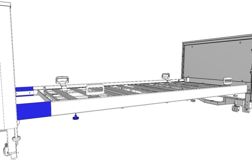
Instruction Manual for Lenus Care Bed

3 Assembly and putting into service

 This chapter is directed at professionals employed by the operator or medical
 supply retailer.

 3.1 TOOLS
 An assembly key is supplied.

 To ensure all bed components are securely fixed, all the screws of the bed
 must be tightened using the supplied assembly key. Tightening the screws by
 hand is not sufficient and can lead to bed components loosening during
 operation.
 • Tighten all the screws of the bed using the supplied assembly key.

 3.2 INCLUDED IN THE PACKAGE
 The bed is delivered unassembled, with the parts mounted on a storage aid. Assembly
 is carried out on site by the operator’s technical staff. The assembly work can be carried
 out by one or two persons.

 • Remove all packaging materials and cable ties before starting to assemble the bed.
 Observe the disposal instructions in chapter 10.

 Note: In order to prevent any damage to the bed chassis parts during transport and
 assembly, the head section chassis and the foot section chassis are each secured with
 a plastic screw (see 1).

 Attention! These screws must remain in place until the chassis have been mounted on
 the mattress base frame (see chapter 3.5). It is essential that these screws be removed
 before any electrical adjustments to the bed are made!

 1

 Page 17
Instruction Manual for Lenus Care Bed

3.3 LOCATION REQUIREMENTS
Note the following safety relevant aspects to take into account when selecting the site of use:
• There must be sufficient room available to accommodate the bed’s entire range of
 adjustments. There must be no furniture, windowsills, sloping roofs etc. in the
 adjustment path of the bed.
• The space underneath the bed must remain free.
• Before using the bed on parquet flooring, check whether the castors will leave stains
 on the parquet varnish. The bed can be used on tiles, carpet, linoleum or laminate
 flooring without causing any damage. BURMEIER is not liable for any floor damage
 that may be caused by day-to-day operation.
• A properly installed 230 volt mains socket must be available close to the bed (if
 possible) and available at any time.
• Position the bed so as to allow easy access to the power plug at all times so that the
 bed can be disconnected from the mains, if necessary.
• If any other additional equipment is attached to the bed, (e.g. compressors for
 positioning systems etc.), ensure that this is securely fastened and functions
 properly. Pay special attention here to the safe routing of all loose connector cables,
 tubing etc. If you have any queries or concerns, consult the manufacturer of the
 additional equipment or BURMEIER.

 Damage to flooring
 Damage to the flooring during assembly and dismantling of the bed may be
 caused by the sharp edges of the chassis or the mattress base.
 • Carefully assemble or dismantle the bed on protective covers to prevent
 damage to the flooring.

3.4 ASSEMBLING THE MATTRESS BASE FRAME
Proceed as follows to install the mattress base frame:
 Remove the safety side bars and the patient lifting pole from the storage aid and
 set them aside for the time being.
 Remove the two halves of the mattress base frame from the storage aid.
 Carefully place the head-end half and the foot-end half of the mattress base
 frame onto the floor. The four mattress retainer bars should face upwards, while
 the two drives face downwards.
 Then fit the two halves of the mattress base frame together.
 Set the long side of the mattress base frame on the floor and rest the frame
 against the wall.
 Remove the four long screws from the storage aid and use them to fix the two
 halves of the mattress base frame together (in the middle).
 Now carefully lay the assembled mattress base frame flat on the floor.

Page 18
Instruction Manual for Lenus Care Bed

3.5 ASSEMBLING THE CHASSIS

 Danger due to Trendelenburg position
 Failure to comply could result in serious injury to the person lying in bed.
 The two chassis [1] and [9] should not be confused! A mix-up will lead to an
 unwanted Trendelenburg position instead of a reverse-Trendelenburg
 position.
 • Take care not to confuse the two chassis when assembling the bed.
 • Observe the different labels for identification of the two chassis. These
 are located centrally on the cross tubes, near the holder for the drive
 motor and centrally on the cross tubes of the mattress base frame.

 Adhesive label on the head section chassis

 Adhesive label on the foot section chassis

Proceed as follows to attach the two chassis to the mattress base frame:
 Remove both chassis from the storage aid
 − To do so, pull the chassis out of the storage aid.
 Connect the head section chassis [9] to the mattress base frame [17]. Make sure
 that the adhesive labels match!
 − To do this, lift the mattress base frame at the head end and slide the two
 connection pieces of the head section chassis into the tubes of the mattress base
 frame as far as they will go.
 − Pull the head section chassis back out by approximately 10 mm until the holes
 are aligned one above the other.
 Fix the mattress base frame to the head section chassis with 2 long screws (M6x60,
 supplied with the bed).
 Repeat steps 2 and 3 with the foot section chassis [1].

 Check to ensure that the two chassis are securely fixed to the mattress base frame.
 Remove the plastic screws that secure the two chassis (see 1).
 − Use a 5 mm Allen key to remove them.
 − Save the plastic screws in case they are needed at a later date.
 Use the supplied plugs to seal the holes in the chassis (see 2).
 Note: The plugs can be found in the bag with the instruction manual.
 Page 19
Instruction Manual for Lenus Care Bed

 1

 2

Page 20
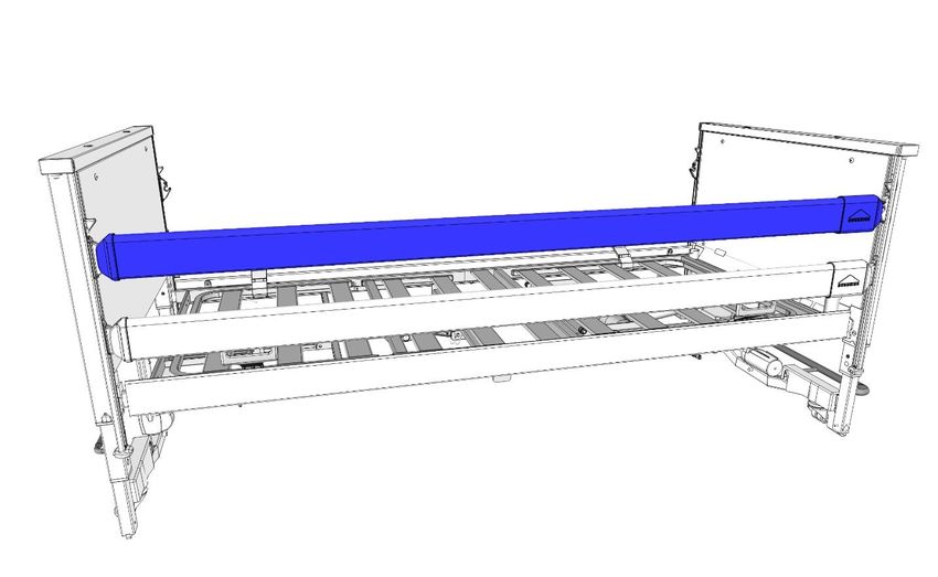
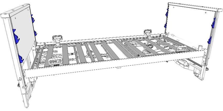
Instruction Manual for Lenus Care Bed

3.6 FITTING THE SIDE PANELS
The side panels are fixed to the longitudinal tube of the mattress base using screws.
Proceed as follows:
 Position the side panel, as shown, along the longitudinal tube of the mattress
 base 1 .
 Fasten the side panel to the inner side of the mattress base with the
 through-bolts and the washers (4x) 2 .
 Repeat steps 3 and 4 for the other side panel.

 Page 21
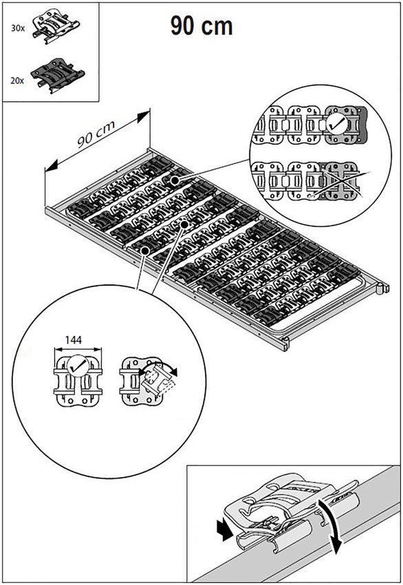
Instruction Manual for Lenus Care Bed

3.7 ATTACHING THE SAFETY SIDES
The bed is equipped with safety sides to protect the resident from accidentally falling out
of bed. The safety sides are made of bars with plastic end caps and are attached to the
bed with a simple click-on system. If necessary, they can be manually raised or lowered
by the carer.
On each chassis [3]+[9] there is one guide rail [11] on the left and one on the right. A
safety side guide runs in each of these guide rails. Each guide has two holding devices
for the bars. The safety side guides are pre-assembled at the factory. The safety side
bars can be quickly attached to the holding devices thanks to the simple click-on
system.

 Risk of injury and material damage
 Improperly installed safety side bars can fall and damage property or cause
 minor injuries.
 • Use only the safety sides described in this manual. Safety sides are either
 factory integrated into the bed or available as accessories.
 • After installing each safety side bar, check that it is correctly locked into the
 holding devices.
 • Operate the safety sides to check that they are correctly fitted and function
 properly (see chapter 4.6).

Proceed as follows:

 Move all the safety side
 guides to the top position a .
 a

 Start with the lower
 bar: Insert one end of the bar
 (plastic end cap) into the
 lower holding device at the
 head end of the bed.
 − Attention: The recess on the
 safety side bar must face
 inwards and the rounded side
 of the bar must face upwards.

Page 22
Instruction Manual for Lenus Care Bed

 Insert the other end of the bar into the lower
 holding device at the foot end of the bed. b
 − The bar must be securely held in place by the
 release button b .
 − Make sure that the bar is properly engaged by
 jiggling it up and down by hand.
 −

 Repeat steps 2 and 3 to attach the upper bar.

 Repeat steps 2 and 3 to attach the third and fourth
 bars, on the other side of the bed.

 Attention! After they have been installed, the bars can fall and cause injuries
 or damage to property if the release buttons [1] are jammed.
 − Push and pull the bars to check that they have been locked in
 place by the release buttons. It should not be possible to push
 the bars up or down.

 1

 Page 23
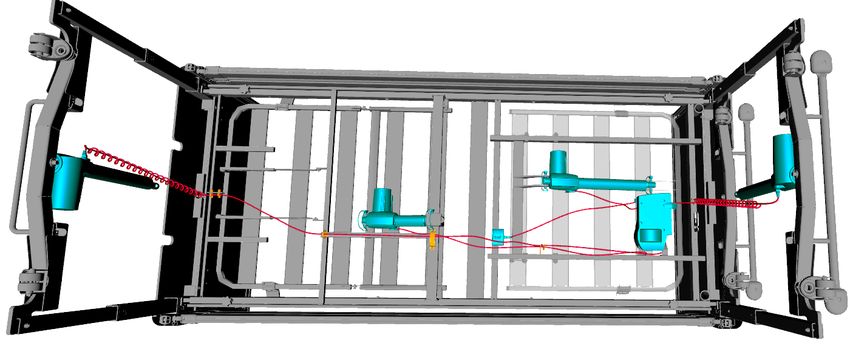
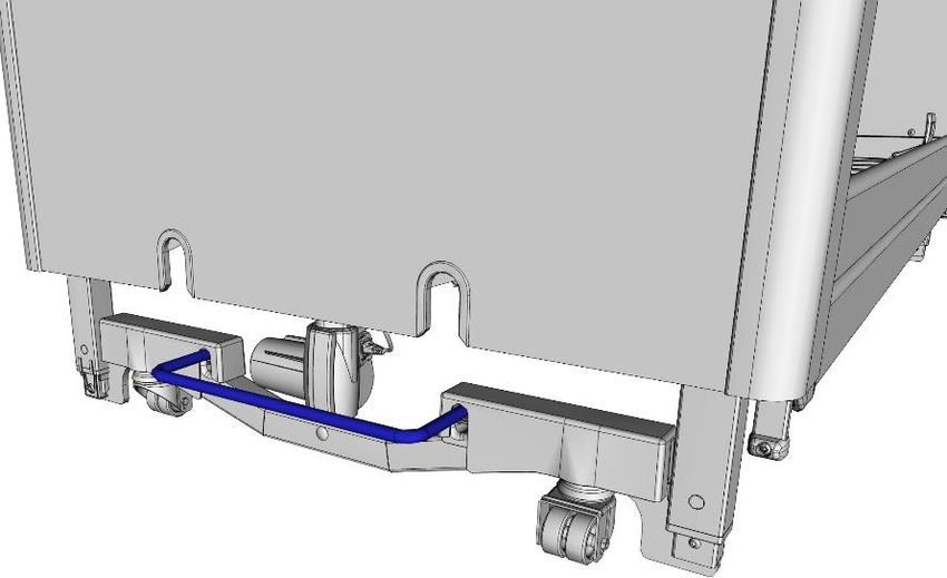
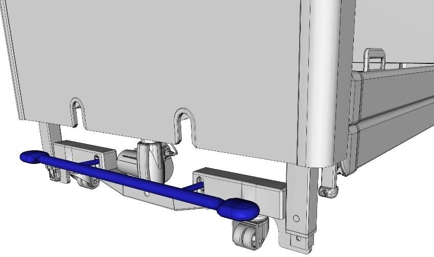
Instruction Manual for Lenus Care Bed

3.8 ELECTRICAL CONNECTION
Before you connect the cables, remove the packaging material from all the cables.
The 4 drive motors are supplied with electricity via the power adapter/power plug. All the
drive motor plugs are connected to the control unit during production and are secured
with a cover to prevent them from being unintentionally unplugged. The two plugs at the
ends of the spiral cable must be inserted into the correct lift motors on the head section
chassis and foot section chassis. The plug for the thigh rest motor must be plugged into
the thigh rest motor.

 When routing the connector cables, ensure that they cannot be damaged by any moving
 parts of the bed. To ensure that all the cables are laid safely and securely, the underside
 of the mattress base is equipped with cable holders (see arrows in picture).
 Use only these designated cable holders when routing and fixing the connector cables.

View of the bed from below.

Page 24
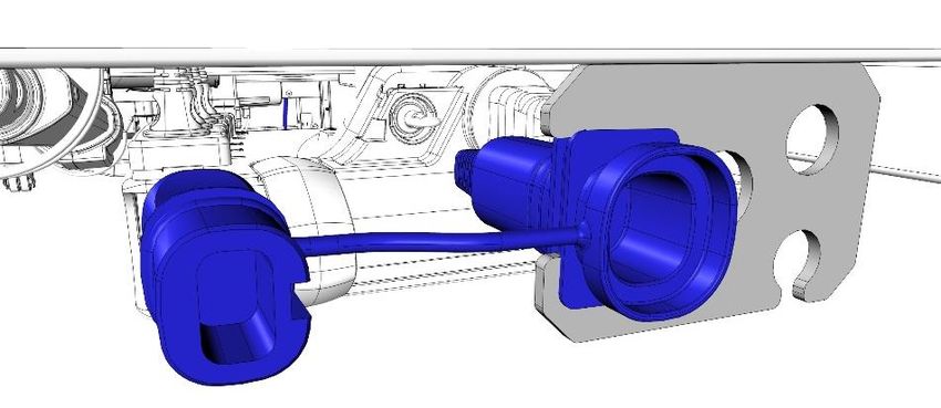
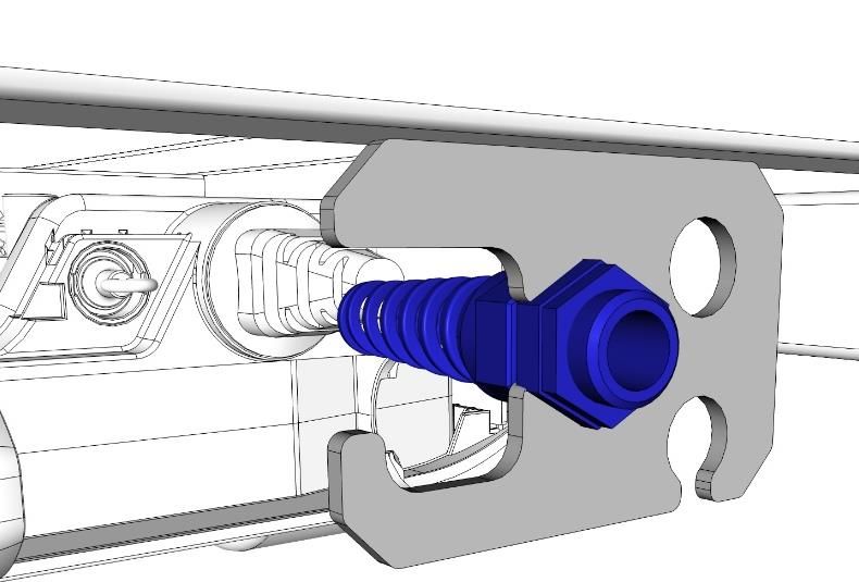
Instruction Manual for Lenus Care Bed

Proceed as follows:
 Insert the angled plug of the thigh rest motor
 into the connection socket on the thigh rest
 motor as far as it will go and secure the plug
 in place with the pull-out prevention device.
 Insert the plug of the head-end lift
 motor into the connection socket on the lift
 motor as far as it will go and secure the plug
 in place with the pull-out prevention
 device 1 .

 Insert the plug of the foot-end lift motor into
 the connection socket on the lift motor as far
 as it will go and secure the plug in place with
 the pull-out prevention device 1 .
 Only if necessary (usually the connection
 socket is pre-installed in the factory): attach
 the connection socket to the strain relief
 plate, which is located under the mattress
 base at the head end.
 The strain relief plate has two openings: a for
 beds powered via a power adapter and b for
 beds powered via a 230-volt supply cable.
 1
 If a power adapter is used:
 Insert the narrow end of the connection
 socket into the larger opening a of the strain relief plate.

 Page 25
Instruction Manual for Lenus Care Bed

 If a 230-V cable is used:
 Screw the 230-V cable into the smaller opening b of the strain relief plate, as
 shown. Attention: When laying the cable, follow the safety instructions in chapter
 3.9.

 a b

 a b

Page 26
Instruction Manual for Lenus Care Bed

3.9 CONNECTING THE POWER ADAPTER/POWER PLUG
Position the bed so as to allow easy access to the power plug at all times so that the
bed can be disconnected from the mains, if necessary.
3.9.1 Power adapter
Proceed as follows:
 Plug the power adapter into a mains socket.
 − The cable outlet must hang downwards
 (see picture).
 − Observe the following safety instructions!
 Insert the plug of the low-voltage
 cable into the connection socket.
3.9.2 Power plug
Plug the power plug into a mains socket.

 Damage to property due to routing cables incorrectly
 Cables that are incorrectly laid can cause damage to property when adjustments are
 made to the bed.
 • Lay all cables carefully.
 • Ensure that no cables are damaged, there are no loops and the cables are not
 squeezed by moving parts.
 • The electricity cable must not be run over by the castors when the bed is moved!
 • The cable from the power adapter/power plug must be laid to the connection
 socket at the head end in such a way that it lies between the cross tube and the
 headboard surround.
 Attention: If the cable is laid underneath the cross tube 1 and/or under the brake
 lever 2, the cable will be pulled/torn out of the connection socket when the bed is
 raised.

 Right Wrong

 2

 1

 Page 27
Instruction Manual for Lenus Care Bed

 Damage to the power adapter/power plug
 Failure to follow this information can result in irreparable defects in the power
 adapter/power plug and a short-circuit in the mains socket.
 Power adapter:
 • The mains socket you wish to use for the power adapter must NOT be
 under the bed. Otherwise, the moving mattress base frame may rip the
 power adapter out of the mains socket during horizontal adjustments.
 • Take care when adjusting the height: maintain a sufficient distance at the
 side between the bed and the power adapter to avoid damaging it.
 • The cable outlet must hang downwards (see
 picture on the next page).
 Power adapter/power plug:
 • Before moving the bed, always use the cable holder to hang the power
 adapter/power plug onto the bars of the safety sides. The cable holder is
 attached to the mains cable.
 • Before moving the bed, think about the length of the electrical cable;
 unplug the power adapter/power plug beforehand.

Page 28
Instruction Manual for Lenus Care Bed

3.10 PUTTING INTO SERVICE
It is only necessary to take an electrical measurement before putting the bed into
service for the first time if the bed has a 230-volt supply cable. In the case of beds with
a 24-volt power adapter, no electrical measurement is necessary, since these beds are
tested for electrical safety and functionality by the manufacturer before they leave
factory in perfect condition.
Before putting the bed into service for the first time:
• Remove all transport securing devices and packaging film.
• Clean and disinfect the bed.
• Allow the bed to acclimatise to room temperature for about 20 minutes if it was stored
 beforehand at the lowest or highest permissible temperature (see chapter 9.4on
 storage temperature).
• Perform an initialisation of the control unit (see chapter 6.5.4).
• After the bed has been assembled, carry out a check in accordance with the
 checklist in chapter 3.10.1.
Before putting the bed into service each time:
Check that:
- The bed has been cleaned and disinfected.
- The castors are braked.
- The power supply is compatible with the technical data of the bed (230 volt AC, 50/60
 Hz).
- Easy access to the mains plug is ensured at all times so that the bed can be
 disconnected from the mains, if necessary.
- The power adapter/power plug is plugged in and the cable is routed in such a way
 that it cannot be damaged during bed adjustments or by being driven over.
- The power adapter/power plug, drive cables and handset cable cannot be damaged
 by moving parts of the bed.
- No obstacles such as bedside cabinets, supply rails or chairs will inhibit adjustments.
- All adjustment functions are in proper working order and have been checked (see
 chapter 3.10.1).

The care bed may be put into operation only after all these checks have been
carried out!

 Page 29
Instruction Manual for Lenus Care Bed

3.10.1 Checklist: Inspection by the user

 Check O Not Description
 WHAT ? HOW ? K OK of defect
 Visual inspection of the electrical components
 Handset Damage?
 Handset cable Damage, cables routed
 Power adapter away from moving parts?
 Visual inspection of the mechanical components
 Patient lifting pole, lifting Damage, cracks
 pole sleeves, grab handle
 with strap (optional features)
 Chassis Damage, deformations?
 Mattress base Damage?
 Wooden surround Damage, splinters?

 Safety sides Damage, deformation,
 splinters?
 Functional check of the electrical components
 Handset, locking functions Functional test

 Rests Functional test
 Height adjustment Functional test
 Reverse-Trendelenburg Functional test
 position
 Special function, adjustment Functional test: Warning
 to an even lower position tone and half-speed lowering

 Functional check of the mechanical components
 Castors Braking, moving
 CPR release of backrest Test according to instruction
 manual
 Safety sides Locked in place, unlocked?
 Accessories (e.g. patient Suitability, secure fastening,
 lifting pole, grab handle) damage?

 Inspector’s signature: Inspection result: Date:

 If damage or a malfunction is suspected, the care bed must be withdrawn
 from service immediately and disconnected from the mains supply until the
 defective parts have been repaired or replaced!
 Report this immediately to the operator!

Page 30
Instruction Manual for Lenus Care Bed

4 Operation

 4.1 TIPS ON USING THE BED SAFELY IN A DOMESTIC SETTING
 Please use the following table to help identify and avoid any unfavourable conditions of
 use.
 Unfavourable conditions of use Avoid by

 Electrical equipment:
 Damage to handsets/connecting Hang the handset on the hook
 cables Do not pull the cables right across the bed/do
 not run over them with the castors
 Electrical adjustment functions are Block the functions on the handset if they
 not blocked; body parts could be could otherwise place the occupant or
 trapped as a result of unintentional children in danger; do not leave children
 activation unsupervised in the room with the bed
 Possibility of overheating due to fluff If necessary, use a dry cloth to remove dust
 and dust on electrical drive from the drive components under the
 components mattress base
 Pets can eat through electrical Do not allow rodents to run around freely in
 cables: this could cause malfunctions the same room as the bed
 and electric shocks

 Safety sides:
 Possibility of trapping/strangulation When the occupant is particularly small,
 when using safety sides emaciated or confused: use the safety sides
 only with additional protection measures or
 not at all
 Interfering devices/objects close to the bed
 Fire hazard due to heat generated by Use only LED reading lamps that do not heat
 a reading lamp, heater etc. up
 Use devices only if they are in good working
 order and are used in accordance with their
 operating instructions; keep them at a safe
 distance from the bed
 Collision hazard/damage to property Ensure a safe distance from other
 resulting from bed adjustments objects/sloping ceilings/windowsills

 Crushed connecting cables or hoses Route and fix cables and hoses in such a
 from compressed air positioning way that they cannot be trapped during bed
 systems; inhalers etc. adjustments

 Page 31
Instruction Manual for Lenus Care Bed

4.2 MOVING AND BRAKING THE BED
The bed is equipped with four lockable castors, which can be braked in pairs (at the
head end and foot end of the bed) (10). The bed can be moved within the room even
when the bed is occupied.

 • A bed that is occupied by someone should be moved around only inside
 the room. Always avoid moving the bed over long distances along
 corridors and across thresholds.
 • Each time before moving the bed, ensure that:
 o The mains cable cannot be stretched, driven over or damaged in any
 other way.
 o The power adapter is always hooked onto the safety side bars using
 the mains cable holder and the cable does not trail on the floor.
 o All cables, tubes or leads belonging to any accessory devices that are
 attached to the bed are safely secured and cannot be damaged.
 Otherwise the mains cable could sustain damage as a result of being
 torn off, crushed or driven over. Such damage could lead to electrical
 hazards and malfunctions.
 • Braking: In order to brake the bed, always brake all four castors. This is
 particularly important if the bed and resident are left unsupervised or the
 bed is on a sloping floor (e.g. on a ramp). A safe and secure bed position
 must always be ensured!
 - Exception: When the bed is to be adjusted to the Trendelenburg or
 reverse Trendelenburg position
 , either the head-end or foot-end castors must be unbraked. This
 allows the bed to compensate for the movement of the two lift
 motors without the castors causing damage to the floor (castor
 tracks).

Page 32
Instruction Manual for Lenus Care Bed

4.2.1 Individual axle braking

Brake bar - operated from the foot end
This operates the foot-end castors.

To move the bed:
Lift the brake bar with your foot.

To brake the bed:
Press the brake bar down with your
foot.

Brake lever - operated from the head end
This operates the head-end castors.

To move the bed:
Raise the brake lever with the your
foot.

To brake the bed:
Press the brake lever down with
your foot.

 Page 33
Instruction Manual for Lenus Care Bed

4.3 MECHANICAL ADJUSTMENT OPTIONS
4.3.1 Lower leg rest (LR)
The lower leg rest 1 can be raised and lowered manually when the thigh rest is raised
2.
It is possible to adjust the bed to an orthopaedic (stepped bed) position or so that the
lower leg rest is sloping downwards.

 3
 Similar to illustration!

 2 1
 3

Manually adjusting the lower leg rest (LR)
Raise the thigh rest using the handset.
Taking hold below the frame 3 , lift the lower leg rest to the desired position and then
release it slowly.
 • The lower leg rest engages automatically.
If necessary, correct the bed position using the handset (thigh rest button).

Manually lowering the lower leg rest

 Pay attention to the order of the operating instructions!
 • Raise the lower leg rest until it reaches the upper limit stop on the frame.
 • Then lower the lower leg rest slowly.
 • Risk of crushing! Hold the lower leg rest only at the place indicated 3 .
 There is a risk of injury occurring if the lower leg rest falls unchecked.

Page 34
Instruction Manual for Lenus Care Bed

Lowering the lower leg rest using the handset
If the thigh rest is lowered using the handset, the lower leg rest is automatically lowered
as well.
Raising the lower leg rest using the handset
If the thigh rest is raised using the handset, the lower leg rest is automatically moved as
well and locks into place in several intermediate positions. When the thigh rest is raised,
the lower leg rest remains in position.

4.3.2 Manual CPR release of the backrest
In the event of power supply outages or electrical drive system failures, a raised
backrest 1 can be lowered by hand.

 Please note: manual emergency release of the backrest must be carried out by
 two people!

 Disregard for this safety information and instructions for use may cause
 the backrest to fall uncontrollably, which could lead to serious injuries
 for both the user and the resident!
 • The CPR release may only be carried out in the case of extreme
 emergencies and by users who have a complete command of the
 procedure described below.
 • We strongly advise you to practise CPR release of the backrest several
 times under normal conditions. In the event of an emergency you will then
 be able to react quickly and correctly.

 Similar to illustration!

Before you lower the backrest,
1 any load exerted on the 4 1
backrest must be removed. 2
• To do this, the first person
 takes hold of the backrest
 frame 2 and raises the
 backrest slightly, keeping it
 held firmly in this position.
 3
• The second person now
 removes the bolt 4 . To do
 this, fold back the curved clip
 .3. and pull the bolt and clip
 out of the lifting bar of the backrest motor.

 Page 35
Instruction Manual for Lenus Care Bed

• The motor is now disconnected
 from the backrest. 4
• Put the motor down on the bed
 frame.
• After the second person has left
 the danger zone, the first person
 (with the help of the second
 3
 person) lowers the backrest
 carefully.

 Hold the backrest firmly when lowering it, as it could otherwise fall
 unchecked!

• Now the motor on the lifting bar is no longer connected to the motor connector
 mount.
• The lifting bar remains in the CPR release position.

Restoring the bed to its original state following CPR release of the backrest
• Raise the backrest by hand.
• Swing the lifting bar up again, use the bolt to secure it in place in the motor connector
 mount and fold the curved clip back over.

Page 36
You can also read