WASP USER MANUAL Wireless Acceleration Sensor Puck - Wireless Sensors
←
→
Page content transcription
If your browser does not render page correctly, please read the page content below

WASP™
Wireless Acceleration
    Sensor Puck

  USER MANUAL

     VERSION 3.20
      15/07/2016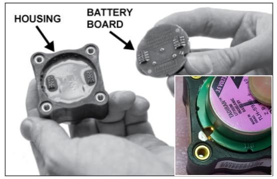
WASP™ is a registered trademark owned by
                BossPac Engineering & Technology

      WASP™ is a PATENT PENDING technology owned by
                BossPac Engineering & Technology

                BossPac Engineering & Technology
    1450 – 28 Street NE Bay 8, Calgary, Alberta, Canada T2A 7W6
Phone: (403) 216-1226 Fax: (403) 216-5557 E-Mail: info@bosspac.com
      Visit our website for more information www.bosspac.com
WASPTM Wireless Acceleration Sensor Puck Operations Manual

                     WARNING
 READ THIS MANUAL BEFORE OPERATING THIS DEVICE.

               MISE EN GARDE
         LISEZ LE MANUEL AVANT UTILISATER

                     WARNING
  TO PREVENT EQUIPMENT FAILURE, AND/OR DAMAGE,
  AND/OR PERSONAL INJURY, REGULAR CALIBRATION
    AND INSPECTION OF THIS DEVICE IS REQUIRED.

               MISE EN GARDE
POUR PRЀVENIR LE DOMMAGE À L’EQUIPMENT, ET/AU AUX
PERSON, LA CÀLIBRATION ET L’INSPECTION REGULIER EST
                     ŔEQUIS.

                           -1-
WASPTM Wireless Acceleration Sensor Puck Operations Manual
WARNING - EXPLOSION HAZARD
SUBSTITUTION OF COMPONENTS MAY IMPAIR
SUITABILITY FOR CLASS 1, DIVISION 2
AVERTISSEMENT – RISQUE D’EXPLOSION
LA SUBSTITUTION DECOMPOSANTS RENDRE CE MATÉRIEL
INACCEPTABLE POUR LES EMPLACEMENTS DE CLASSE 1,
DIVISION 2
WARNING - EXPLOSION HAZARD
DO NOT REMOVE BATTERIES UNLESS
AREA IS KNOWN TO BE NON-HAZARDOUS.
AVERTISSEMENT - RISQUE D’EXPLOSION
AFIN D’ÉVITER TOUT RISQUE D’EXPLOSION, S’ASSURER QUE
L’EMPLACEMENT EST DÉSIGNÉ NON DANGEREUX AVANT
CHANGER LA BATTERIE.
-2-WASPTM Wireless Acceleration Sensor Puck Operations Manual
Table of Contents
1. Introduction ......................................................................................................................... 4
2. Installation........................................................................................................................... 4
2.1. Assembling Of Wireless Sensor Pucks ........................................................................ 4
2.1.1 Battery Installation ..................................................................................................... 4
2.1.2 Sensor Activation ........................................................................................................ 4
2.1.3 Cap and Gasket Installation.......................................................................................... 5
2.1.4 WASP™ LED Error Indicator ........................................................................................ 5
2.2. Placement Of The WASP™ Pucks .............................................................................. 6
2.2.1 WASP™ Mounting........................................................................................................ 6
2.3. Optional Thermal Calibration Of WASP™s .................................................................. 6
3. Troubleshooting WASP LED Flash Codes .......................................................................... 7
3.1. LED Flash Codes ......................................................................................................... 7
3.2. What To Do When An Error Is Reported? .................................................................... 8
3.3. Contact Info ................................................................................................................. 8
-3-WASPTM Wireless Acceleration Sensor Puck Operations Manual
1. Introduction
This Operations Manual provides basic information on how to operate the
WASP™Wireless Acceleration Sensor Puck
This manual covers the following topics:
Installation of WASP™
Assembling of WASP™
Placement of WASP™
Optional Thermal Calibration of WASP™
Troubleshooting
2. Installation
2.1. Assembling Of Wireless Sensor Pucks
2.1.1 Battery Installation
Each sensor puck is shipped with a separate Battery Circuit Board Assembly. The
battery circuit board contains a non-removable long lasting lithium battery, (permanently
secured to pcb).
WARNING – USE ONLY WITH REPLACEABLE BATTERY BOSSPAC EA000166
WARNING – EXPLOSION HAZARD. DO NOT REMOVE BATTERIES UNLESS AREA IS
KNOWN TO BE NON-HAZARDOUS.
AVERTISSEMENT – RISQUE D’EXPLOSION. AFIN D’ÉVITER TOUT RISQUÉ D’EXPLOSION,
S’ASSURER QUE L’EMPLACEMENT EST DÉSIGNÉ NON DANGEREUX AVANT CHANGER LA
BATTERIE.
2.1.2 Sensor Activation
To turn on and activate each sensor puck you must carefully attach the battery board to
the sensor unit. Plug the pins on the battery board into the corresponding sockets on the
sensor puck housing. See Figure 1:
It is important that the Battery PCB Assembly and the WASP™ Sensor are oriented
correctly. Failure to orient the battery with the WASP™ can cause damage to the battery
pins and will damage the Sensor. This is done by lining up the white or silver mark on
the WASP™ main housing with the largest cutout on the battery board as show in figure
below. Newer sensor housing also have a small notch at the location of the white
marking.
Once the pins make contact a LED on the battery module board will turn on to indicate
power on. During this time, the WASP™ device performs a power-on self test (POST).
The LED will flash quickly for a couple of seconds and then turn off to indicate this cycle.
-4-WASPTM Wireless Acceleration Sensor Puck Operations Manual
Figure 1: Install WASPTM Battery Board
2.1.3 Cap and Gasket Installation
Each sensor includes a Gylon 3545 gasket to be placed between housing and top cap.
This gasket is required for the sensor to maintain an IP54 rating. There is no specific
orientation required for the top cap; and it is retained by four 8-32 stainless steel screws.
WARNING – DO NOT REMOVE FOUR SCREWS ON THE BOTTOM OF THE DEVICE
2.1.4 WASP™ LED Error Indicator
Should the POST (Power On Self Test) fail, the device locks up and flashes the LED in
a discernible pattern to help diagnose the source of the problem. See the section at the
end of this manual on troubleshooting for details on the LED flash codes.
-5-WASPTM Wireless Acceleration Sensor Puck Operations Manual
2.2. Placement Of The WASP™ Pucks
2.2.1 WASP™ Mounting
The sensor pucks can be attached to the desired equipment by the supplied magnet
base. Optional methods of epoxy or stud mounted can be used. The supplied magnets
have an effective operating range of -40°C to 185°C (-40°F to 365°F)
WARNING – THE RARE EARTH MAGNET BASE PLATE HAS IN EXCESS OF 50
LBS OF FORCE AND CAN CAUSE HARM IF CARE IS NOT TAKEN
To ensure effective wireless transmission between the sensor pucks and the receiver
it is recommended that there is a direct line of sight between the units.
▪ It is recommended that the surface is prepared for the installation of the WASP™
sensors.
▪ Ensure the surface is clear of debris and excess paint.
▪ Ensure the magnetic base is screwed securely to the stud on the bottom of the WASP™.
▪ Ensure the top screws are tightened to a maximum of 15 ft. lb or 1.7 N m
▪ It is recommended to fill the center section of the magnetic base plate with a small
amount of SILICON HEAT TRANSFER COMPOUND to facilitate the most efficient heat
transfer from the mounting surface into the sensor.
▪ Carefully set the sensor into place. Avoid snapping with the magnet base as it can
damage the magnet.
2.3. Optional Thermal Calibration Of WASP™s
To ensure the greatest accuracy of the monitored variables it is optional to do thermal
calibration of each WASP™ unit. The process of thermal calibration is as follows:
▪ Ensure the machinery for which the WASP™ is to be attached is at operating
temperature.
▪ Place the WASP™ (s) units at their desired mounting points using thermal paste. Allow
15 minutes for the temperature to stabilize.
▪ Using a thermometer gun, record the temperature value at the valve cap at the mounting
point of the WASP™ unit.
▪ At the receiver, adjust the display temperature to match the value of the thermometer
gun using the temperature offset function. (See the section on temperature calibration in
the “Setting Temperature Warning and Critical Alarm Thresholds” section of this
manual).
-6-WASPTM Wireless Acceleration Sensor Puck Operations Manual
3. Troubleshooting WASP LED Flash Codes
3 . 1 . L E D F l a s h Co d e s
The following table contains a brief description of all flash codes reported by the device:
-7-WASPTM Wireless Acceleration Sensor Puck Operations Manual
3.2. What To Do When An Error Is Reported?
Accelerator Failure (1-Flash)
This is indicative of an electrical failure: either the accelerometer isn’t receiving power or the
device has lost electrical connectivity between the MCU and the accelerometer. In either
event, the device is inoperative. Recommend replacing the WASP unit.
Battery Failure (2-Flash)
Recommend removing and reconnecting the battery as sometimes the power connectors do
not mate evenly. If the problem still persists, replace the battery board.
Temperature Sensor Failure (3-Flash)
Assuming that the device isn’t powering up in extreme temperatures, this is indicative of an
electrical fault with the RTD. Recommend replacing the WASP unit.
Radio Failure (4-Flash)
Much like an accelerometer failure, this is indicative of an electrical failure. The problem is
much more severe in this instance as device cannot communicate. Recommend replacing
the WASP unit.
Regulator Failure (5-Flash)
This is indicative of an electrical failure. Replace the WASP unit.
3 . 3 . Co n t a c t I n f o
BossPac engineers can be reached at:
Email: support@bosspac.com
Ph: +1 403-216-1226 Toll Free: 866 616-1226
BossPac Engineering & Technology
1450 28th Street NE, Bay 8, Calgary, Alberta, CANADA T2A 7W6
www.bosspac.com
-8-WASPTM Wireless Acceleration Sensor Puck Operations Manual
FCC & IC Statements
FCC Class B Part 15
This device complies with part 15 of the FCC Rules. Operation is subject to the following two
conditions: (1) This device may not cause harmful interference, and (2) This device must accept
any interference received, including interference that may cause undesired operation.
Changes or modifications not expressly approved by BossPac Engineering Technology Inc.
may void the user’s authority to operate the equipment.
IC RSS 210
This device complies with Industry Canada licence-exempt RSS standard(s). Operation is
subject to the following two conditions: (1) this device may not cause interference, and (2) this
device must accept any interference, including interference that may cause undesired operation
of the device.
Le présent appareil est conforme aux CNR d'Industrie Canada applicables aux appareils radio
exempts de licence. L'exploitation est autorisée aux deux conditions suivantes : (1) l'appareil ne
doit pas produire de brouillage, et (2) l'utilisateur de l'appareil doit accepter tout brouillage
radioélectrique subi, même si le brouillage est susceptible d'en compromettre le
fonctionnement.
FCC/IC RF Exposure Statement
This equipment complies with FCC radiation exposure limits set forth for an uncontrolled
environment. The antenna(s) used for this equipment must be installed to provide a separation
distance of at least 8 inches (20cm) from all persons.
Cet équipement est conforme à l'exposition aux radiations de FCC et d'Industrie Canada
établies pour un environnement non contrôlé. L'antenne (s) utilisé pour cet équipement doit être
installé pour fournir une distance d'au moins 20cm à partir de toutes les personnes.
-9-You can also read