WATER & SEWER PIPE STANDARDS - OF BURTON UTILITIES - Village of Burton
←
→
Page content transcription
If your browser does not render page correctly, please read the page content below
WATER & SEWER PIPE STANDARDS
       OF BURTON UTILITIES
TABLE OF CONTENTS

WATER - GENERAL PIPE REGULATIONS                                                                                                                                                    1
 SECTION I – Potable Water Service Pipe                                                                                                                                             3
   A.   TYPE “K” SOFT COPPER TUBE (ASTM B88) ............................................................................................................... 3
   K.   TRACER WIRE – 12 AWG SOC 10 PE (COLOR-BLUE) or LARGER. .............................................................................. 4
 SECTION II – Potable Water Main Pipe                                                                                                                                               4
   A.   CLASS 52 CEMENT LINE DUCTILE CAST IRON PIPE WITH PUSH ON JOINT – (ANSI A21.51, AWWA C151)............... 4
 SECTION III – Water Line Components                                                                                                                                                4
   A.   DUCTILE IRON PIPE ................................................................................................................................................... 4
   B.   JOINTS ...................................................................................................................................................................... 4
   C.   DUCTILE IRON FITTINGS ........................................................................................................................................... 4
   D.   NUTS AND BOLTS ..................................................................................................................................................... 4
   E.   TAPPING VALVE ........................................................................................................................................................ 4
   F.   TAPPING SLEEVE ....................................................................................................................................................... 5
   G.   CORPORATION STOPS AND VALVES (3/4 “, 1”) ........................................................................................................ 5
   H.   CURB STOPS AND VALVES ........................................................................................................................................ 5
   I.   CURB VALVE BOX WITH ROD ................................................................................................................................... 5
   J.   ROADWAY VALVE BOX ............................................................................................................................................. 5
   K.   GATE VALVE.............................................................................................................................................................. 5
   L.   FIRE HYDRANTS ........................................................................................................................................................ 5
        1. Inlet Connection .................................................................................................................................................. 5
        2. Hoses and Nozzles ............................................................................................................................................... 6
        3. Mueller No. A-423 Centurion Fire Hydrant Main Valve and Seat Ring ................................................................ 6
           3a. Hydrant Barrel ............................................................................................................................................. 6
           3b. Valve and Drain Stem .................................................................................................................................. 6
        4. Detailed Specifications......................................................................................................................................... 7
   M.   APPROVAL ................................................................................................................................................................ 7
 SECTION IV – Remote Water Meter Installation                                                                                                                                     22
   A.   GENERAL SPECIFICATIONS ..................................................................................................................................... 22
   B.   WATER METER INSTALLATION IN OUTSIDE PIT...................................................................................................... 22
 SECTION V – Hydrostatic Water Line Testing                                                                                                                                       26
   A.   PRESSURE TEST....................................................................................................................................................... 26
        1. Test Pressure ..................................................................................................................................................... 26
        2. Restrictions ........................................................................................................................................................ 26
        3. Pressurization .................................................................................................................................................... 26
        4. Air Removal ........................................................................................................................................................ 26
   B.   LEAKAGE TEST ........................................................................................................................................................ 27
        3. Allowable Leakage at Various Pressures ............................................................................................................ 27
   C.   DISINFECTION .................................................................................................................................................... 27-28

SEWER - GENERAL PIPE REGULATIONS                                                                                                                                            30-31
 SECTION VI – Sanitary Sewer Pipe                                                                                                                                                 34
   A.   GENERAL SPECIFICATIONS ..................................................................................................................................... 35
   B.   SUPPLIERS OF MANHOLE FRAMES AND LIDS ......................................................................................................... 36
   C.   MANHOLE RISERS ................................................................................................................................................... 36
 SECTION VIII – Specification for Sanitary Sewer Drop Manholes                                                                                                                    36

                                                                                      ii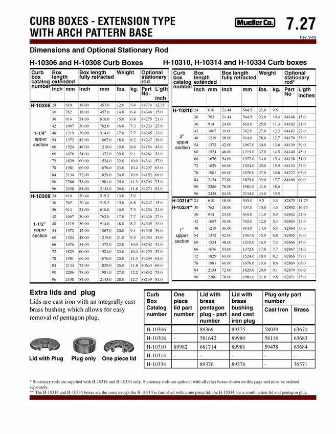
TABLE OF CONTENTS
SECTION IX – Service Connections                                                                                                                                                38
  A.   PLANNED SERVICE CONNECTIONS ......................................................................................................................... 38
  B.   UNPLANNED SERVICE CONNECTIONS .................................................................................................................... 38
  C.   CONNECTIONS ........................................................................................................................................................ 38
  D.   INSERTA-TEE INSTALLATION PROCEDURE .............................................................................................................. 38
SECTION X –Specification for Polyvinyl Chloride (PVC) Sewer Pipe and Fittings for Sanitary Sewer
Installations                                                                                                                                                                   40
  A.   POLYVINYL CHLORIDE (PVC) PIPE ........................................................................................................................... 40
       1. Home Mark ........................................................................................................................................................ 40
       2. Fittings ............................................................................................................................................................... 40
       3. Lubricant ............................................................................................................................................................ 40
       4. Certificate .......................................................................................................................................................... 40
       5. Manufacturer’s Installation Instructions ........................................................................................................... 40
       6. Straightness ....................................................................................................................................................... 40
       7. Prior Inspection .................................................................................................................................................. 40
       8. Exposure to Sunlight .......................................................................................................................................... 40
  B.   PIPE JOINTS ............................................................................................................................................................ 41
       1. Joint Testing ....................................................................................................................................................... 41
       2. Test Specimens .................................................................................................................................................. 41
SECTION XI – Isolation of Sanitary Sewer Extensions                                                                                                                             41
SECTION XII – Sanitary Sewer Pipe Installation                                                                                                                                  43
  A.   SAFETY .................................................................................................................................................................... 43
  B.   HANDLING .............................................................................................................................................................. 43
  C.   PROTECTION OF TREES .......................................................................................................................................... 43
  D.   DE-WATERING ........................................................................................................................................................ 43
  E.   CONSTRUCTION EQUIPMENT................................................................................................................................. 43
  F.   EXCAVATION AND CONSTRUCTION MATERIALS .................................................................................................... 43
  G.   TRENCH SUPPORTS ................................................................................................................................................ 43
  H.   NOISE DUST AND ODOR CONTROL ....................................................................................................................... 44
  I.   ALIGNMENT AND GRADE ....................................................................................................................................... 44
       1. Batter Boards ..................................................................................................................................................... 44
       2. Laser Beam......................................................................................................................................................... 44
  J.   PIPE JOINT INSTALLATION ...................................................................................................................................... 44
  K.   FIELD CUTTING ....................................................................................................................................................... 45
  L.   TRENCH EXCAVATION AND BOTTOM PREPARATION ............................................................................................. 45
       1. Trench Bottom ................................................................................................................................................... 45
       2. Trench Width ..................................................................................................................................................... 45
          2a. Earth excavation ....................................................................................................................................... 45
          2b. Rock excavation ........................................................................................................................................ 46
       3. Foundation ......................................................................................................................................................... 46
  M.   PIPE BEDDING AND INSTALLATION ........................................................................................................................ 46
       1. Pipe Bedding ...................................................................................................................................................... 46
       2. Haunching .......................................................................................................................................................... 46
       3. Pipe Laying ......................................................................................................................................................... 46
  N.   TRENCH BACKFILL ................................................................................................................................................... 46
       1. Initial Backfill ...................................................................................................................................................... 46
       2. Initial Backfill Material ....................................................................................................................................... 47
       3. Final Backfill ....................................................................................................................................................... 47
       4. Backfilling Under pavements Driveways, etc ..................................................................................................... 47
       5. Casings ............................................................................................................................................................... 47
       6. Bulkheads........................................................................................................................................................... 49

                                                                                    iii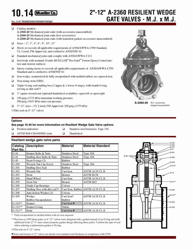
TABLE OF CONTENTS
        7. Surface Conditions ............................................................................................................................................. 49
   O.   CONSTRUCTION AREA ............................................................................................................................................ 49
 SECTION XIII – Inspection and Testing                                                                                                                                          49
   A.   CLEANING ............................................................................................................................................................... 49
   B.   LEAKAGE TEST PROCEDURE ................................................................................................................................... 50
        1. Infiltration Test .................................................................................................................................................. 50
        2. Exfiltration Test .................................................................................................................................................. 50
        3. Sanitary Force Mains ......................................................................................................................................... 50
        4. Water ................................................................................................................................................................. 50
   C.   LEAKAGE ALLOWANCE ........................................................................................................................................... 51
        1. Gravity Sewers ................................................................................................................................................... 51
        2. Force Mains ....................................................................................................................................................... 51
   D.   DEFLECTION TEST ................................................................................................................................................... 51

DIRECTORY of BURTON UTILITIES CONTACTS                                                                                                                                          52

                                                                                    iv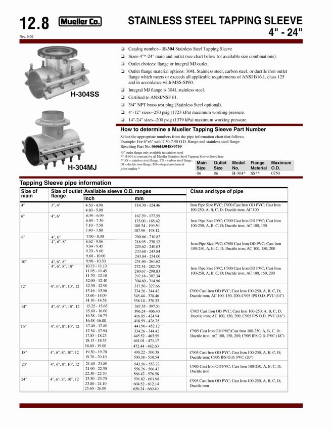
WATER - GENERAL PIPE REGULATIONS

1.    All Iron and steel products use for the construction alteration maintenance for repair of water systems
      or treatment works are to be AIS compliant and products that are produced in the United States. The
      American Iron and Steel (AIS) provision of the 2014 Consolidated Appropriations Act requires Clean
      Water State Revolving Fund (CWSRF) and Drinking Water State Revolving Fund (DWSRF) assistance
      recipients to use iron and steel products that are produced in the United States. This requirement applies
      to projects for the construction, alteration, maintenance, or repair of a public water system or public
      treatment works, unless a waiver is granted or 1 of 3 of the following exceptions applies (non-availability,
      unreasonable cost or inconsistent with the public interest).”

2.    All water lines shall be installed with a minimum of four (4) feet of cover.

3.    Sizing of water mains to accommodate future growth shall be determined by Burton Utilities.

4.    All costs for water improvements, including necessary over-sizing, shall be borne by the developer.

5.    All water mains shall be extended to the farthest property line of the developer to accommodate future
      growth. Water mains shall be looped/connected with other existing mains when possible to maintain
      water quality. All water mains that are not looped/connected with other existing mains shall end with
      an “in line valve”, a fire hydrant and watch valve, and have at least two (2) full lengths of pipe of proper
      diameter beyond the valve. The end of the line shall be plugged and blocked and marked. Said main
      extensions shall be at the expense of the developer.

6.    All water installations shall be bedded in, and backfilled to 12 inches above the pipe with #57 bank run
      wash gravel. All trenches under paved areas shall be backfilled and properly compacted to finished
      grade with #411/304 limestone.

7.    All water pipes, fittings, hydrants, manholes, manhole castings and lids, meter pits and other
      appurtenances and incidentals shall conform to specifications and standards as specified in the
      “WATER & SEWER PIPE STANDARDS” for the Burton Utilities.

8.    All water service taps shall be a minimum of one (3/4) inch diameter.

9.    Flared or compression fittings are required on all copper service connections to be maintained by the
      Village.

10.   All water service lines from the main to the curb valve shall be Type “K” soft copper tube or Class 52
      cement lined ductile iron pipe as specified herein.

11.   All water service lines from the curb valve to the building may be Type K soft copper tube, Class 52
      cement lined ductile iron pipe or approved plastic pipe as specified in Table 2. All water mains to be
      maintained by the Village shall be Class 52 cement lined ductile iron pipe and fittings shall be a
      minimum of eight (8) inches in diameter.

12.   All CTS water pipes and fittings must be accompanied by a manufacturer certificate that the pipe and
      fittings were manufactured and tested in accordance with the appropriate ASTM or AWWA
      specification. Said certificate shall be submitted to the Burton Utilities prior to the installation of the
      pipe.
                                                        1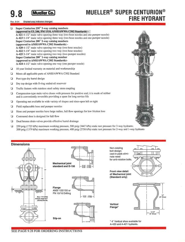
13.   All fire hydrants to be maintained by the Village shall be approved by Burton Village and meet the
      specifications contained herein. Hydrants shall be installed at a maximum spacing of 300 feet in all
      areas, except that a hydrant shall be installed at the end of all lines. All hydrants shall be equipped with
      a watch valve.

                                                       2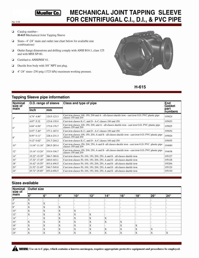
SECTION I – Potable Water Service Pipe

A.       TYPE “K” SOFT COPPER TUBE (ASTM B88)
        Nominal Size                   Minimum Wall                     Safe Working                        O.D.
          (inches)                       Thickness                        Pressure
              ¾”                             .065                            680                            .875
              1”                             .065                            680                           1.125
             1 ¼”                            .065                            550                           1.375
             1 ½”                            .072                            520                           1.625
              2“                             .083                            450                           2.125
             2 ½”                            .095                            420                           2.625
              3“                             .109                            410                           3.125
             3 ½”                            .120                            380                           3.625
              4”                             .134                            370                           4.125
              5”                             .160                            360                           5.125
                                                   Table 1 – Type “K” Soft Copper Tube Specs

C.       PE 3408 CTS WATER SERVICE TUBING – BLACK WITH BLUE STRIPES (ASTM D 2737, NFS #14)
         SDR 9, 200 PSI
                                                                           Minimum             Weight
                                            Size            O.D.
                                                                             Wall              Per 100’
                                             ¾”             .875            .0097                10.3
                                             1”             1.125            .125                16.8
                            200 PSI
                                            1 ¼”            1.375            .153                24.9
                             DR-9
                                            1 ½”            1.625            .181                34.9
                                             2”             2.125            .236                59.7
                                         Table 2a – CTS Water Service Tubing – Black w/blue stripes

PRESSURE RATINGS: All pressure ratings are a maximum PSI @ 73.4°F. If temperatures exceed 80°F, contact Charter Plastics for a
working pressure derating.
INSTALLATION: All Charter PE 3408 CTS Tubing can be direct buried, plowed or pulled. This pipe is not designed for in-house or hot
water applications. Buried pipe must be supported by embedment material like sand or gravel. Refer to ASTM D2774 as well as all
local, state or federal guidelines.
JOINING: Charter Plastics CTS Tubing is made to ASTM D2737 and AWWA C901 Standards. It can be joined with heat fusion, or
mechanical fittings designed for CTS Tubing.
TESTING: All pipe should be hydrostatically tested after installation. Do not exceed 150% of the pipes working pressure Pneumatic
testing is prohibited.

                                                                    3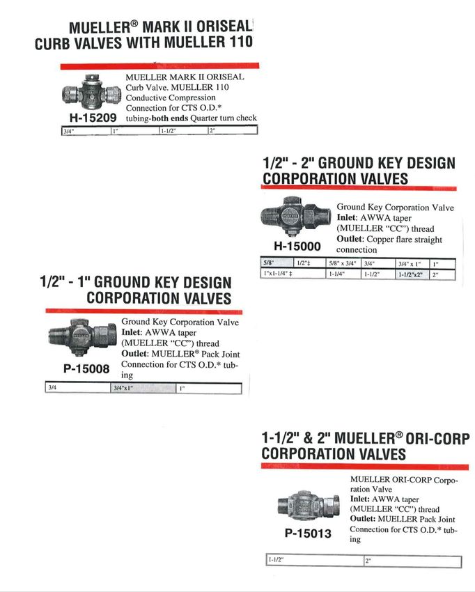
K.   TRACER WIRE – 12 AWG SOC 10 PE (COLOR-BLUE) or LARGER.

                               SECTION II – Potable Water Main Pipe
A.   CLASS 52 CEMENT LINE DUCTILE CAST IRON PIPE WITH PUSH ON JOINT – (ANSI A21.51, AWWA C151)

                                            Minimum Wall Thickness
                           6” - 0.31                                        20” - 0.42
                           8” - 0.33                                        24” - 0.44
                          10” - 0.35                                        30” - 0.47
                          12” - 0.37                                        36” - 0.53
                          14” - 0.39                                        42” - 0.59
                          16” - 0.40                                        44” - 0.65
                          18” - 0.41
               Table 2 – Class 52 Cement Line Cast Iron Pipe w/Push On Joint, Minimum Wall Thickness

                               SECTION III – Water Line Components
A.   DUCTILE IRON PIPE
      All ductile iron pipes shall meet the physical property recommendations of ASTM A536, “Ductile Iron
     Castings” with bell and spigot push on joints, complete with gaskets, and lubricants. Unless otherwise
     approved, the minimum thickness for the barrel of the pipe shall be thickness Class 52 for all trench
     installations and thickness Class 56 for railroad bore and jack installations. Pipe shall be cement lined
     inside with a bituminous coating in accordance with ANSI/AWWA A21.4/C104 and the outside shall be
     coated with a bituminous coating. The pipe shall be manufactured in strict accordance with
     ANSI/AWWA A21.51/C151. (Drawing PST 101)

B.   JOINTS
      Push-on and mechanical joints, including accessories shall conform to ANSI/AWWA A21.11/C111
     “Rubber Gasket Joints for Ductile Iron Pressure Pipe and Fittings”. Bolts shall be stainless steel Type
     316. Flanged joints shall not be used in underground installations without prior approval. (Drawing
     PST 101)

C.   DUCTILE IRON FITTINGS
     Ductile iron standard and special fittings shall conform to ANSI/AWWA A21.53/C153, “Ductile Iron
     Compact Fittings, 3 inches through 24 inches and 54 inches through 64 inches. “Fittings for 3 inch
     through 24 inch shall be suitable for 350 psi of pressure. The fittings shall be coated outside with a
     bituminous coating in accordance with ANSI/AWWA A21.53/C153 and lined inside with cement mortar
     and sealed coated in accordance with ANSI/AWWA A21.4/C104. (Drawing PST 501A)

D.   NUTS AND BOLTS
     All nuts and bolts added are required to be Stainless Steel Type # 316.

E.   TAPPING VALVE
     Tapping valves shall be all areas with MUELLER T-2360-16, BRONZE or equ, conforming to AWWA C509
     Standard. Tapping valve shall be of a cast ductile iron body and have an inlet flange on one end for
     bolting to the tapping sleeve and a mechanical joint type end connection. Tapping valve shall have a

                                                         4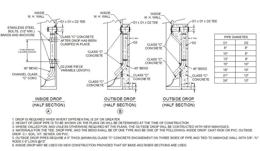
full sized resilient wedge, open left (counter clockwise), non-rising stem (NRS) and designed for a
     working pressure of 150 P.S.I.

F.   TAPPING SLEEVE
     Tapping sleeves shall be MUELLER H-615 (4” to 12” sizes 200PSI/14”-24” sizes-150PSI), ductile cast iron,
     AWWA approved, “mechanical joint ends ANSI/AWWA C111 or and stainless steel tapping sleeve (PST
     601) to assure uniform gasket pressure and permit centering of the sleeve on the pipe. Flange
     dimensions and drilling comply with ANSI B16.1 and MSS SP-60. (Drawing s PST 601 & PST 602)

G.   CORPORATION STOPS AND VALVES (3/4 “, 1”)
     Corporation stops and valves shall be Mueller H-15008, Ground Key Corporation Stop, ¾” to 1” with a
     conductive compression connection for CTS OD tubing pt Mueller H-15013 ORI-CORP Corporation
     Valve, 1 ½” to 2” with a conductive compression outlet connection for CTS OD tubing or Mueller H-
     15000 Ground Key Corporation Stop with a copper flare straight outlet connection. (Drawings PST 701
     & PST801)

H.   CURB STOPS AND VALVES
     Curb stops and valves shall be Mueller H-15209 with a conductive compression outlet connection for
     CTS OD tubing-all valves shall be left opening (counter- clockwise)-both ends Quarter turn check or
     Mueller H-15204 copper flare nut-both ends Quarter turn check (Drawings PST 701 & PST801)

I.   CURB VALVE BOX WITH ROD
     Curb valve boxes shall be Mueller H-10314 extension type with arch pattern base and shall be
     adjustable in height from 42 inches to 60 inches. Curb boxes shall have one piece lids with two holes
     for 1” services or two piece lids with brass pentagon plug for 2” services and shall have the word
     “WATER” cast neatly on the lid (Drawings PST 1101 and PST 1201)

J.   ROADWAY VALVE BOX
     Valve boxes shall be genuine buffalo style cast iron, size No. 22 (Series 6850), adjustable screw type
     with 5 ½ “shaft and of such length to extend from valve to finished grade, five foot bury. Valve box
     covers shall be marked “WATER”. (Drawing PST 1301)

K.   GATE VALVE
     Gate valves shall be either double disc Mueller A-2380-20 or resilient seat wedge Mueller A2360-20
     complying with AWWA C509. All gate valves shall have a non-rising stem (NRS) with rubber “O” ring
     packing seals and shall be furnished with mechanical joints unless otherwise specified. All resilient
     seated gate valves shall be designed for 400 P.S.I. test pressure and a maximum working pressure of
     200 psi with no leakage, unless otherwise noted. All valves shall be installed in a vertical position and
     open by turning to the left (counterclockwise). Stainless steel Type 316 bolts and nuts shall be used.
     (PST 1501-PST 2001).

L.   FIRE HYDRANTS
     Fire hydrants shall be first line hydrants and shall conform as a minimum to the American Water Works
     Association standard C502, latest revision thereof. Hydrants shall be Mueller Super Centurion No. A-
     423. Hydrants shall be compression main valve type of the center stem construction, closing with the
     line pressure and shall be designed for a working pressure of 150 PSI in ordinary water works service.
     Fire Hydrants shall meet the following specifications (Drawings #PST 2010 and PST 2201):

     1.      Inlet Connection
                     The inlet shall be a 6-inch bell end connection suitable for a mechanical or push-on
                     joint of Class 52 ductile iron spigot end pipe.

                                                     5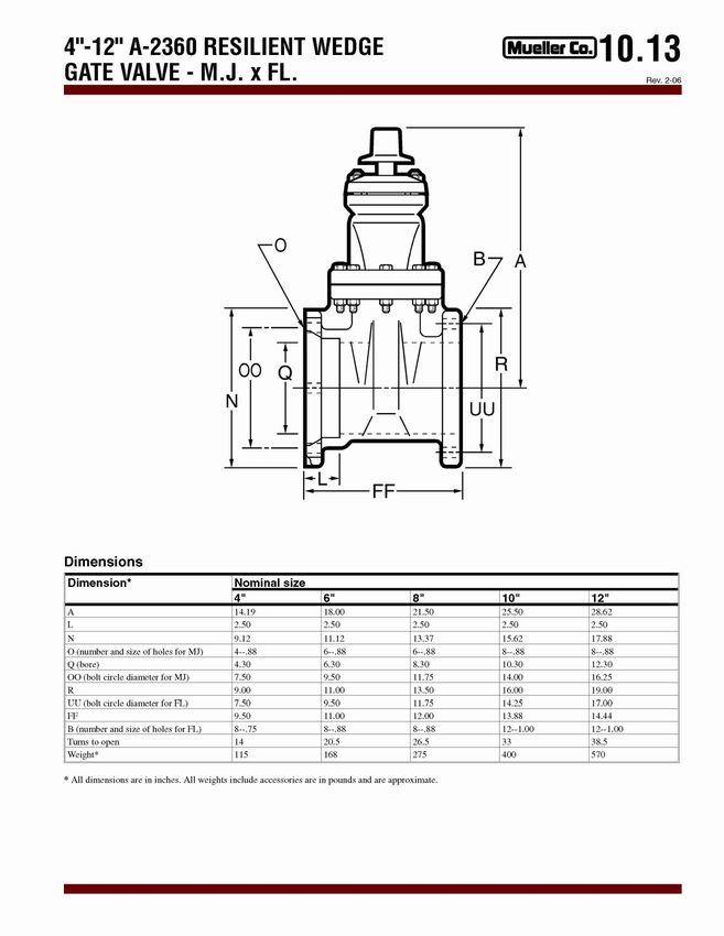
2.   Hoses and Nozzles
            Each hydrant shall have two 2 ½ inch hose nozzles and one 4 ½ inch bronze pumper
            nozzle. Hydrants shall be furnished with a five foot bury line and shall be self-draining.
            The hydrants shall open by turning left (counterclockwise). The equipment shall be
            new and all applicable warranties shall be submitted to the Village upon delivery.

3.   Mueller No. A-423 Centurion Fire Hydrant Main Valve and Seat Ring
            All hydrants shall have a main valve opening of at least 5 ¼ inches in diameter. The
            valve gasket shall be of synthetic rubber at least 1 inch thick. The design of the main
            valve assembly shall be such that, the main valve and seat ring may be removed from
            above ground by a wrench through the upper barrel without excavation. The bronze
            seat ring shall thread directly into a bronze drain ring forming an all bronze waterway.
            All bronze internal parts shall be ASTM B-62 grade. All pressure seals shall be
            accomplished by the use of “O” ring seals.

     3a.     Hydrant Barrel
                   The lower barrel shall be a one piece casting with integrally cast lower and
                   upper flanges.

                     The design of the hydrant shoe shall be such that it may be removed from the
                     lower barrel without disturbing the main valve seal. The lower barrel shall also
                     be removable from the shoe without disturbing the main valve seal. The shoe
                     shall be contoured smoothly to assure maximum flow. The interior of the shoe
                     shall be coated with a two-part, non-toxic, thermo-setting epoxy. The coating
                     shall be formulated from materials deemed acceptable per Food and Drug
                     Administration Document Title 21, Section 121.2514, resins and polymeric
                     coatings. The inlet connection of the hydrant shoe shall be six (6) inch
                     mechanical joint.

                     A two-part safety flange shall accomplish the connection of the upper barrel to
                     the lower barrel. The upper barrel shall be capable of rotating a full 360o
                     without full disassembly at the ground line.

     3b.     Valve and Drain Stem
                    The main valve stem shall be a two-piece design joined at the safety flange
                    area by a steel torque-diverting coupling. The coupling shall be affixed to the
                    main valve stem by means of stainless steel clevis pins and stainless steel cotter
                    pins. The main valve stem in the lower barrel shall be coated with a two-part,
                    non-toxic epoxy. The coating shall be formulated from materials deemed
                    acceptable per Food and Drug Administration Document Title 21, Section
                    121.2514, resins and polymeric coatings. The hydrants shall have double drain
                    valves to facilitate complete drainage of the barrel.

                     The bonnet section shall be constructed of a one-piece casting and shall have a
                     seal oil reservoir as an integral part. The oil reservoir will be such that it has
                     two “O” ring seals at the bottom, one serving as a pressure seal, the other as a
                     dirt seal. There shall also be “O” ring seals between the bronze hold down nut
                     and the bonnet, between the hold down nut and the operating nut. The oil
                     reservoir will be such that the oil is recycled and all working parts in the bonnet
                     section are lubricated each time the hydrants is fully opened and closed. The
                     one piece operating nut will be such that there is an anti-friction washer above

                                             6
the thrust collar to reduce operating torque and decrease wear. Attached to
the operating nut there shall be a ductile iron weather cap.
4. Detailed Specifications
One 2 ½ inch hose nozzle rated at 250 GPM (0.25 P.S.I. Pressure Loss)
Two 2 ½ inch hose nozzle rated at 500 GPM (1.00 P.S.I. Pressure Loss)
One 4 ½ inch steamer nozzle rate at 1,000 GPM (2.20 P.S.I. Pressure Loss)
Size of main valve opening 5 ¼ inches
Size of inlet 6 inches
Type of inlet Mechanical joint with accessories
Hose nozzles 2 – 2 ½ inches
Steamer nozzles 1 – 4 ½ inches
Hose nozzle threads National Standard 3.0686 O.D. & 7 ½ T.P.I.
Steamer nozzle threads National Standard 5.7609 O.D. X 4 T.P.I.
Size and shape of operating nut 1 ½ inch pentagon
Direction of opening Left
Depth of bury 5 feet
M. APPROVAL
All products shall be approved by the Village of Burton prior to installation.
7Mechanical Joint Fittings
Valve and Hydrant Connecting Pieces
Figure 1- Mechanical Joint Fittings # PST 501A
8Figure 2- Joint Tapping Sleeve # PST601
9Figure 3-Stainless Steel Tapping Sleeve 4" - 24", PST # 601A
10Figure 4 - Curb and Corporation Valves . PST # 701
11Figure 5 - Curb Valves w/Copper Flare Connection, PST # 801
12Figure 6- Curb Boxes-Improved Ext Type with Arch, PST # 1101
13Figure 7 - Cub Boxes - Extension Type with Arch, PST 1201
14Figure 8 - Screw Type Valve Box Detail, PST 1301
15Figure 9 - A-2360 2" - 12" Resilient Wedge Gate Valve- M.J. X M.J. , PST # 1601
16Figure 10 - Mueller 260 Series Resilient Wedge Gate Valve, PST # 1701
17Figure 11 - A-2360 , 4"-12" Resilient Wedge Gate Valve - M.J. X FL., PST 1801
18Figure 12 - A-2360, 2"-12" Resilient Wedge Gate Valves - M.J. X M.J., PST # 2001
19Figure 13 – Mueller Super Centurion Fire Hydrant, PST # 2101
20Figure 14 - Mueller Super Centurion Fire Hydrant, PST # 2201
21SECTION IV – Remote Water Meter Installation
This specification is the installation of residential 5/8-inch X ¾ inch remote water meters. All commercial and
industrial meters must be approved on an individual basis as per the General Rules and Regulations of the
Water Division. All meter installations shall be planned and constructed for remote reading devices. The
owner or contractor is responsible for contacting the Burton Utilities so that the remote wire installation can be
made prior to enclosing walls, ceilings, etc.
A. GENERAL SPECIFICATIONS
(a) Meter installation, location and maintenance.
i. All meters are to be kept free from rubbish, debris or anything else preventing reasonable
access by the Village or its agents.
ii. All water meters are to be installed and maintained in an area free of temperature extremes,
to specifically include insulation from frost or possible freezing damage. Owner shall provide
notice to the Board of any damaged or inoperable water meter. If it is necessary to repair or
replace a water meter due to damage caused by Owner, its tenants, or agents, then the
Owner shall bear all expenses for the repair or replacement, including all labor and material
expended by the Village at a rate of one hundred thirty percent (130%) of the Utilities
Operator’s hourly rate based upon the maximum salary of the position, with a minimum of
one-half hour charge.
iii. The Village may install remote water meters for the purpose of facilitating water meter
readings by Village personnel. The remote water meters shall be installed at the Village’s
expense and all remote reading technology (including software licenses) and remote reading
equipment shall be maintained by the Village at its sole cost.
Meter pits, if permitted, are required to have approval of the Director. If approved, meter pits shall
meet the specifications of the utility and be furnished, owned and maintained by the consumer. Water
meters shall be installed as follows:
*Reference next page for Meter Instruction Drawing (# PST 2301)
B. WATER METER INSTALLATION IN OUTSIDE PIT
1. Meter pit cannot be under trailer.
2. Meter pit must be accessible at all times.
3. Box must be kept in good repair at all times.
4. Meter pit may be made of treated wood or equivalent wood with minimum thickness of 1 inch
and insulate with 2-inch-thick Styrofoam or a manufactured Mueller/McCullough meter vault
(for approved equal). Lid must be a removable cover with an opening size no smaller than 20
inches by 28 inches. (Drawing # PST 2250)
225. Meter pits located in low or wet areas must be designed to prevent water from filling pit.
6. Pipe from pit should be at least 34 inches underground or if above ground must be insulated so
as not to freeze. That part of the service line that will be outside shall have heat tape running
from the “in” side of the meter to the trailer with a fiberglass wrap (with windbreaker wrap on
outside) from inside the box to the point of attachment to trailer.
7. Pit must have enough heat either from soil or heat tape (with thermostat or limit so as not to
damage meter) to keep from freezing in winter. All meters damaged by freezing will be
repaired or replaced at customer’s expense.
8. All water meters shall have a solid electrical bonding “jumper” placed around them,
conforming to the National Electric Code (N.E.C.) and all other applicable standards and
regulations, unless the structure is served by a non-metallic water line.
*for Meter Pit reference (Drawer # PST 2401)
Figure 15 – Meter Pit Drawing, PST # 2250
23Figure 16 - Meter Instruction Drawing, PST # 2301
DRAWING # PST 2401
24Figure 17 - Meter Pit Drawing with Detail, PST # 2401
25SECTION V – Hydrostatic Water Line Testing
Ref: AWWA C-600-82, AWWA C-601
The developer of his contractor shall perform hydrostatic water line testing in accordance with A.W.W.A.
Standard C-600-82 specified herein. Air pressure testing may be used to isolate problems but is not acceptable
for final approval of water lines by the Burton Utilities. The developer or his contractor shall provide gauges for
pressure tests. All water used for water line testing supplied from the Village water supply is at the expense of
the developer.
A. PRESSURE TEST
1. Test Pressure
All newly laid pipe or any valved section thereof shall be subjected to a hydrostatic pressure of
at least 1.5 times the working pressure at the point of testing.
2. Restrictions
Test pressures shall:
2a. Not be less than 1.25 times the working pressure at the highest point along the test
section.
2b. Not exceed pipe or thrust-restraint design pressures.
2c. Be of at least a 2-hour duration.
2d. Not vary by more than +-5 psi (0.35 Bar) for the duration of the test.
2e. Not exceed twice the rated pressure of the valves or hydrants when the pressure
boundary of the test section includes closed gate valves or hydrants. Note: Valves
shall not be operated in either direction or differential pressure exceeding the rated
pressure.
2f. Not exceed the rated pressure of the valves when the pressure boundary of the test
section includes closed resilient-seated gate valves or butterfly valves.
3. Pressurization
Each valved section of pipe shall be filled slowly with water and the specified test pressure shall
be applied by means of a pump connected to the pipe in a manner satisfactory to the owner.
The test pressure shall be based on the elevation of the lowest point of the line or section
under test and corrected to the elevation of the test gauge. Valves shall not be operated in
either the opening or closing direction at differential pressures above the rated pressure. It is
good practice to allow the system to stabilize at the test pressure before conducting the
leakage test.
4. Air Removal
Before applying the specified test pressure, air shall be expelled completely from the pipe,
valves, and hydrants. If permanent air vents are not located at all high points, the contractor
shall install corporation cocks at such points so that the air can be expelled as the line is filled
with water. After all the air has been expelled, the corporation cocks shall be closed and the
test pressure applied. At the conclusion of the pressure test, the corporation cocks shall be
removed and plugged or left in place at the discretion of the Village.
26B. LEAKAGE TEST
The leakage test shall be conducted concurrently with the pressure test.
1. Leakage Defined
Leakage shall be defined as the quantity of water that must be supplied into the newly laid
pipe, or any valved section thereof, to maintain pressure within five (5) psi (0.35 Bar) of the
specified test pressure after the air in the pipeline has been expelled and the pipe has been
filled with water. Leakage shall not be measured by a drop in pressure in a test section over a
period of time.
2. Allowable Leakage
No pipe installation will be accepted if the leakage is greater than that determined by the
following formula:
L = SDP
133200
In which L is the allowable leakage, in gallons per hour; S is the length of pipe tested, in feet; D
is the nominal diameter of the pipe, in inches; and P is the average test pressure during the
leakage test, in pounds per square inch gauge. In metric units.
Lm = SDP
2816
In which Lm is the allowable leakage, in liters per hour; S is the length of the pipe tested, in
meters; D is the nominal diameter of the pipe in inches; and Pis the test pressure in Bars.
These formulas are based on an allowable leakage of 11.65 gpd, per mile, per inch nominal
diameter at a pressure of 150 psi.
3. Allowable Leakage at Various Pressures
Allowable leakage at various pressures is shown in Table 6.
Allowable Leakage per 1000 ft (305 m) of Pipeline
Nominal Pipe Diameter - Inches
Average Test
Pressure PSI 3 4 6 8 10 12 14 16 18 20 24
(Bar)
250 (17) .36 .47 .71 .95 1.19 1.42 1.66 1.90 2.14 2.37 2.85
225 (16) .34 .45 .68 .90 1.13 1.35 1.58 1.80 2.03 2.25 2.70
200 (14) .32 .43 .64 .85 1.06 1.28 1.48 1.70 1.91 2.12 2.55
175 (12) .30 .40 .59 .80 .99 1.19 1.39 1.59 1.79 1.98 2.38
150 (10) .28 .37 .55 .74 .92 1.10 1.29 1.47 1.66 1.84 2.21
125 ( 9) .25 .34 .50 .67 .84 1.01 1.18 1.34 1.51 1.68 2.01
100 (7) .23 .30 .45 .60 .75 .90 1.05 1.20 1.35 1.50 1.80
Table 3 - Nominal Pipe Diameter
27*-If the pipeline under test contains sections of various diameters, the allowable leakage will be the sum of the
computed leakage for each size.
# - To obtain leakage in liters/hour, multiply the values in the table by 3.785.
4. When testing against closed metal-seated valves, an additional leakage per closed valve of
0.0078gal/h/in. (0.0012 L/h/mm) of nominal valve size shall be allowed.
5. When hydrants are in the test section, the test shall be made against the closed hydrant.
6. Acceptance of installation: Acceptance shall be determined on the basis of allowable leakage.
If any pipe laid discloses leakage greater than that specified in Section II.B., the contractor shall,
at this own expense, locate and make repairs as necessary until the leakage is within the
specified allowance.
7. All visible leaks are to be repaired regardless of the amount of leakage.
C. DISINFECTION
1. Newly installed or repaired water main shall be disinfected in accordance with AWWA C651
Standards. The forms of chlorine that may be used are liquid chlorine, sodium hypochlorite
and calcium hypochlorite granules or tablets using the continuous feed, slug or tablet method.
The continuous feed method is the most suitable for general applications. Following
chlorination, the main should be flushed as soon as possible since prolonged exposure to high
concentrations of chlorine might damage the asphaltic seal coat.
BASIC DISINFECTION PROCEDURE
The basic disinfection procedure consists of:
a. Inspecting all materials to be used to ensure the integrity of the materials.
b. Preventing contaminating materials from entering the water main during storage, construction
or repair and noting potential contamination at the construction site.
c. Removing by flushing or other means, those materials that may have entered the water main.
d. Chlorinating any residual contamination that may remain and flushing the chlorinated water
from the main.
e. Protecting the existing distribution system from backflow caused by hydrostatic pressure test
and disinfection procedures.
f. Documenting that an adequate level of chlorine contacted each pipe to provide disinfection.
g. Determining the bacteriological quality by laboratory test after disinfection.
h. Final connection of the approved new water main to the active distribution system.
28Upon filling of the water mains, the potable water shall be chlorinated so that after a 24 hours holding
period in the main there will be a free chlorine residual of not less than 10 mg/l. After the holding
period the heavily chlorinated water shall be flushed from the main until chlorine measurements show
the concentration in the water leaving the main is below 2 mg/l. After flushing and before the new
water is connected to the distributions system, two consecutive sets of acceptable samples, taken at
least 24 hours apart, shall be collected from a sampling tap. No hose or fire hydrant shall be used in
the collection of samples.
All samples shall be tested for bacteriological quality in accordance with Standard Methods for
Examination of Water and Wastewater; and shall show the absence of coliform organisms. If the initial
disinfection fails to produce satisfactory bacteriological results, the new main may be reflushed and
shall be resampled. If check samples also fail, the main shall be rechlorinated by the continuous feed or
slug method until satisfactory results are obtained. (You may use the above method or other AWWA
approved disinfection methods).
29SEWER SECTION 30
SEWER - GENERAL PIPE REGULATIONS

1.   All Iron and steel products use for the construction alteration maintenance for repair of water systems
     or treatment works are to be AIS compliant and products that are produced in the United States. The
     American Iron and Steel (AIS) provision of the 2014 Consolidated Appropriations Act requires Clean
     Water State Revolving Fund (CWSRF) and Drinking Water State Revolving Fund (DWSRF) assistance
     recipients to use iron and steel products that are produced in the United States. This requirement applies
     to projects for the construction, alteration, maintenance, or repair of a public water system or public
     treatment works, unless a waiver is granted or 1 of 3 of the following exceptions applies (non-availability,
     unreasonable cost or inconsistent with the public interest).”

2.   All sewer lines shall be installed with a minimum of four (4) feet of cover.

3.   Sizing of sanitary sewer mains to accommodate future growth shall be determined by Burton Utilities.

4.   All costs for sewer system improvements, including necessary over-sizing, shall be borne by the
     developer.

5.   All sewer mains shall be extended to the farthest property line of the developer to accommodate
     future growth. Said main extensions shall be at the expense of the developer.

6.   All sewer installations shall be bedded in, and backfilled to 12 inches above the pipe with #57 bank run
     wash gravel or crushed stone. All trenches under paved areas shall be backfilled and properly
     compacted to finished grade with #411/304 limestone.

7.   All sewer pipes, fittings, manholes, manhole castings, and lids, meter pits and other appurtenances and
     incidentals shall conform to specifications and standards as specified in the “WATER & SEWER PIPE
     STANDARDS” for the Burton Utilities.

8.   All sanitary sewer service laterals from the main to the building shall be SDR 35 pipe conforming to
     ASTM D3034 material specification and ASTM D 3212 joint specification. Said sanitary sewer shall be a
     minimum of six (6) inches in diameter and installed with a minimum slope of one (1) percent. Where
     an existing four (4) inch “Y” branch is found, and deemed serviceable by the Village, the building sewer
     may be four (4) inches in diameter and installed with a minimum slope of two (2) percent.

9.   All gravity sanitary sewer mains to be maintained by the Village shall be a minimum of eight (8) inches
     in diameter and be PVC pipe conforming to ASTM D3034 material specification and ASTM D 3212 joint
     specification of ASTM F 1803 and F949.

     PVC gravity sanitary sewer pipe and fittings confirming to ASTM D3034 shall be allowed for sanitary
     sewers when the depth of cover is greater than four (4) feet and no more than twenty (20) feet and
     when the internal pipe diameter is less than or equal to ten (10) inches.

     PVC gravity sanitary sewer pipe and fittings conforming to ASTM F 1803 and F949 shall be allowed for
     sanitary sewers greater than ten (10) inches in internal diameter and greater than twenty feet (20) in
     depth.

                                                     31
10. Force main sanitary sewers shall be constructed of Class 52 cement lined ductile cast iron pipe or PVC
pipe and fittings, which shall conform to ASTM D2241, SDR21, 200 psi. They shall be a minimum of two
(2) inches in diameter and have a minimum of four (4) feet of cover.
11. A manufacturer certificate that the pipe and fittings were manufactured and tested in accordance with
the appropriate ASTM specification must accompany all PVC pipes and fittings. Said certificate shall be
submitted to the Burton Utilities prior to the installation of said pipe.
12. All sanitary sewer manholes installed in, or tributary to, the Village of Burton sanitary sewer system
shall be precast concrete meeting ASTM C-478 material specification an dASTM C-443 joint
specification. They shall be installed at a maximum of 300 feet apart and at the end of all sewer mains
and in changes in sewer line direction greater than 15 degrees.
13. All sanitary sewer manholes to be maintained by the Burton shall be covered with Neenah R-1787 or
1785 manhole frame and lid as per Section VI herein. (TABLE 11).
14. Grease traps must be installed according to Geauga County Health Department specifications when
required. Detailed drawing of minimum design requirements attached. (Reference next page for
drawing # PST 2401A).
32Figure 18- 500 Gallon Grease Trap, PST # 2401A (1 of 2)
Figure 19 – Grease Trap Interceptor, PST # 2401 A (2 of 2)
33SECTION VI – Sanitary Sewer Pipe
SANITARY SEWER PIPE (GRAVITY)
MATERIAL JOINT
SPECIFICATION SPECIFICATION
A. VITIRIFIED CLAY SEWER MAINS AND LATERALS ASTM C- 700 ASTM C – 425
B. TYPE PSM POLYVINYL CHLORIDE (PVC) ASTM D – 3034 ASTM D – 3212
C. MAIN LATERAL SEWER PIPE < 18 INCHES
D. PVC SANITARY SEWER & FITTINGS > 18 INCHES ASTM F – 1803
ASTM F - 949
Table 4 - Sanitary Sewer Pipe (Gravity)
Minimum Wall Thickness
4 “ - .120
6” - .180
8” - .240
10” - .300
12” - .360
15” - .437
Table 5 - Minimum Wall Thickness - Sanitary Sewer Pipe
SANITARY SEWER FORCE MAIN PIPE
A. POLYVINYL CHLORIDE (PVC) PIPE, SDR – 21 ASTM D – 2241
B. POLYVINYL CHLORIDE PRESSURE PIPE AWWA C – 900
C. CLASS 52 DUCTILE CAST IRON PIPE ANSI – A21.51
Table 6 - Sanitary Sewer Force Main Pipes
SANITARY SEWER MANHOLES, CASTINGS & LIDS
MATERIAL JOINT
SPECIFICATION SPECIFICATION
A. PRESCAST CONCRETE SANITARY SEWER MANHOLES ASTM C – 478 ASTM C - 443
B. MANHOLE FRAMES & LIDS, NEENAH R-1762 WITH
SOLID LID, TOTAL WEIGHT 350 LBS.
Table 7 - Sanitary Sewer Manholes, Castings & Lids
34SECTION VII – Specifications for Manhole Frames, Lids and Adjusting Rings
This specification is for Ferrous Castings. Materials used in the manufacture of castings shall conform to ASTM,
AASHTO, ASA, MIL, AMS or Federal Specifications for Gray Iron or other applicable standards. They shall be of
uniform quality, free from blowholes, porosity, hard spots, shrinkage distortion or other defects. They shall be
smooth and well cleaned by shot blasting. They shall be coated with asphalt paint, which shall result in a
smooth coating, tough and tenacious when cold, not tacky and brittle.
A. GENERAL SPECIFICATIONS
All castings shall be manufactured true to pattern; component parts shall fit together in a satisfactory
manner. Round frames and covers shall have machined bearing surfaces to prevent rocking and
rattling under traffic. As a minimum, the castings shall conform to ASTM A 48, Class 30 with tensile
strength 30,000 pounds per square inch.
The lids shall have cast in them for identification, the words SANITARY SEWER.
Figure 20 - Sanitary Cast Iron Lids, PST # 2501
35B. SUPPLIERS OF MANHOLE FRAMES AND LIDS
Suppliers include the following:
NAMES OF SUPPLIER NUMBER - FRAME A ND LID
Nennah Foundry R-1787 4 ½” rise
East Jordan Iron Works R-1785 9“ rise
Item 1 – Manhole Frame with Solid Lid, Total Weight 350 lbs.
Table 8 - Suppliers of Manhole Frames and Lids
C. MANHOLE RISERS
Manhole risers shall be one of the adjustable type or solid type and must be fitted properly to the
existing casting and lid. Riser rings shall consist of domestic A-36 steel ¾” thickness steel inner and
domestic A-36 steel ½” thickness outer ring. Certified welders shall perform all welds in accordance
with AWS D1.5 Bridge Code. The riser ring shall be anchored to the manhole frame to prevent any
movement from traffic loads with (3) 1/2" # 5 cone head set screws or bolts. The adjustment device
shall be fabricated from stainless steel, shall be capable of adjustment +/-3/8” from nominal. The
manhole adjustment ring shall fit within the existing casting without interference and the manhole lid
shall have bearing on all the surface of the inner ring to prevent rocking from occurring. The lid shall be
removable without binding. The inner and outer ring shall be securely welded to prevent any
differential movement between the inner and outer rings under traffic loads and shall be fabricated to
+/- 1/16” concentricity. The outer riser shall have an inside diameter no greater than 3/16” larger than
the outside diameter of the manhole lid and shall not be greater than 4” in height. All materials shall
be bituminous asphalt coated. (See Next Page for Drawing # PST 2601).
All grade adjustments using riser rings shall be approved by the Village and fit properly. No more than
2 adjusting rings may be used per manhole frame.
SECTION VIII – Specification for Sanitary Sewer Drop Manholes
This specification is for sanitary sewer drop manholes. Drop manholes may be installed in, or tributary to, the
Village of Burton sanitary sewer system, only when approved by the Department of Public Utilities. They shall
conform to design criteria contained therein.
Drop manholes shall not be utilized for immediate changes in sewer elevation of less than two (2) feet. The
drop pipe shall be, as a minimum, 8” in diameter but it shall not be of lesser diameter than the influent line,
which it serves.
For manholes constructed prior to January 1, 1981, which are served an effluent line with a diameter smaller
than 8”, the Burton Utilities may consider influent lines and drop pipes of less than 8” diameter but not less
than the diameter of the effluent line.
Installation of drop manhole installations shall be in the presence of a qualified inspector designated by the
Department of Public Utilities.
Drop manholes are used to provide for significant changes in grade or elevation resulting from the topography
of the area. These structures should be used as infrequently as possible since they are a source of high
36turbulence in sewage flow. Where hydrogen sulfide gas (H2S) is present in sewage, agitation turbulence
developed by drop manhole can cause the H2S gas to be released, resulting in severe odor problems and
corrosion of the manhole structure.
Two types of drop manholes are currently accepted.
1) Inside drop manholes (Drawing # PST 2701, item A)
2) Outside drop manholes (Drawing # PST 2701, item B)
The inside drop is the preferred method because of its economic and maintenance benefits. Reference
Drawing # PST 2701
Figure 21 - Sanitary Sewer Drop Manholes, PST # 2701
37SECTION IX – Service Connections
A. PLANNED SERVICE CONNECTIONS
All service connections, installed as a part of new sanitary sewer main installation, shall be by means of
an approved tee, a minimum of six (6) inches in internal diameter. Said service connection shall be
extended a minimum of three (3) feet into the property to be served, capped watertight, and the
termination location indicated by a treated 2 X 2 marker extended a minimum of one foot above
finished grade.
B. UNPLANNED SERVICE CONNECTIONS
All unplanned service connection methods must be approved by the Inspector and are at the expense
of the Contractor. They shall be made in the field under observation of the Inspector. Service saddles
may be installed, either gasketed and clamped or solvent cemented. When a field cut-in service
connection is required, the following precautions should be observed.
1. Carefully cut the opening for the type of fitting to be used.
2. Prevent entrance of foreign material info cut-in pipe opening.
3. Use proper fitting and procedure for installing the field connection.
4. After curing for 24 hours, bed and backfill properly all pipe and fittings. (Note: Solvent welded
fittings will gain 50% of full strength after 24 hours of curing time.)
5. Be sure and use ASTM D3034 saddles. Do not confuse with D3033.
C. CONNECTIONS
Connections to pipe of different materials shall be made with approved adapters. For taps into all
known approved solid wall, profile and closed profile pipe. INSERT TEE fittings, shall be used.
Installation must be made according to INSERTA FITTINGS CO. installation procedures and using
approved lubricants. (Reference next Drawing # PST 2801).
D. INSERTA-TEE INSTALLATION PROCEDURE
Use Hole Saw Core Bits for PVC, Ribbed, and Polyethylene pipe. Use Diamond Core Bits for Concrete, Clay, D.I.
and Fiberglass Pipe.
TOOLS REQUIRED
1. Hand held drill with hole saws recommended for 4”, 6”, & 8” INSERTA TEES. Tie down coring
machine recommended for 10” X 12” INSERTA TEES and all diamond bits.
2. BITS INSERTA TEE size Bit (hole) Diameter
4” 4 ½”
6” 6 ½”
8” 8 ¾”
10” 10 7/8”
12” 12 7/8”
15” 15 13/16”
3. 6 lb. Hammer and 2” X 4” board.
4. Bottle of INSERTA TEE solution supplied with order.
38You can also read