Yb-Doped Fiber Chirped Pulse Amplification System Delivering 1 mJ, 231 fs at 1 kHz Repetition Rate
←
→
Page content transcription
If your browser does not render page correctly, please read the page content below
hv
               photonics

Communication
Yb-Doped Fiber Chirped Pulse Amplification System
Delivering 1 mJ, 231 fs at 1 kHz Repetition Rate
Haitao Zhang *, Jiaqi Zu, Decai Deng                    , Haozhen Xu and Junyu Chen

                                          Center for Photonics and Electronics, Department of Precision Instrument, Key Laboratory of Photonic Control
                                          Technology, Tsinghua University, Beijing 100084, China; zujiaqi218@126.com (J.Z.); decaideng@gmail.com (D.D.);
                                          haozhenxu31@gmail.com (H.X.); jy-chen20@mails.tsinghua.edu.cn (J.C.)
                                          * Correspondence: zhanghaitao@mail.tsinghua.edu.cn

                                          Abstract: In this paper a single-channel chirped pulse amplification laser system based on Yb-doped
                                          photonic crystal fiber was constructed, which achieved a pulse energy output of 1 mJ with a beam
                                          quality close to the diffraction limit. Pulsed synchronous pumping was used to suppress amplified
                                          spontaneous emission at a repetition rate of 1 kHz. The de-chirped pulse width of 231 fs was achieved
                                          by precise systematic dispersion control, and the corresponding peak power reached 3.85 GW.

                                          Keywords: femtosecond fiber laser; chirped pulse amplification; high energy; synchronously
                                          pumping technology

                                          1. Introduction
                                                High energy femtosecond lasers are widely used in many industrial and academic
                                          fields [1–3]. In industry, femtosecond lasers have become mature instruments in material
                                          processing and surgical units. In academia, it has been an enabling tool in many time-

                                   resolved fields, including 2D spectroscopy, transient absorption spectroscopy and ultra-
Citation: Zhang, H.; Zu, J.; Deng, D.;    fast electron diffraction [4–6]. In addition, the short pulse width and high peak power
Xu, H.; Chen, J. Yb-Doped Fiber           of femtosecond pulses are the key to driving nonlinear optical processes. For example,
Chirped Pulse Amplification System        high energy physics, such as laser particle acceleration [7], requires femtosecond pulses
Delivering 1 mJ, 231 fs at 1 kHz          with high peak power and large energy. On the one hand, in order to obtain such required
Repetition Rate. Photonics 2022, 9, 67.   output parameters, fiber femtosecond lasers are widely acclaimed for their high average
https://doi.org/10.3390/                  power capability, relatively simple setup, and excellent beam quality. On the other hand,
photonics9020067                          the combination of chirped pulse amplification (CPA) [8] and large mode area (LMA) fiber
Received: 29 December 2021
                                          solutions [9,10] can significantly improve the achievable performance. Their potential
Accepted: 21 January 2022
                                          has been well exploited in the past few decades. At present, the average power of the
Published: 27 January 2022
                                          femtosecond fiber laser can be kilowatt level and the beam quality approximates the
                                          diffraction limit [11]. However, extracting ultra-short laser pulses with a high peak power
Publisher’s Note: MDPI stays neutral
                                          is significantly more challenging than bulk laser systems because the high intensity in
with regard to jurisdictional claims in
                                          the fiber core lasts for a fairly long interaction time, which leads to nonlinear distortions
published maps and institutional affil-
                                          of pulse mainly caused by self-phase modulation (SPM). The high pump absorption of
iations.
                                          ytterbium doped fibers (YDF) results in a rather short amplifier design, which helps to
                                          reduce nonlinear phase accumulation. Fiber CPA systems using a Yb-doped LMA step-
                                          index fiber as the main amplifier with a pulse energy of more than several 100 µJ was
Copyright: © 2022 by the authors.
                                          proposed many years ago [12,13]. In order to further reduce nonlinearity, it is necessary to
Licensee MDPI, Basel, Switzerland.        increase the area of the mode field in fiber amplifiers. The increase of core size results in
This article is an open access article    the loss of single-mode behavior of the amplifier. For flexible fibers, the higher modes can
distributed under the terms and           be suppressed by the correct pattern matching of seed injection and the appropriate bend
conditions of the Creative Commons        fiber. Another solution is to use very large core, rod-type fibers, and suppress higher-order
Attribution (CC BY) license (https://     modes by using photonic crystal arrays. Photonic crystal fiber (PCF) amplifiers have been
creativecommons.org/licenses/by/          successfully used in systems with high pulse energy [14–16]. Eidam et al. realized the
4.0/).                                    output result of a single pulse energy of 2.2 mJ and a compressed pulse width of 480 fs

Photonics 2022, 9, 67. https://doi.org/10.3390/photonics9020067                                             https://www.mdpi.com/journal/photonics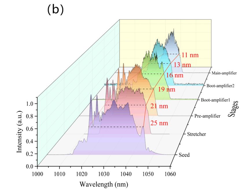
Photonics 2022, 9, x FOR PEER REVIEW                                                                                                2 of 8

Photonics 2022, 9, 67                                                                                                                      2 of 8

                                  been successfully used in systems with high pulse energy [14–16]. Eidam et al. realized
                                  the output result of a single pulse energy of 2.2 mJ and a compressed pulse width of 480
                                   bybyusing
                                  fs     usingaalarge-pitch
                                                 large-pitch PCF     [17], but
                                                              PCF [17],    butititintroduced
                                                                                   introducedmanymany     space
                                                                                                       space      elements,
                                                                                                               elements,       which
                                                                                                                           which       reduced
                                                                                                                                   reduced
                                  the reliability of the system. Moreover, the accumulated nonlinear effects worsened the the
                                   the reliability  of the system.     Moreover,    the  accumulated       nonlinear    effects  worsened
                                   compressionquality.
                                  compression       quality.  Although
                                                           Although         a narrower
                                                                       a narrower    pulsepulse
                                                                                            widthwidth
                                                                                                    (
Photonics 2022, 9, x FOR PEER REVIEW 3 of 8
repetition rate drop, synchronous pumping and autocorrelator detection. The remaining
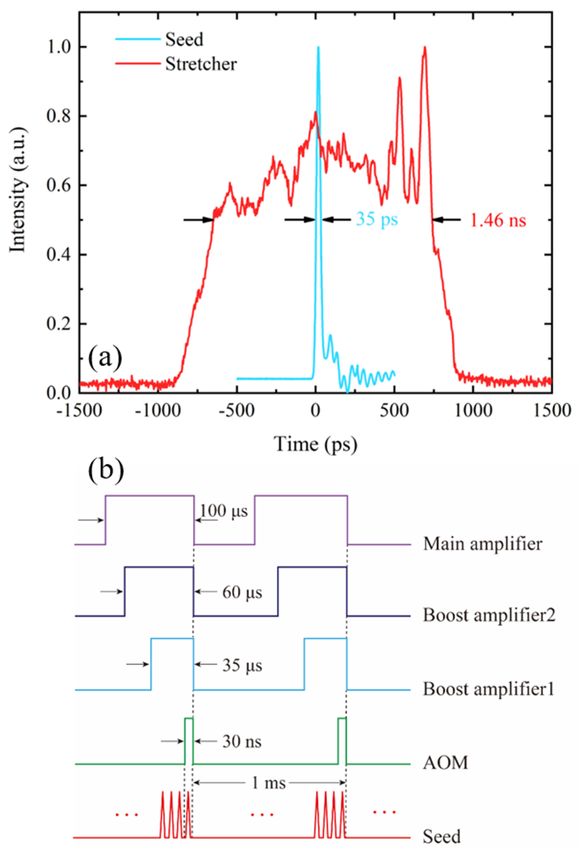
98 percent of the seed light was injected into the stretcher, where dual CFBG with a band-
Photonics 2022, 9, 67 3 of 8
width of 24 nm was applied. The group velocity dispersion (GVD) and third-order dis-
persion (TOD) it provided were 39.83 ps2 and −0.59 ps3, respectively. The seed pulse was
stretched from 35 ps to 1.46 ns, as shown in Figure 2a. The loss of the CFBG and the optical
dispersion
circulator was(TOD) it providedby
compensated were 39.83
a stage of ps2 and −0.59inps3,
preamplifier, respectively.
which the 0.5 m The
longseed
gain pulse
fiber,
was
highly Yb-doped single-mode fiber (PM-HI-YSF), was continuously pumped with 1 the
stretched from 35 ps to 1.46 ns, as shown in Figure 2a. The loss of the CFBG and W,
optical
976 nmcirculator
laser diode was compensated
(LD). by a stagerate
Then, the repetition of preamplifier,
was reduced to in 1which the 0.5 ma long
kHz through fiber
gain fiber, highly
acousto-optic Yb-doped
modulator single-mode
(AOM). The pulse fiber (PM-HI-YSF),
energy was enhanced was bycontinuously
the subsequent pumped
two-
with 1 W, 976 nm laser diode (LD). Then, the repetition rate was reduced to
stage fiber boost amplifier. In the first boost amplifier, the 1 m long gain fiber (PM-10/125-1 kHz through
aYDF)
fiberwasacousto-optic
synchronouslymodulator (AOM). The
pulse-pumped by pulse energy
a 25 W, 976 was
nm enhanced
multimodebylaser the subse-
diode
quent
(MMLD). In the second boost-amplifier, 1 m long PM-30/250-YDF was used as gain fiber
two-stage fiber boost amplifier. In the first boost amplifier, the 1 m long gain fiber
(PM-10/125-YDF)
which was bent with wasasynchronously
curvature radius pulse-pumped by a 25 the
of 5 cm to increase W, 976
lossnm multimode
of the laser
higher-order
diode (MMLD). In the second boost-amplifier, 1 m long PM-30/250-YDF was used as gain
mode and suppress the higher-order mode in the gain competition. Pulse pumping was
fiber which was bent with a curvature radius of 5 cm to increase the loss of the higher-order
performed using five 25 W, 976 nm MMLDs combined with a (6 + 1) × 1 fiber combiner.
mode and suppress the higher-order mode in the gain competition. Pulse pumping was
All the fiber combiners used in the laser were made of pre-taper technology, which can
performed using five 25 W, 976 nm MMLDs combined with a (6 + 1) × 1 fiber combiner.
prevent the stress unit from being destroyed during the drawing process, thus avoiding
All the fiber combiners used in the laser were made of pre-taper technology, which can
the problem of spectral modulation caused by the combiner, and controlling the spectral
prevent the stress unit from being destroyed during the drawing process, thus avoiding the
shape of all levels before each main amplifier without distortion. After each fiber ampli-
problem of spectral modulation caused by the combiner, and controlling the spectral shape
fier, a fiber isolator was added to prevent the return light damaging the optical devices of
of all levels before each main amplifier without distortion. After each fiber amplifier, a fiber
the previous stage. In addition, fiber strippers were added between the amplifying stages
isolator was added to prevent the return light damaging the optical devices of the previous
to leak the residual pump light into the fiber cladding. The output end of the second boost
stage. In addition, fiber strippers were added between the amplifying stages to leak the
amplifier was welded with an end cap at an oblique cut angle of 8° to prevent the high
residual pump light into the fiber cladding. The output end of the second boost amplifier
energy
was density
welded withfrom
an end damaging
cap at anthe optical
oblique cutfiber
angleendof 8face on the one
◦ to prevent handenergy
the high and suppress
density
from damaging the optical fiber end face on the one hand and suppress parasiticwas
parasitic oscillation on the other hand. The structure before the main amplifier similar
oscillation
to our
on previous
the other hand.workThe[23], but the
structure pulsethe
before width
mainwas stretched
amplifier waswider
similarin to
order
our to obtain
previous
higher energy.
work [23], but the pulse width was stretched wider in order to obtain higher energy.
2. (a)
Figure 2. (a) Seed
Seed pulse
pulse (blue
(blue line)
line) and
and stretched
stretched pulse
pulse (red
(red line),
line), (b)
(b) schematic
schematic diagram
diagram of
of timing
timing
sequence at
sequence at all
all stages
stages of
of the
the system.
system.
The main amplifier employed the Rod-type PCF gain module integrating water cool-
ing (aero GAIN-ROD Module-2.1) produced by NKT, the fiber length was 0.8 m and the
diameter of the fiber core and cladding were 85 µm and 260 µm, respectively, the corre-
sponding mode field area was about 3500 µm2, the numerical aperture (NA) was 0.03.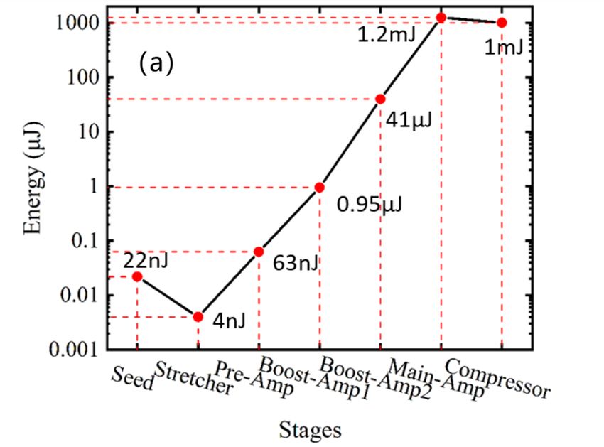
Photonics 2022, 9, 67                                                                                          4 of 8

                        The absorption coefficient was 15 dB/m at 976 nm. Two symmetrical stress bars ensured
                        that the polarization state of the light pulse did not change. The output light from the
                        30/250 amplifier was collimated by lens 1 (L1), and the spatial optical isolator was used
                        to protect the pre-stage device. Then, the direction of the optical path was changed by a
                        dichromatic mirror (DM), and the cladding pump light was further filtered out. The DM
                        used in the experiment was 45◦ high reflection near 1030 nm and high transmittance near
                        976 nm. The spot was then focused into the rod fiber through another lens (L2). In the
                        experiment, the coupling of signal and light had an important effect on the output quality,
                        which not only affected the amplification efficiency, but also affected the beam quality and
                        then affected the compression of the grating pair. In order to match the mode field and
                        NA of the PCF, both L1 and L2 were diffraction-limit aspheric lenses. The focal length and
                        NA of L1 were 30 mm and 0.38, respectively. The spot size after collimation was 1.3 mm.
                        The focal length of L2 was 50 mm, and the numerical aperture NA was 0.20. The focus spot
                        diameter was 57µm, which was smaller than the mode field diameter of the PCF, and the
                        coupling efficiency was higher than 82%. The pump adopted the backward pumping
                        scheme. The pump light was also focused through two sets of lenses, and a DM was added
                        in the middle to separate the amplified signal light for compression. A 110 W, 976 nm
                        LD was used as the pump source. The output tail fiber was multimode fiber with a core
                        diameter of 105 µm and NA of 0.22. The pump light was collimated by two diffractive limit
                        aspheric lenses, L4 and L3, with focal lengths of 12.5 mm and 25 mm, respectively. Pulse
                        synchronous pumping was also used in this stage. The timing sequence of each stage is
                        shown in Figure 2b. The width of the AOM gate was 30 ns to ensure the pickup of a single
                        pulse, and the pump pulse width in each amplifier was 35 µs, 60 µs and 100 µs, respectively.
                        High diffraction efficiency gratings (produced by GitterWerk) were used as the compres-
                        sor, whose diffraction efficiency at 1030 nm was as high as 99.5%. The line density was
                        1739 line/mm, and the size of the gratings were 137 mm × 31 mm and 30 mm × 25 mm,
                        respectively. The parameters of components are summarized in Table 1.

                        Table 1. The parameters of components in the system.

                                   Components                                     Parameter
                                       Seed                                     8.7 MHz, 35 ps, 2 nm
                                       CFBG                                GVD 39.83 ps2, TOD −0.59 ps3
                                   Pre-amplifier                         0.5 m PM-HI-YSF; 1 W, 976 nm LD
                                  Boot-amplifier 1                     1 m PM-10/125-YDF; 25 W, 976 nm LD
                                  Boot-amplifier 2                   1 m PM-30/250-YDF; 5 × 25 W, 976 nm LD
                                  Main-amplifier              Aero GAIN-ROD Module-2.1 by NKT; 110 W, 976 nm LD
                                    Compressor                 1739 line/mm; 137 mm × 31 mm and 30 mm × 25 mm

                        3. Results and Discussion
                             The output energy at all stages is shown in Figure 3a. After the stretcher, the seed
                        pulse energy decreased somewhat. After the four stages of amplification, the energy was
                        amplified to 1.22 mJ measured by the energy meter (OPHIR Nova II). It can be estimated that
                        the B integral of this system was about 8 rad. The B integral was defined as the maximum
                        phase shift [24]. The output energy was 1 mJ after the compressor, the corresponding
                        total compressed efficiency was 82 %. In order to estimate the proportion of ASE in the
                        output energy, we injected 100 µs pulse pump in the main amplifier without signal light.
                        The energy we measured was only 0.3 µJ, far less than 1 mJ. So, the ASE energy can be
                        ignored. The spectral evolution of the system is shown in Figure 3b. The spectral evolution
                        was measured by OSA (YOKOGAWA AQ6370D). The spectral bandwidth of the seed pulse
                        was cut to 21 nm due to the CFBG, and narrowed to 11 nm after subsequent four stage
                        amplification because of gain narrowing effect, and the corresponding Fourier transform
                        limit pulse width was 143 fs. In the experiment, the vertical spacing of the compressor
                        gratings was set as 300 mm, and the incident angle was 63.6◦ . The GVD and TOD provided
                        by the compressor grating pair were −39.75 ps2 and 0.5926 ps3 , respectively. The total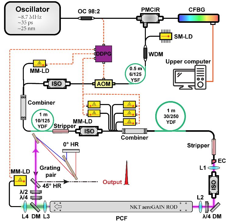
Photonics 2022, 9, x FOR PEER REVIEW                                                                                             5 of 8

Photonics 2022, 9, 67                seed pulse was cut to 21 nm due to the CFBG, and narrowed to 11 nm after subsequent                                5 of 8
                                     four stage amplification because of gain narrowing effect, and the corresponding Fourier
                                     transform limit pulse width was 143 fs. In the experiment, the vertical spacing of the com-
                                     pressor gratings was set as 300 mm, and the incident angle was 63.6°. The GVD and TOD
                                       fiber length
                                     provided    by thein  the system
                                                         compressor       was pair
                                                                      grating   about    28−39.75
                                                                                      were   m, thepscorresponding         introducedThe
                                                                                                       2 and 0.5926 ps3, respectively.    dispersion were
                                       about               2 and 1.23 × 10⁻³ ps3 . In this case, if the total dispersion of the system is
                                     total fiber0.644
                                                 lengthpsin the system was about 28 m, the corresponding introduced dispersion
                                       perfectly
                                     were           matched,
                                            about 0.644   ps2 andthe
                                                                  1.23amount
                                                                        × 10−3 ps3of
                                                                                  . Indispersion     required
                                                                                       this case, if the          by CFBG
                                                                                                          total dispersion  of should
                                                                                                                               the systembe:is 39.11 ps2 and
                                       −0.5938matched,
                                     perfectly        3     the amount
                                                   ps . However,      dueoftodispersion   required
                                                                                the influence     of by
                                                                                                      theCFBG
                                                                                                            SPMshould     be:the
                                                                                                                   effect in  39.11  ps andthe dispersion
                                                                                                                                  system,
                                                                                                                                       2

                                     −0.5938
                                       of CFBGps3. However,    due towas
                                                     at this point     the influence
                                                                            not the of    the SPM
                                                                                        setting   foreffect
                                                                                                        the in  the system,
                                                                                                              optimal        the dispersionThe nonlinear
                                                                                                                         compression.
                                     ofeffect
                                        CFBGof  at this
                                                   the point
                                                        CPA was    not the
                                                              system       setting
                                                                        could    befor  the optimal compression.
                                                                                      compensated                      The nonlinearpositive
                                                                                                         for by an appropriate         effect     dispersion
                                     of the CPA system could be compensated for by an appropriate positive dispersion mis-
                                       mismatch [25]. Therefore, the GVD and TOD of CFBG were appropriately increased to
                                     match [25]. Therefore, the GVD and TOD of CFBG were appropriately increased to
                                       achieve
                                     achieve  thethe    narrowest
                                                    narrowest       compressed
                                                               compressed              pulse width.
                                                                              pulse width.

                                       Figure 3. (a) Evolution of energy at different stages in the laser, (b) evolution of spectrum at different
                                       stages in the laser.

                                            The compression results measured through the autocorrelator (AVESTA AA20DD-30 ps)
                                       are shown in Figure 4. The pulse width fitted by the Gaussian curve was 231 fs, the
                                       time–bandwidth product can be calculated to be about 0.59. The inset is the interference
                                       autocorrelation trace. It can be seen the chirp in the middle region of the pulse was basically
                                       compensated. The sidelobe on both sides was caused by the nonlinear effect accumulated
                                       in the system. By processing the obtained autocorrelation data, its original pulse shape
                                       was obtained. In addition, we integrated the energy over the entire AC window, the peak
                                       power was inferred to be 3.85 GW, and about 90% of the energy was concentrated in the
                                       main peak.
time–bandwidth product can be calculated to be about 0.59. The inset is the interference
autocorrelation trace. It can be seen the chirp in the middle region of the pulse was basi-
cally compensated. The sidelobe on both sides was caused by the nonlinear effect accu-
mulated in the system. By processing the obtained autocorrelation data, its original pulse
shape was obtained. In addition, we integrated the energy over the entire AC window,
Photonics 2022, 9, 67 the peak power was inferred to be 3.85 GW, and about 90% of the energy was concentrated 6 of 8
in the main peak.
Figure 4. The autocorrelation trace of compression pulse, and the inset is the corresponding interfer-
Figure 4. The autocorrelation trace of compression pulse, and the inset is the corresponding inter-
ence autocorrelation
ference trace.
autocorrelation trace.
The polarization extinction ratio of the output light was 25 dB. Because the repetition
rateThe
of polarization extinction
this laser was ratio of
only 1 kHz, andthethe
output light
pulse was 25 dB. Because
synchronous pumping thetechnology
repetition was
rate of this laser was only 1 kHz, and the pulse synchronous pumping technology was
adopted, the system had no obvious heat accumulation, and did not need an additional
adopted, the system had no obvious heat accumulation, and did not need an additional
thermal management control, which not only simplified the whole laser structure, but also
thermal management control, which not only simplified the whole laser structure, but also
improved the stability of the system. The RF curve is shown in Figure 5a. The signal to
improved the stability of the system. The RF curve is shown in Figure 5a. The signal to
noise ratio at 1 kHz was higher than 40 dB. In addition, M2 was measured by 4σ method.
noise ratio at 1 kHz was higher than 40 dB. In addition, M2 was measured by 4σ method.
Photonics 2022, 9, x FOR PEER REVIEW 7 of 8
As shown in Figure 5b, the beam quality of the two axes almost reached the diffraction
As shown in Figure 5b, the beam quality of the two axes almost reached the diffraction
limit with M2 < 1.25. The M2 of seed was about 1.10, and before the main amplifier the
limit with M2 < 1.25. The M2 of seed was about 1.10, and before the main amplifier the
M2 was 1.15. The beam quality maintained high quality transmission in the system.
M2 was 1.15. The beam quality maintained high quality transmission in the system.
Figure 5. (a) The
Figure 5. The radio
radiofrequency
frequencycurve
curveofofthe
thecompressed
compressed pulse,
pulse, (b)(b)
thethe beam
beam quality
quality factor
factor M2 of
M2 of
the pulse
the pulse and the
the spot
spot at
atthe
thefocus.
focus.
4. Conclusions
In conclusion, a high-energy Yb-doped fiber CPA laser has been presented. At a low
repetition rate of 1 kHz, single pulse energy of 1 mJ was achieved by using synchronous
pulse pumping technology, and the output pulse width of 231 fs after compression wasPhotonics 2022, 9, 67 7 of 8
4. Conclusions
In conclusion, a high-energy Yb-doped fiber CPA laser has been presented. At a low
repetition rate of 1 kHz, single pulse energy of 1 mJ was achieved by using synchronous
pulse pumping technology, and the output pulse width of 231 fs after compression was
achieved through the precise matching of the dispersion-adjustable stretcher and the
compressor. The single pulse energy of 1 mJ and the peak power of 3.85 GW with an
output pulse width of 231 fs showed quite excellent performance by the single-channel
fiber CPA systems. In addition, the output beam quality approximated the diffraction limit,
owing to the advantages of PCF. In the future, the average output power can be increased
by increasing the repetition rate, and the energy can be further improved by coherent
beam-combining technology.
Author Contributions: Conceptualization, H.Z.; methodology, H.Z. and J.Z.; software, D.D.; valida-
tion, J.Z., H.X. and J.C.; formal analysis, J.Z..; investigation, D.D.; resources, H.Z.; data curation, J.Z.;
writing—original draft preparation, J.Z.; writing—review and editing, H.Z.; supervision, H.Z.; project
administration, H.Z. All authors have read and agreed to the published version of the manuscript.
Funding: This research was supported by National Natural Science Foundation of China No.61475081
and Department of Science and Technology of Sichuan Province No.2018JZ0015.
Institutional Review Board Statement: Not applicable.
Informed Consent Statement: Not applicable.
Data Availability Statement: Not applicable.
Conflicts of Interest: The authors declare no conflict of interest.
References
1. Nedialkov, N.N.; Imamova, S.E.; Atanasov, P.A. Ablation of metals by ultrashort laser pulses. J. Phys. D Appl. Phys. 2004,
37, 638–643. [CrossRef]
2. Park, C.; Farson, D.F. Precise machining of disk shapes from thick metal substrates by femtosecond laser ablation. Int. J. Adv.
Manuf. Technol. 2016, 83, 2049–2056. [CrossRef]
3. Chung, S.H.; Mazur, E. Surgical applications of femtosecond lasers. J. Biophotonics 2009, 2, 557–572. [CrossRef] [PubMed]
4. Cho, M. Coherent Two-Dimensional Optical Spectroscopy. Chem. Rev. 2008, 108, 1331–1418. [CrossRef] [PubMed]
5. Berera, R.; van Grondelle, R.; Kennis, J.T.M. Ultrafast transient absorption spectroscopy: Principles and application to photosyn-
thetic systems. Photosynth. Res. 2009, 101, 105–118. [CrossRef] [PubMed]
6. Miller, R.J.D. Femtosecond Crystallography with Ultrabright Electrons and X-rays: Capturing Chemistry in Action. Science 2014,
343, 1108–1116. [CrossRef]
7. Mourou, G.; Brocklesby, B.; Tajima, T.; Limpert, J. The future is fibre accelerators. Nat. Photonics 2013, 7, 258–261. [CrossRef]
8. Strickland, D.; Mourou, G. Compression of amplified chirped optical pulses. Opt. Commun. 1985, 56, 219–221. [CrossRef]
9. Stutzki, F.; Jansen, F.; Otto, H.-J.; Jauregui, C.; Limpert, J.; Tünnermann, A. Designing advanced very-large-mode-area fibers for
power scaling of fiber-laser systems. Optica 2014, 1, 233–242. [CrossRef]
10. Hu, Z.Q.; Yang, P.L.; Teng, H.; Zhu, J.F.; Wei, Z.Y. 1-MHz high power femtosecond Yb-doped fiber chirped-pulse amplifier. Int.
Soc. Opt. Photonics 2017, 10619, 106190.
11. Eidam, T.; Hanf, S.; Seise, E.; Andersen, T.V.; Gabler, T.; Wirth, C.; Schreiber, T.; Limpert, J.; Tünnermann, A. Femtosecond fiber
CPA system emitting 830 W average output power. Opt. Lett. 2010, 35, 94–96. [CrossRef] [PubMed]
12. Galvanauskas, A.; Cho, G.C.; Hariharan, A.; Fermann, M.E.; Harter, D. Generation of high-energy femtosecond pulses in
multimode-core Yb-fiber chirped-pulse amplification systems. Opt. Lett. 2001, 26, 935–937. [CrossRef] [PubMed]
13. Galvanauskas, A.; Sartania, Z.; Bischoff, M. Millijoule femtosecond fiber CPA system. In Proceedings of the Advanced Solid-State
Lasers 2001, Seattle, WA, USA, 28 January 2001; Optical Society of America: Washington, DC, USA, 2001; p. 3.
14. Zhao, Z.; Kobayashi, Y. Ytterbium fiber-based, 270 fs, 100 W chirped pulse amplification laser system with 1 MHz repetition rate.
Appl. Phys. Express 2015, 9, 012701. [CrossRef]
15. Röser, F.; Schimpf, D.; Schmidt, O.; Ortaç, B.; Rademaker, K.; Limpert, J.; Tünnermann, A. 90 W average power 100 µJ energy
femtosecond fiber chirped-pulse amplification system. Opt. Lett. 2007, 32, 2230–2232. [CrossRef]
16. Röser, F.; Eidam, T.; Rothhardt, J.; Schmidt, O.; Schimpf, D.N.; Limpert, J.; Tünnermann, A. Millijoule pulse energy high repetition
rate femtosecond fiber chirped-pulse amplification system. Opt. Lett. 2007, 32, 3495–3497. [CrossRef]
17. Eidam, T.; Rothhardt, J.; Stutzki, F.; Jansen, F.; Hädrich, S.; Carstens, H.; Jauregui, C.; Limpert, J.; Tünnermann, A. Fiber
chirped-pulse amplification system emitting 3.8 GW peak power. Opt. Express 2011, 19, 255–260. [CrossRef]Photonics 2022, 9, 67 8 of 8
18. Liu, W.; Schimpf, D.N.; Eidam, T.; Limpert, J.; Tünnermann, A.; Kärtner, F.X.; Chang, G. Pre-chirp managed nonlinear amplification
in fibers delivering pulses. Opt. Lett. 2015, 40, 151–154. [CrossRef]
19. Song, H.; Liu, B.; Li, Y.; Song, Y.; He, H.; Chai, L.; Hu, M.; Wang, C. Practical 24-fs, 1-µJ, 1-MHz Yb-fiber laser amplification system.
Opt. Express 2017, 25, 7559. [CrossRef]
20. Liu, Y.; Li, W.; Luo, D.; Bai, D.; Wang, C.; Zeng, H. Generation of 33 fs 93.5 W average power pulses from a third-order dispersion
managed self-similar fiber amplifier. Opt. Express 2016, 24, 10939–10945. [CrossRef]
21. Lü, R.; Teng, H.; Zhu, J.; Yu, Y.; Liu, W.; Chang, G.; Wei, Z. High power Yb-fiber laser amplifier based on nonlinear chirped-pulse
amplification at a repetition rate of 1 MHz. Chin. Opt. Lett. 2021, 19, 091401. [CrossRef]
22. Deng, D.; Zhang, H.; Gong, Q.; He, L.; Li, D.; Gong, M. Energy scalability of the dissipative soliton in an all-normal-dispersion
fiber laser with nonlinear amplifying loop mirror. Opt. Laser Technol. 2020, 125, 106010. [CrossRef]
23. He, L.; Zhang, H.; Deng, D.; Gong, Q.; Zu, J.; Meng, K. Effect of Phase Relations on Speckle Pattern: Simulation and Measurement.
IEEE Photonics J. 2019, 11, 7102008. [CrossRef]
24. Agrawal, G. Nonlinear Fiber Optics, 4th ed.; Academic Press: London, UK, 2006.
25. Schimpf, D.; Seise, E.; Limpert, J.; Tünnermann, A. Self-phase modulation compensated by positive dispersion in chirped-pulse
systems. Opt. Express 2009, 17, 4997. [CrossRef] [PubMed]You can also read