ZalaZONE PROVING GROUND - Zsolt SZALAY Ph.D. Head of Research&Innovation - Title - UNECE
←
→
Page content transcription
If your browser does not render page correctly, please read the page content below

Title
 Sub-title

ZalaZONE PROVING GROUND
Zsolt SZALAY Ph.D.
Head of Research&Innovation

  1                           Chapter

Disruptive changes
    Technology change in the automotive industry
    •   AD vehicles are no longer separate entities
    •   Human driver is getting out of the control loop
    •   New algorithms (e.g. machine learning) current validation will not

    „Conventional” vs AD vehicle testing and validation
    •   Vehicle dynamics testing in itself is not enough
    •   Testing vehicle environment perception capabilities
    •   Testing vehicle interaction to other vehicles and the infrastructure
    •   Connected vehicles require testing of communication technologies

        Conclusion: new testing and validation methods thus
             dedicated proving grounds are necessary

2       Disruptive changes
Decision on strategic R&D investment
Unique test facility
 Capacity constraints in Europe in area of vehicle dynamic testing
 Technology change in vehicle industry – single vehicle vs. co-operative vehicle control:
 different development environment is required
 Decision of Hungarian Government in 2016: „contribution to the European automotive
 community”
       Test field for classic and automated and connected vehicles in Hungary

                                                              1000 km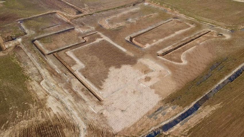
Co-operating industrial partners in requirement definition
Industry demand is fulfilled
Automotive Working Group, 2015:
AImotive, AVL, BME GJT, BOSCH, Commsignia, Knorr-Bremse,
Continental, EVOPRO, NKH, NI, SZTAKI, ThyssenKrupp Presta, TÜV
Rheinland, ZF
    • Detailed technical specification of the classic elements of vehicle
      dynamics and physical structure of the automated vehicle tests
    • Draft specification of the autonomous environment and related
      communication infrastructure
    • Technical proposal for autonomous vehicle public road testing

ICT Working Group, 2017:
BME HIT, BME KJIT, BPC, Ericsson, HUAWEI, Kapsch, Magyar Közút,
Magyar Telekom, NFM, NMHH, Nokia, Oracle, RWE, Siemens, SWARCO,
T-Systems, Vodafone (compared to the new members of the automotive
working group)
    • Detailed specification of the autonomous vehicle environment and
      related communication infrastructure
        Status of the project                                               4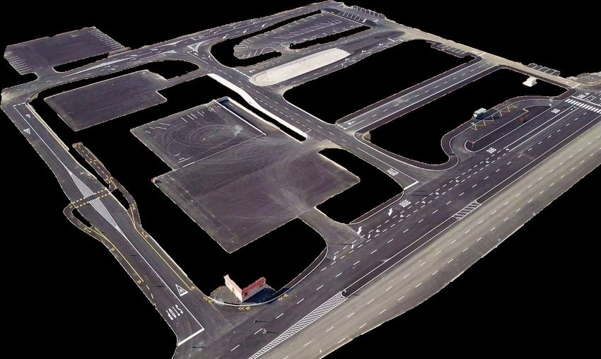
Layout of the Proving Ground
Traditional and CAV testing modules
 Area: 265 ha
 Budget: 140 million EUR
 Standard vehicle dynamics testing and validation
 Fully integrated autonomous vehicle testing and
 validation
 Environment preparation (obstacles,
 traffic signs, traffic control, other
 vehicles, vulnerable road users, etc.)
 Complex driving and traffic situations
 Smart City features
 From prototype testing till series production
 testing and validation
 • Not only automotive but telecom
     and IT test environment
 • Not only road traffic but drone traffic,
     recovery and counter drone activities
 • 8+1 Unique Testing Propositions                  Source: Szalay et al, PerPol TraspEng 2017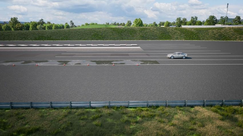
Business & Operation Model
Operation models will change
                         Vehicle partners
                          (OE, Tier1, …)
                                          Communication partner

                                                                System partner

                                            Testing ZONE

                        Simulation            Data collection
  Modules (with                                                     Data management       Engineering
                     (scenarios, cases,        (operation of
 classic services)                                                 (operation of cloud)    Services
                       disturbances)         sensory system)

                                            SERVICE CONTENT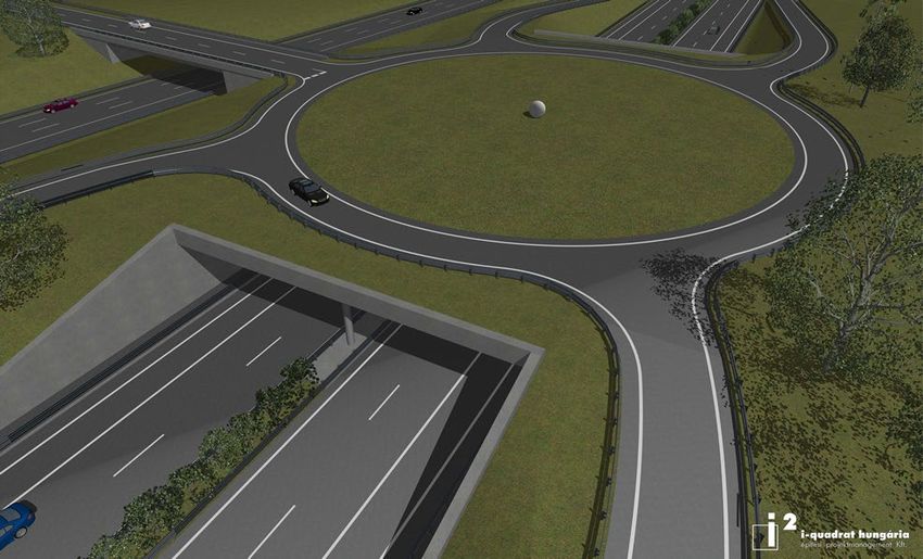
PROJECT DEVELOPMENT
Phases of the project
Phase 1: 2018 Phase 2.a: 2019 Phase 2.b: 2020
Dynamic platform Dynamic platform Dynamic platform
Braking surfaces Smart City basic road grid Smart City basic road grid
Handling course – high speed Braking surfaces Braking surfaces
Smart City basic road grid I Handling course – high speed Handling course – high speed
Main entrance building Rural road – Eastern section Rural road – Eastern section
Technical building Smart City road grid II, facades, buildings Smart City facades, buildings
(Innovation center – by industrial park) Highway section Highway section
Rural road – Eastern section Rural road – Southern section
Main entrance building Handling course – low speed
Technical building Smart City technology+
Control center Further dynamic modules
High-speed oval
Main entrance building
Technical building
Control center
Research center
Proving Ground benchmarks

    Mcity   Aldenhoven   Boxberg
                                                                             AstaZero
                                   ZalaZONE            Millbrook

                                              Idiada                      Horiba-Mira

               Nardó                                          Papenburg

9      Proving Ground benchmarks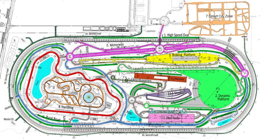
Automotive Proving Ground ZalaZONE

10   Automotive Proving Ground ZalaZONE
Construction of Complex Test Scenarios
SMART City Zone – Buildings

11   Details of the modules
Proving Ground Modules
SMART City Zone – Separated Function Zones

             ready actually (Dec/2018)

                                                     1.   Low-speed,
                                                          parking area

   1
                                                     2.   Multi-lane high

                                 3
                                                          speed area

                                                     3.   Downtown area

                          2                  4       4.   Suburban area

                                                     5.   T-junction area

                                                 5
Proving Ground modules
Dynamic platform
Physical parameters:
• 300m diameter asphalt surface
• Acceleration lane 760m and 400m long
• 20m wide FIA emergency area
• Watered surface (optional)
• Watered basalt surface at eas acceleration lane (phase 2.)
• 1% inclination to south
• Separated return way
Autonomous vehicle test cases:
• Platooning at free trajectory
• Cooperative vehicle control at high and medium mue with
different trajectories (double lane change, J-turn etc.) at
stability limit (ABS, ESP activity)
• Fix position obstacle (dummy car or pedestrian)
• Euro NCAP scenarios
13 Details of the modulesProving Ground modules
Braking platform
Physical parameters:
• 8 different surfaces:
• Chess surface: asphalt/tiles
• Asphalt mue=~1 (optional watering)
• Tiles mue=~0.1 (wet)
• Blue basalt mue=~0.3 (wet)
• Asphalt mue=~0.8 (optional watering)
• Treated concrete mue=~0.6 (wet)
• Asphalt mue=~0.8 (reserve surface)
• Aquaplaning basin (max. 5cm wet depth)
• 200m surface length
• 750m acceleration lane
• 20m safety area at both side, 150m at the end
Project Phase 1 2017-2018
Autonomous vehicle test cases:
• Platooning at physical limits; drive through or braking at
various surfaces up to high speed
• Cooperative vehicle control at physical limit, moving or static
obstacle, at various speeds during ABS, ATC, ESP activity
14 Details of the modulesProving Ground modules
Handling course
Physical parameters:
• Low (60km/h) and high speed (120km/h)
section
• 1.300m and 2000m length
• width: 6 and 12m
• 20m wide gravel covered safety zones
• Various topography
• V2X coverage for communication tests at
various terrain
Autonomous vehicle test cases:
• Platooning at medium speeds at diverse
topography
• Cooperative vehicle control at diverse
topography and limited visibility
15 Details of the modulesProving Ground modules Rural road Physical parameters: • 500m 2x2 lane motorway • 2500m 2x1 lane rural road • Partly watered surface • 5G test network • V2X communication coverage • GPS base station • Public road like layout (junctions, road surface, geometry) Autonomous vehicle test cases: • Platooning on rural road at realistic conditions, various type of junctions, roundabouts • Diverse lane layout: 2x1, 2x2, 2+1, • Diverse topography • Moving and static obstacles • Construction site situation • Various road side elements: trees, fences, grass etc. 16 Details of the modules
Proving Ground modules
Motorway
     Parameters:
     • 1500m 2 x 2+1 lane motorway
     • 100m real tunnel
     • Partly watered surface
     • VMS, 5G test network
     • V2X communication coverage
     • GPS base station
     • Public road like layout (junctions, road
        surface, geometry)

     Autonomous vehicle test cases:
     • Platooning on motorway at realistic        Project Phase 1 2017-2018
        conditions, exits and entrances
     • Platooning and cooperative control with
        limited communication (tunnel)
     • Moving and static obstacles
     • Construction site situation
     • Multi level junction

17      Details of the modules
Proving Ground modules
High-speed oval
Parameters:
4.400m length
• 900m straight sections
• 350m curve radius
• 200km/h neutral speed at curves
• max. 250km/h at straights
• 1% inclination to south
• 4 lanes
Autonomous vehicle test cases:
• Platooning at high speed motorway situations
• Cooperative vehicle control at high speed
• Fix position and moving obstacles (dummy car or
pedestrian)
• V2I, V2V communication tests at high vehicle speed
18 Details of the modulesProving Ground modules
Communication network
• 3 level approach:
• 1st level: ITS G5 basic V2X test
environment
• 2nd level: V2X developer
environment: freely configurable,
open interface for application
developers, full data logging
infrastructure
• 3rd level: fully customer defined
test environment
• 5G cellular test network for future ITS
applications
• Redundant layout for parallel customer
networks
19 Details of the modulesEducation, Research&Innovation
RECAR Program
•    REsearch Center for Autonomous Road vehicles (RECAR)

•    Market Demand
      •   Global trends and timing in automotive development
      •   4 OEMs and 15 TIER1s are in Hungary
      •   Continuous need for qualified engineers

•    Education and R&D initiatives - multidisciplinary cooperation
      •   Academic sphere (BME, ELTE, MTA SZTAKI)
           •  BME VIK, KJK, ÉPK, GPK
      •   Industrial partners (Bosch, Knorr-Bremse, Continental)

•    RECAR Education Program
      •   Autonomous Vehicle Control Engineer MSc in English
      •   Computer Science for Autonomous Systems MSc in English
      •   Vehicle Test Engineer BProf in Hungarian

21    RECAR Program
Autonomous Vehicle Control Engineer MSc 22 Autonomous Vehicle Control Engineer MSc
RECAR research program

23   RECAR research program
Multi-level testing environment
From computer to real traffic

                     PUBLIC ROAD             REAL TRAFFIC SYSTEM TESTS

         LIMITED PUBLIC ROAD                       ALMOST REAL ENVIRONMENT TEST

        PROVING GROUND                                  CONTROLLED SYSTEM TEST

                                                             TECHNOLOGY, COMPONENT, SYSTEM
        LABORATORY                                           INTEGRATION AND VEHICLE-IN-THE-
                                                             LOOP TESTS

                                                                           PROOF-OF-CONCEPT,
     SIMULATION                                                               FEASIBILITY AND
                                                                                  DURABILITY
                                                              Source: Szalay, VSDIA 2016

              Autonomous Vehicle Testing & Validation Pyramid
Scenario-in-the-Loop concept
Digitalized test environment
The entire proving ground in its reality
must be provided in the virtual simulation
Digitalized test environment in which the positions and
environment pathways of lanes are known and exactly
correspondents to the real testing area.
HD map
To create this, the most effective way is surveying the track using laser scanning technology and generate a high
definition 3D point cloud [9]. The results of the surveying should be readable for most simulation software, and
therefore the “point cloud” must be converted into widely used industrial standards such as OpenDriveTM or
OpenCRGTM or other open source file formats.
25Scenario-in-the-Loop concept
The tested vehicle and its localization
The investigation of the Vehicle Under Test (VUT) or ego vehicle is the main
Vehicle Under Test target of the test scenario.
The VUT can be split in two groups depending on its SAE automation level.
If the ego vehicle falls below automation Level2 then the maneuver should be
performed for good reproducibility by a driverless test system (DTS)
Above automation Level2 the tested ego vehicle has a certain self-driving capability
and able to drive from location A to location B within the proving ground.
Localization The VUT has to be registered with high precision by the traffic simulation as
an active road user, which requires at least 2 cm accuracy in positioning.
Currently by mounting an inertial measurement unit (IMU) linked with a
differential GNSS to the real car, its position on the test track can be located
with the desired accuracy. The combination of the IMU and DGNSS are
commonly referred to as inertial satellite sensors (INS).
27Scenario-in-the-Loop concept
Disturbances Disturbances
The outputs of SciL processes are the potential disturbances,
ergo every element which can affect the VUT’s behavior.
There are five main type of disturbances:
• VUT Sensor spoofing
• V2X communication spoofing
• Infrastructure elements
• Moveable targets
• Full-control real vehicles
The disturbances can be categorized by three aspects:
• Real or virtual objects
Real object can be perceived by the VUT own sensors, but
virtual objects required sensor and communication spoofing
• Controlled by wire or wireless
The communication between the disturbances and the control software can be carried
out by wireless communication or directly by wire.
• Closed or open loop control
The real-time acquiring of the actual status and position of the movable objects are also
necessary for the continuous control of the defined scenario.
28Scenario-in-the-Loop concept
Architecture (operating principle) Direct connection
Wireless connection
Simulation &
Digitalized test Control Software
environment
running offboard
Localization
HD map Scene Objects
Vehicle Under Test
Scenario
realized by the VUT & Scene Objects
29Layer 4 - Limited Public Road Tests
• Dedicated Test Routes
• 5G Demo Network
• ITS G5 Coverage
• Smart City and
Connected Car features
30 Layer 4 - Limited Public Road TestsLayer 5 - Public Road Testing
Today…
Public road tests are allowed in Hungary since 12th of April
11/2017. (IV.12.) NFM decree (5/1990, 6/1990 KöHÉM)
Anywhere in Hungary for automotive R&D companies
… and tomorrow
Specific routes on public road with
enhanced services for CAV tests
Integration to Proving Ground in
Zalaegerszeg
Smart city zone in Zalaegerszeg
Part of cross-border cooperation
between Zalaegerszeg-Graz-Maribor
• 2018 Q2: M7 highway
• 2019: M70
• 2020: Zalaegerszeg smart city
• 2021-2022: R76 highway
31 Layer 5 - Public Road TestingZalaZONE Construction Status
ZALAZONE - Region Zala

                         34
You can also read