1.0 INTRODUCTION Cadastral shoreline digitization project: Waikato Region
←
→
Page content transcription
If your browser does not render page correctly, please read the page content below
2019-06 LRep
Status: Open
16 July, 2019

Prepared for:
Waikato Regional Council

Cadastral shoreline digitization project: Waikato Region

1.0 INTRODUCTION
When large-scale European settlement began in the 1840s, Crown and New Zealand Company
surveyors began mapping harbours, towns, roads, arable land, geology, and occupation and
ownership boundaries. Plans containing legal boundaries were referred to as cadastral plans;
however, the term is now loosely used to cover all types of surveyed historical maps. Within
these cadastral plans can be found quantitative information of coastal landforms that predate by
some 60 to 100 years the vertical aerial photographic record of such features which began, for
most of the New Zealand, in the 1940s. One of the earliest (1842) settlement plan for is shown in
Figure 1 with modern shoreline overlain to illustrate dramatic coastal change through historical
time at this location However, as yet we have been unable to locate information as to how this
map was surveyed. While this limits its know accuracy and quantitative usefulness for
comparative analysis, it does, nonetheless provides invaluable qualitative geomorphological
information.

In 1874, the government reviewed the country’s surveying and mapping and found only about
30% of the land had been adequately triangulated and only around 7% had accurate cadastral
boundaries. In 1876, with the abolition of the provincial government system, the Department of
the Surveyor-General was created. This department merged with the Crown Lands Department
in 1891 to become the Department of Lands and Survey which persisted until the government
reforms of the 1980. The Department of Lands and Survey then became the Department of
Survey and Land Information (DOSLI) and in 1996 DOSLI was split into Land Information New
Zealand (LINZ) and Terralink NZ Ltd.

Surveyors often recorded or sketched topographic features in their field books and their
cartographers sometimes reproduced these on their plans. The coast itself was defined using a
range of indicators such as the land-sea boundary, the high water mark (HWM) at the time of
survey, the dune line, the cliff line, or a river, stream or estuary bank. Inclusion of early cadastral-
based coastline information in temporal landform analysis can potentially provide greater insight
into the nature and rates of past change and hence lead to more reliable prediction of future
change.

However, abstracting usable data from these plans is not straightforward due to inaccuracies
incurred during the original survey and plan production, storage conditions and the mediums
aging characteristics, digital transformation procedures by LINZ in the 1980s and 1990s, and
shoreline digitization processes used in the present project. In addition, there are issues relating

  COASTAL SYSTEMS LIMITED. Coastal Management, Hazard Assessment, Research and Education Consultancy.
70 Karaka Street. Castlecliff Beach 4501, South Taranaki, New Zealand. Phone: 64 634 44214, Mobile: 021 057 4189,
                     Email: enquiry@coastalsystems.co.nz : Web Site: www.coastalsystems.co.nz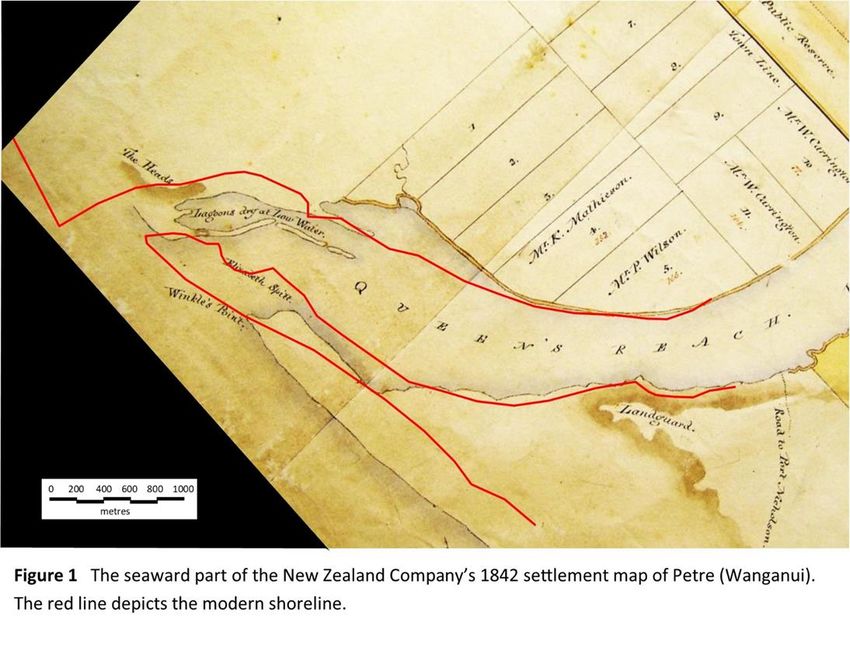
2

to the nature and measurement of the landform indicators themselves. Accuracy and error
assessment are thus major considerations when using cadastral-based data and this will be
discussed in the following section (2) on Plan Characteristics and Accuracy.

The present project's objective is to provide digitized shorelines from all1 historical survey plans
from the Waikato Regional Council’s jurisdiction. Plan and shoreline detail and output accuracy
are summarised in the Metadata section (3). This procedure covers the following areas:

-Buffalo Beach

-Cooks Beach

-Kaiaua

-Marakopa

-Miranda

-Pauanui

-Port Waikato

-Raglan

-Tairua

Project outputs are provided in a folder for each site that contains the following:

-A spreadsheet (named "metadata") with an introductory section (sheet), a survey plan
characteristics and accuracy section (sheet) and, a sheet with details for each location;

-The set of digitized shorelines for each site

-The corresponding set of survey plans that the shorelines were abstracted from - these plans are
included to assist a user with shoreline interpretation.

1. Included are survey plans available in the LINZ data-base and any additional plans that are easily
accessible. However, only plans containing shorelines actually surveyed for the production of that plan
were processed, i.e. plans reproducing shorelines from earlier plans (a common practice) are not included.
If uncertainty surround the dating authenticity of a shoreline, this is noted in the Metadata.

  COASTAL SYSTEMS LIMITED. Coastal Management, Hazard Assessment, Research and Education Consultancy.
70 Karaka Street. Castlecliff Beach 4501, South Taranaki, New Zealand. Phone: 64 634 44214, Mobile: 021 057 4189,
                     Email: enquiry@coastalsystems.co.nz : Web Site: www.coastalsystems.co.nz
3

  COASTAL SYSTEMS LIMITED. Coastal Management, Hazard Assessment, Research and Education Consultancy.
70 Karaka Street. Castlecliff Beach 4501, South Taranaki, New Zealand. Phone: 64 634 44214, Mobile: 021 057 4189,
                     Email: enquiry@coastalsystems.co.nz : Web Site: www.coastalsystems.co.nz
4
2. PLAN CHARACTERISTICS and ACCURACY
2.1 Types of survey plan
There are three main types of cadastral survey plan:
- Survey Office Plans (SO)
- Māori Land Plans (ML)
- Deposited Plans (DP)
As well as the identification prefix, each plan has a number which is broadly chronological within
each type.
Cadastral title plans can date back to the 1840s and the older plans may include names of
European settlers, Māori and early English place names, as well as the ‘appellation’ (legal
description).
2.2 Searching for cadastral plans
About 95% of historical plans were scanned during the 1990s and are held by LINZ. The
remainder are roll plans or very fragile plans and Archives NZ will copy these upon request.
However, identifying historical plans containing shoreline information for an area of interest is
not straightforward as the LINZ index simply gives plan names but no date, no actual area of
coverage nor any reference to a shoreline. Locating relevant plans can thus be particularly time
consuming and expensive as LINZ charge per plan or for a search licence.
2.3 Shoreline indicator
As noted in the Introductory section, the surveyed shoreline may be indicated by several
different features and these are given in the relevant metadata. For open coast beaches the high
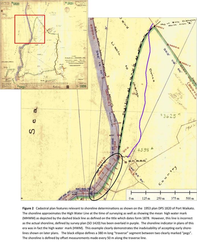
water mark (HWM) at the time of survey was typically used (e.g. see Figure 2). This indicator
would later be replaced by the mean high water mark (MHWM), apparently this being defined by
observation over time (for example 2 months in the case of 1913, DP 9251), although it appears
surveyors may have used the terms interchangeably (e.g. see Figure 2 caption). Actual elevation-
based MHWM were eventually adopted from the 70s using various MSL datum. In some cases
the foredune toe or vegetation-front were used as open coast shoreline indicators. If no indicator
was marked on beach plans, then the HWM is assumed. Cliff indicators (clifftop of cliff base,
HWM and even a fronting-platform edge) were invariably not marked on plans; the field book
may assist interpretation as may comparing the georeferenced plan with aerial photography. A
range of Inlet indicators may also have been used including HWM, edge of bank or channel
margin at the time of surveying.
It is important to know the nature of the indicator as some can vary daily in response to marine
or fluvial conditions, while others such as a foredune toe or vegetation line respond only to
extreme storm events (erode) and then recover (prograde) over months to years. Inlets are the
most dynamic of coastal landforms with their margins able to migrate alongshore 10s or even
100s of metres per year making the indicator uncertainty less significant in determining historical
behaviour (variation/extremes). Cliff lines are the most stable indicators with erosion (cliffs
COASTAL SYSTEMS LIMITED. Coastal Management, Hazard Assessment, Research and Education Consultancy.
70 Karaka Street. Castlecliff Beach 4501, South Taranaki, New Zealand. Phone: 64 634 44214, Mobile: 021 057 4189,
Email: enquiry@coastalsystems.co.nz : Web Site: www.coastalsystems.co.nz5
don't prograde) being dependent on the rate of marine undercut and terrestrial weathering and
can range from virtually nothing for hard rock to over metres per year for weakly lithified
material.
The relationship between a cadastral plan shoreline and the shoreline derived from the later
vertical aerial photography, satellite imagery or LIDAR is also critical as the associated data sets
may not be compatible and some allowance must made if such data sets are to be combined for
analysis. For example, the vegetation front is typically used as the shoreline indicator with aerial
photographs and satellite images and this indicator is located landward of the HWM and MHWM
hence introducing a systematic error. Some reconciliation can me made if the typical variation
between indicators (e.g. vegetation front and MHWM) can be determined from modern
monitoring data - and it is reasonable to assume temporal consistency. Alternatively, if
numerous aerial samples are available and the HMW is definable on them, then a uniform data
set can be generated that includes the cadastral data. However, in this case, short-term
variability (as noted above) can obscure a longer-term signal making the identification of
statistically significant relationships less likely. By contrast, the cliff-top can be detected in aerial
and satellite images thereby enabling a consistent data-set free of short-term noise to be
generated and thus provide for significant trend definition. LIDAR provides three-dimensional
data so can merge with the elevation-based indicators used in the later cadastral plans.
2.4 Shoreline measurement
Surveys were typically carried out using a "traverse" which consists of a series of adjoining
straight lines forming a closed outline with each segment being defined by a bearing and length.
The traverse could thus be accurately plotted and was also tied in to a standard co-ordinate
system via observable Trig Stations. Natural features such as the shoreline were then located by
making "offset" measurements at right angles to the traverse line which was ideally located close
to, and parallel with, the shoreline of interest (examples marked in Figure 2). Later the elevation-
based MHWMs were defined by locating the relevant elevation on the beach face then "fixing"
this position using distance and bearing measurements. Alongshore spacing of adjacent shoreline
measurements varies between about 20 m and 500 m depending on shoreline variation and the
purpose (hence accuracy requirements) of the survey.
Plans depicting a shoreline but no traverse line, and/or offsets or fixings, are problematic in that
the shoreline may have been copied from another (earlier) plan, or the shoreline location may
have simply been estimated/sketched. Every effort was made to locate plans of an original
survey. Such information, or lack of, is noted in the metadata.
Surveyors recorded their observations in a uniquely numbered “Field Book” and most books from
the 20th century and also some from the 19th century are available from the LINZ archive. The
Field Book may include sketches and additional interpretive information not shown on the plan.
2.5 Accuracy
The various limitations described above relate to the detection/measurement accuracy and
stability of reference shorelines and the compatibility of shorelines derived from different
sources. These limitations can be assessed based on the information summarised in the
metadata coupled with the requirements of a contemporary use.
COASTAL SYSTEMS LIMITED. Coastal Management, Hazard Assessment, Research and Education Consultancy.
70 Karaka Street. Castlecliff Beach 4501, South Taranaki, New Zealand. Phone: 64 634 44214, Mobile: 021 057 4189,
Email: enquiry@coastalsystems.co.nz : Web Site: www.coastalsystems.co.nz6
By contrast, the accuracy of the digitized cadastral shoreline in relation to the original ground
survey can be numerically defined by combining the following three components:
2.5.1 Graphical errors
These include original survey and plotting errors, sheet dimensional distortions, general sheet
deterioration and scanning, co-ordinate conversions and other errors incurred when LINZ
compiled their (digital) data base. However, the major factor affecting graphical errors is the
scale at which the original plan was drawn. The accuracy of the LINZ spatial data-base has been
calculated (95% confidence level by LINZ) in relation to scale and relevant values are given in the
metadata. Note that the scale was missing on some early plans so for the present exercise it was
estimated based on the overall surveyed distance depicted in a plan. If the grid-based
georeferencing approach is used (see below) then this error will reduce somewhat; however for
the present exercise no adjustment has been made.
2.5.2 Georeferencing errors
These occur when transforming a plan to a predetermined scale, orientation and co-ordinate
system to enable the overlaying of images for comparative analysis. Such a transformation
involves the use of corresponding ground control points (typically boundary pegs or
intersections) evident in both the LINZ spatial data base (the source information) and on the plan
being georeferenced. Note, while the LINZ data-base depicts boundaries and other
features/attributes, the actual plan LINZ adopted them from is not referenced and has to be
"discovered".
It should be noted that plans made using the geodetic co-ordinate system (includes earth
curvature) which were produced from 1950s, can be georeferenced using the map's northing and
easting grid (grid-based approach) which is converted to NZTM (or whatever system is used for
the georeferencing project) using the LINZ online LINZ co-ordinate conversion program.
Georeferencing can distort the original image to best fit the set of ground control points. An
upper value (95%) is determined from the fitting errors to represent the georeferencing error and
this is recorded in the metadata. The drafting and distortional accuracy of the plan to be
transformed tends to determine the number of ground control points used in the transformation,
with a greater number being required the more inaccurate the plan. The number of control
points is also listed in the metadata. Where the plan is of particularly poor quality it is
georeferenced in parts which are then merged to achieve acceptable accuracy.
Earlier plans may not show boundaries corresponding to those in the LINZ data base and in such
cases more recent survey plans (which include earlier boundaries) are georeferenced and then
used as the source image/data to georeferenced an earlier plan - a process referred to as
"georeferencing step-back". Alternatively, processing more modern plans may help identify
discrete pieces of LINZ data that are included but not obviously identifiable on an early plan - a
process referred to as "georeferencing interpretation". Any plans used for step back or
interpretation in additional to those used for shoreline digitizing, are also listed in the Metadata.
The georeferencing error term was increased using the RSS approach (see equation 1 below)
where step backing is used.
It is also noted that where a cadastral shoreline is only available on a plan “compiled” from other
plans, an additional georeferencing component (using the RSS approach) was also included in the
error analysis.
COASTAL SYSTEMS LIMITED. Coastal Management, Hazard Assessment, Research and Education Consultancy.
70 Karaka Street. Castlecliff Beach 4501, South Taranaki, New Zealand. Phone: 64 634 44214, Mobile: 021 057 4189,
Email: enquiry@coastalsystems.co.nz : Web Site: www.coastalsystems.co.nz7
In some situations LINZ-based georeferencing points were simply not available and such a plan
could not be utilized. However, in some cases stable geomorphological features could be
identified based on aerial photo comparison. For example, where the edge of a well-defined rock
outcrop showed minimal change between the first and last available aerial images (1940s to the
present), it is reasonable to assume there was similarly minimal change back to when the feature
was located during the cadastral survey – thus enabling it to be used as a ground control point.
Finally, where only 2 control points were available, the plan of interest was physically scaled and
rotated (using a drawing programme) to fit the source plan. This analogue approach was that
used exclusively before analytical transformation was available.
2.5.3 Digitization errors
Manually digitizing a georeferenced shoreline introduces a third source of error which can
become significant if the original plan was in poor condition (distorted or disintegrating). The
variation is sampled and an upper value selected for inclusion in the metadata and combined
error computation.
The combined error is calculated using the root sum of squares (RSS) procedure (equation 1)
derived from variance addition as these error terms are considered to be independent of each
other.
(1)
Where CE = combined error, E1 = first error term, and En = nth error term.
In addition, where multiple georeferencing error terms are involved, e.g. where "step backs"
have been used, then these are first combined using the RSS method. The combined error for
each plan is listed in the metadata.
As noted earlier, an upper value is used for each error term (as defined by ~95% Confidence
Interval) and equation 1 produces a corresponding upper value. This approach is used as coastal
hazard assessments require the derivation of very likely impact. By contrast, the likely error
range would be less than half this value.
Comments are also included in the metadata which note abnormalities associated with a
particular plan and/or its georeferencing transformation. Of particular note is where a plan has
plotted an earlier shoreline. These are often found to be in error when the early plan itself is
georeferenced. Errors were typically 5 to 30 m; however, in the most extreme case, miss-plotting
can exceed 150 m (see Figure 2 and comments made in the Port Waikato metadata). We
emphasise the need to locate and process original survey plans rather than use earlier shorelines
drawn on later plans.
COASTAL SYSTEMS LIMITED. Coastal Management, Hazard Assessment, Research and Education Consultancy.
70 Karaka Street. Castlecliff Beach 4501, South Taranaki, New Zealand. Phone: 64 634 44214, Mobile: 021 057 4189,
Email: enquiry@coastalsystems.co.nz : Web Site: www.coastalsystems.co.nz8
COASTAL SYSTEMS LIMITED. Coastal Management, Hazard Assessment, Research and Education Consultancy.
70 Karaka Street. Castlecliff Beach 4501, South Taranaki, New Zealand. Phone: 64 634 44214, Mobile: 021 057 4189,
Email: enquiry@coastalsystems.co.nz : Web Site: www.coastalsystems.co.nz3. META DATA
3.1 Buffalo Beach
Year Plan Name Shoreline Shoreline Shoreline definition: Georeferencing Scale ## Plan errors Georeferencing Shoreline Combined Comments
Traverse * Type ^ Offsets (spacing) # control (Chains to inch) (LINZ) error digitiz error error (95%)
BUFFALO BEACH
Plans for shoreline digitzation
1870 ML 1973 Yes HWM assumed No 7 1: 7920 (10) 9.2 8.9 3.6 13.3 6 LINZ, 1 geomorph, inaccurately drawn. Georeferenced the area of interest only
1876 ML 4047 Yes HWM assumed No 3 1:792 (1) 0.9 3 1.5 3.5 scaled and rotated to morphologically shape-fit DP 3430
1879 DP 3430 Yes Various ^ No 3 1: 3960 (5) 5.5 3.7 1 6.7 ^ HWM assumed on coast. Both reclaimed shoreline plus assumed bank within inlet
Georefn as 2 parts. 3 points each. One stepback control point off 1885 SO 3919
1882 DP 95 Yes Bank assumed No# 3 1:1188 (1.5) ## 1.3 0.7 0.3 1.5 # transect along/close to bank. ## estimated
1883 DP 357 Partial HWM assumed Few (200-400m) 8 1: 6336 (8) ## 7.9 4.1 1.5 9.0 ## estimated
1885 DP 379 Yes Bank and wall ^ Yes (15 to 20 m) 3 1:1188 (1.5) 1.3 0.3 0.3 1.4 ^ Two shorelines named: edge of bank and breakwater (of Kaui slabs)
1890 DP 921 Yes Bank assumed No # 4 1:3168 (4) ## 4.4 1.2 0.7 4.6 # transect along bank. ## estimated
1896 ML 3550 Yes HWM assumed No 5 1: 7920 (10) 9.2 2.4 2 9.7 stepback georeference of 1913 ML 9050
1906 DP 5145 Yes HWM assumed No 4 1: 7920 (10) 9.2 5 2 10.7
1911 SO 16673 No HWM assumed No 7 1: 7920 (10) 9.2 6.9 2 11.7 HIGH UNCERTAINTY - a roading plan with compiled shorelines - possible sketching
1913 ML 9050 Yes * HWM assumed No 6 1: 3168 (4) 4.1 1.8 0.7 4.5 * seaward road traverse along shoreline
1927 DP 21167 Yes MHWM Yes (50 to 80 m) 8 1: 6336 (8) ## 7.9 3.3 1.5 8.7 one control point scaled
1929 DP 22686 Yes MHWM Yes (20 to 60 m)# 5 1: 1584 (2) 1.8 1.4 0.5 2.3 Incorporated offsets within harbour from plan 1926 SO 24196
1954 DPS 3542 Yes MHWM Yes (40 to 100 m) 6 1: 1584 (2) 1.8 0.7 0.5 2.0
1955 DPS 4704 Yes MHWM Yes (20 m) 7 1: 3168 (4) 4.1 2.8 0.7 5.0 stepback georeference of 1953 DPS 2792
1956 DPS 4410 Yes MHWM Yes (45 m) 3 1: 1584 (2) 1.8 0.8 0.5 2.0
1969 SO 45056 Yes MHWM Yes (20 m) 4 1:792 (1) 0.9 0.6 0.2 1.1
Email: enquiry@coastalsystems.co.nz : Web Site: www.coastalsystems.co.nz
Reference Plans (for "stepback" georeferencing and/or interpreting LINZ data)
1885 SO 3919 3
1926 SO 24196 4
1930 DP 23068 5
1953 DPS 4725 5
1953 DPS 2792 4
1954 DPS 3542 6
COASTAL SYSTEMS LIMITED. Coastal Management, Hazard Assessment, Research and Education Consultancy.
1955 DPS 4704 5
70 Karaka Street. Castlecliff Beach 4501, South Taranaki, New Zealand. Phone: 64 634 44214, Mobile: 021 057 4189,
9
1957 DPS 4410 43.2 Cooks Beach
Year Plan Name Shoreline Shoreline Shoreline definition: Georeferencing Scale ## Plan errors Georeferencing Shoreline Combined Comments
Traverse * Type ^ Offsets (spacing) # control (Chains to inch) (LINZ) error digitiz error error (95%)
COOKS BEACH
Plans for shoreline digitzation
1862 ML 15834 No* HWM assumed No 2 1: 7920 (10) 9.2 20 7 23.1 HIGH UNCERTAINTY as may incorporte sketching. See box for further details
1890 SO 5500 Yes HWM assumed No 5 1: 7920 (10) 9.2 6 2 11.2
1920 SO 21048 Yes HWM No 3 1: 3960 (5) 5.5 4.2 1 7.0
Notes 1862 plan ML 15834 was the only Cooks Beach survey plan available until the subdivisions of the 1950s. Its year of 1862 was based on Gazetting dates written
onto the plan. It appears this plan was used to define regional surveyed blocks including Dacre's Grant in the early 1860s: Dacre's Grant extended from the Whitianga
entrance to the Purangi Rivermouth - thus including all of Cooks Beach. ML 15834 locates the inland boundaries and coastal extent of this 3390 acre (1372 ha) survey
block reasonably accurately with some evidence of transects including at the Purangi rivermouth*. However, the intervening coastline is less clearly defined -
implying some sketching may have been used along Cooks Beach.
ML 15834 was georeferenced using a scaled and rotation to morphologically shape-fit the 1944 aerial photo, which had been georeferenced from LINZ data. Two
georeferenced versions are provided based on fitting variation.
Surveys in 1895 (SO 5) and 1917 (SO 19723) for road routes, excluded a surveyed coastline.
A short history of Dacre's Grant by Toby Morcom can be found in the 2006 "Cooks Beach, Ferry Landing, Flaxmill Bay Community Plan" (Thames Coromandel District
Council). This local history notes the ownership changed about the turn of the century; however I doubt if this would have re quried a new survey plan. The local
history also refers to a proposed major subdivision involving the entire coastal reach by licenced surveyor John Dawson in th e 1920s and this may have been
accompanied by a shoreline survey. Unfortunately the TCDC have been unable to locate this plan.
1950 DPS 899 Yes MHWM Yes (20 to 40 m) 9 1:1188 (1.5) 1.3 0.8 0.3 1.6
1950 DPS 900 Yes MHWM Yes (30 to 40 m) 3 1:1188 (1.5) 1.3 0.8 0.3 1.6
1954 DPS 2788 Yes MHWM Yes (30 to 60 m) 4 1: 4752 (6) 6.3 1.6 1.2 6.6 no LINZ features available so easting/northing intersetion points used (see note in Section2)
Note the southern embayment shoreline was digitized form the detailed inset diagram
1962 DPS 8284 Yes MHWM Yes (40 to 55 m) 7 1:792 (1) 0.9 0.5 0.2 1.0
Email: enquiry@coastalsystems.co.nz : Web Site: www.coastalsystems.co.nz
1962 DPS 8285 Yes MHWM Yes (60 m) 7 1:792 (1) 0.9 0.8 0.2 1.2
1971 DPS 15943 Yes MHWM Yes (25 m) 6 1:792 (1) 0.9 0.5 0.2 1.0
1975 DPS 22459 Yes MHWM Yes (200 m) # 6 1:600 (NA) 0.8 0.4 0.2 0.9 # Offset density concerning as shoreline non-linear. Consult Fieldbook 241 p36-69 for possible
clarification.
Reference Plans (for "stepback" georeferencing and/or interpreting LINZ data)
1975 DPS 22460 4
COASTAL SYSTEMS LIMITED. Coastal Management, Hazard Assessment, Research and Education Consultancy.
70 Karaka Street. Castlecliff Beach 4501, South Taranaki, New Zealand. Phone: 64 634 44214, Mobile: 021 057 4189,
103.3 Kaiaua
Year Plan Name Shoreline Shoreline Shoreline definition: Georeferencing Scale ## Plan errors Georeferencing Shoreline Combined Comments
Traverse * Type ^ Offsets (spacing) # control (Chains to inch) (LINZ) error digitiz error error (95%)
KAIAUA
Plans for shoreline digitzation
1885 ML 1072 Yes HWM assumed No 9 1: 7920 (10) 9.2 5 3.6 11.1 Georeferenced in 3 parts (to maximise fit)
1909 SO 17612 Yes HWM Yes (100 to 200 m) 12 1: 7920 (10) 9.2 5 2 10.7
1913 SO 17430 Yes* HWM ^ No 11 1: 7920 (10) 9.2 5.6 2.8 11.1 Georefn as 2 parts * North has traverse, South no traverse but shoreline along marked road
^ Back of lagoon marked Spring HWM
1924 DP 17526 Yes HWM assumed Yes (20 m) 8 1: 3960 (5) 5.5 2.7 1.5 6.3 Resurveyed 1885 shoreline fronting lagoon.
1925 DP 18331 Yes HWM assumed Yes (20 m) 3 1: 1584 (2) 1.8 1.6 0.8 2.5
Reference Plans (for "stepback" georeferencing and/or interpreting LINZ data)
1912 ML 9200 6
1917 ML 10738 8
1920 SO 20723 5
1930 ML 12721 7
1948 DP 33564 3
1949 DP 37341 8
1965 DP 182367 4
1965 ML 14481 7
Email: enquiry@coastalsystems.co.nz : Web Site: www.coastalsystems.co.nz
1986 SO 58223 4
1996 DP 181190 5
1997 DP 185334 4
COASTAL SYSTEMS LIMITED. Coastal Management, Hazard Assessment, Research and Education Consultancy.
70 Karaka Street. Castlecliff Beach 4501, South Taranaki, New Zealand. Phone: 64 634 44214, Mobile: 021 057 4189,
113.4 Marakopa
Year Plan Name Shoreline Shoreline Shoreline definition: Georeferencing Scale ## Plan errors Georeferencing Shoreline Combined Comments
Traverse * Type ^ Offsets (spacing) # control (Chains to inch) (LINZ) error digitiz error error (95%)
MARAKOPA
Plans for shoreline digitzation
1900 ML 6641 Yes HWM assumed No 11 1: 7920 (10) 9.2 8.9 2.3 13.0 ML 6641 had poor ledgability. Used 1922 ML 12940 compilation plan which plotted
the original ML 6641 traverse and shoreline.
1911 ML 7823 Yes HWM assumed No 11 1: 7920 (10) 9.2 8 2 12.4 Stepback off ML 8384 Stepback off DP 8725
1911 ML 8384 Yes HWM assumed No 2.4 Stepback off DP 8725
1911 ML 8531 Yes HWM No 6 1: 7920 (10) 9.2 3.8 2 10.2
1913 DP 8725 Yes HWM No 11 1: 1584 (2) 1.8 1.7 0.5 2.5
1929 SO 25220 Yes Edge vegetation Yes (12 to 40 m) 7 1: 1584 (2) 1.8 1.1 0.5 2.2
Reference Plans (for "stepback" georeferencing and/or interpreting LINZ data)
1911 ML 8045 8
1911 ML 8331 7
1911 ML 8384 6
1911 SO 16552 6
1912 ML 8608 6
1916 SO 18795 4
1923 SO 22900 6
Email: enquiry@coastalsystems.co.nz : Web Site: www.coastalsystems.co.nz
1965 DPS 9815 3
COASTAL SYSTEMS LIMITED. Coastal Management, Hazard Assessment, Research and Education Consultancy.
70 Karaka Street. Castlecliff Beach 4501, South Taranaki, New Zealand. Phone: 64 634 44214, Mobile: 021 057 4189,
123.5 Miranda
Year Plan Name Shoreline Shoreline Shoreline definition: Georeferencing Scale ## Plan errors Georeferencing Shoreline Combined Comments
Traverse * Type ^ Offsets (spacing) # control (Chains to inch) (LINZ) error digitiz error error (95%)
MIRANDA
Reference Plans (for "stepback" georeferencing and/or interpreting LINZ data)
1865 SO 1315 Yes* HWM assumed Yes# (200 to 500 m) 5 1: 7920 (10) 9.2 6.7 3.9 12.0 * Traverse 100 to 200 m landward of shoreline. # offsets widely spaced @ 200 to 500 m
Note 1871 ML 2423 (south), 1877 ML3012 (south) and 1873 ML 2925 (north) lacked
control for georeferencing
1891 ML 6269_2 Yes HWM assumed No 7 1: 15840 (20) 22 10.1 3.5 24.5 Note ML 6269 shoreline is marked on 1913 DP 9251, but ± 10-20 m plotting error.
Demonstrates importance of georeferencing original source for defineing a shoreline
1913 DP 9251 Yes MHWM^ Yes (100 m) 7 1: 7920 (10) 9.2 7 2 11.7 ^ averaged over 2 mths
1913 DP 12260 Yes HWM assumed^ Yes (40 m) 5 1: 3960 (5) 5.5 5.8 1.7 8.2 ^ annotated "Shell Bank"
1963 DP 53345 Yes MHWM Yes (20 to 100 m) 5 1: 3960 (5) 5.5 3.6 1.5 6.7
Reference Plans (for "stepback" georeferencing and/or interpreting LINZ data)
1893 ML 6269 (sheet 1) 4
1917 DP 11846 3
Email: enquiry@coastalsystems.co.nz : Web Site: www.coastalsystems.co.nz
COASTAL SYSTEMS LIMITED. Coastal Management, Hazard Assessment, Research and Education Consultancy.
70 Karaka Street. Castlecliff Beach 4501, South Taranaki, New Zealand. Phone: 64 634 44214, Mobile: 021 057 4189,
133.6 Pauanui
Year Plan Name Shoreline Shoreline Shoreline definition: Georeferencing Scale ## Plan errors Georeferencing Shoreline Combined Comments
Traverse * Type ^ Offsets (spacing) # control (Chains to inch) (LINZ) error digitiz error error (95%)
PAUANUI BEACH
Plans for shoreline digitzation
1895 SO 6910 D2 Yes HWM assumed No 7 1: 7920 (10) 9.2 3.1 2 9.9
1967 DPS 11962 Yes MHWM Yes (20 to 300 m) 5 1: 3960 (5) 5.5 2.5 1 6.1 Note 1871 ML 2423 (south), 1877 ML3012 (south) and 1873 ML 2925 (north) lacked
control for georeferencing
Reference Plans (for "stepback" georeferencing and/or interpreting LINZ data)
1895 SO 6910 D2 8 Note ML 6269 shoreline is marked on 1913 DP 9251, but ± 10-20 m plotting error.
Demonstrates importance of georeferencing original source for defineing a shoreline
Email: enquiry@coastalsystems.co.nz : Web Site: www.coastalsystems.co.nz
COASTAL SYSTEMS LIMITED. Coastal Management, Hazard Assessment, Research and Education Consultancy.
70 Karaka Street. Castlecliff Beach 4501, South Taranaki, New Zealand. Phone: 64 634 44214, Mobile: 021 057 4189,
143.7 Port Waikato
Year Plan Name Shoreline Shoreline Shoreline definition: Georeferencing Scale ## Plan errors Georeferencing Shoreline Combined Comments
Traverse * Type ^ Offsets (spacing) # control (Chains to inch) (LINZ) error digitiz error error (95%)
PORT WAIKATO
Plans for shoreline digitzation
1858 SO 1216 Yes HWM assumed No 19 1: 6336 (8) 7.9 6.5 5 11.4 Stepback 6 off SO 1179, 13 LINZ
1864 SO 362 20 1:1584 (2) 1.8 2.1 0.5 2.8 Note 1871 ML 2423 (south), 1877 ML3012 (south) and 1873 ML 2925 (north) lacked
1877 SO 1420 Yes HWM^ Platform^No 3 1: 7920 (10) 9.2 10 3.8 14.1 ^HWM asssumerd
control sandy coastline, ^platform edge rocky coastline. 2 off LINZ, 1 off aerial
for georeferencing
2012-13 using geomorphic control (platform corner evident in the 1877 plan and the 1944
and 2012-13
Note aerial.
ML 6269 shoreline is marked on 1913 DP 9251, but ± 10-20 m plotting error.
1951 Yes MHWM Yes (5 to 35 m) 1:1188 (1.5) 1.3 1.5 0.3 2.0 Demonstrates importance of georeferencing original source for defineing a shoreline
1953 DPS 1820 Yes MHWM Yes (50 to 100 m) 12 1: 6336 (8) 7.9 9.9 2 12.8 This plan was a poor quality drawing so georeferencing was off the accurately drawn
reference plans 1955 DPS_3625 and 1957 DPS_4761 which included replotting of the DPS_1820
shoreline transect. See further comment in the box below
1978 DPS 265557 * ^ # 6 1: 5940 (7.5) 7.5 2.8 1.5 8.1 * ^ # Plans 1979 DPS_27544 and 1981 SO _61882 include a MHWM shoreline "adopted
1981 SO 51882 * ^ # 4 1: 5940 (7.5) 7.5 2.8 1.5 8.1 from the 1979 aerial photo SN 5164". The MHWS adoption method is neither known nor
assessed.
Reference Plans (for "stepback" georeferencing and/or interpreting LINZ data)
1877 SO 1179 9
1883 SO 3240 4
1921 So 22078 6
1955 DPS 3625 9
The 1953 plan (DPS 1820) incorrectly plots a 1877 shoreline (from plan SO 1179) some 165
Email: enquiry@coastalsystems.co.nz : Web Site: www.coastalsystems.co.nz
1877 SO 1434A 4
1877 SO 1447 5 m seaward of the correct 1877 shoreline location as determined from plan SO 1420 (and
1957 DPS 4761 14 shown on plans SO 1434A and SO 1447). SO 1420 is traverse- based while SO 1179
shoreline was not traverse-based and appears to have been sketched/estimated.
1957 DPS 4598 13
COASTAL SYSTEMS LIMITED. Coastal Management, Hazard Assessment, Research and Education Consultancy.
70 Karaka Street. Castlecliff Beach 4501, South Taranaki, New Zealand. Phone: 64 634 44214, Mobile: 021 057 4189,
153.8 Raglan
Year Plan Name Shoreline Shoreline Shoreline definition: Georeferencing Scale ## Plan errors Georeferencing Shoreline Combined Comments
Traverse * Type ^ Offsets (spacing) # control (Chains to inch) (LINZ) error digitiz error error (95%)
RAGLAN
Plans for shoreline digitzation
1861 SO 903-3 No HWM ^ No 14 1: 1180 (15) 15 11 3.3 18.9 See box
1885 SO 3809 Yes HWM assummed No 7 1: 7920 (10) 9.2 2.9 2 9.9 Stepback
Note 18717 off
ML SO 31512
2423 & DPS
(south), 9326
1877 ML3012 (south) and 1873 ML 2925 (north) lacked
1914 ML 9408 Yes HWM assummed No 17 1: 7920 (10) 9.2 8.7 2.9 13.0 Compiled
control for survey predates 1914). Stepback 7 off ML 16770, 10 LINZ
(sogeoreferencing
1924 ML 13518 Yes HWM assummed No 8 1: 7920 (10) 9.2 2.1 2 9.6 Stepback 8 off SO 31512
1933 DP 24725 Yes MHWM Yes (40 to 80 m) 7 1: 3168 (4) 4.1 1.3 0.7 4.4 Note ML 6269 shoreline is marked on 1913 DP 9251, but ± 10-20 m plotting error.
1941 SO 31512 Yes MHWM Yes # 16 1: 7920 (10) 9.2 2.1 2 Demonstrates
9.6 # offsets in Fieldimportance of georeferencing
Book 4814, pp 1-8 9 LINZ,original
7 stepbacks
sourceoff defineing
forDPS 14166 a shoreline
1987 DPS 44506 Yes MHWM Yes (fixings) 6 1:4000 (NA) 5.5 1.6 1 5.8
1987 DPS 45471 Yes MHWM Yes (fixings) 13 1:2000 (NA) 2.4 1.5 0.5 2.9
Notes
The 1861 plan SO 903 sheet 3 is the earliest shoreline for Ngaranui Beach and the Pilot Reserve South Head. The next plan for this reach being 1933.
Reference Plans (for "stepback" georeferencing and/or interpreting LINZ data) ## the plan scale is not shown. Estimation using aerail extent of the plan is Line thickness indicates 10 ch to 1 inch (9 m error). Alternatively, for a "remote" plan
1922 SO 22322 5 LINZ recommend a scale-based error of at lease 15 m.
1949 ML 16770 7 While suitable boundaries exit to allowed for recitifaction, there was no control gcps withing 500 m of the shorelines, so the extrapolation will have
1964 DPS 9326 6 incorporated some error.
1964 LTS 9609 11 ^ In addition, there is an additional non-annotated seaward line the entire length of the mapped coast, together with two further seaward lines (dashed) at the
1966 DPS 10769 5 southern end whose annotations cannot be deciphered. These additional (3) lines may denote later additions. Field book was no t available.
SO 44836 (1969) is a compiled plan which maps a smoothed shoreline along Ngaranui Beach corresponding to SO 903-3 providing false assurance as at the south
1969 SO 44836 11
end of Ngaranui Beach the marked (HWM) shoreline is landward of elevated topography thereby questioning the nature of the mapped feature and whether it
1970 DPS 14566 9
Email: enquiry@coastalsystems.co.nz : Web Site: www.coastalsystems.co.nz
was actually measured or estimated/sketched
1987 DPS 45471 13 The SO 903-3 shoreline fronting the Pilot Station Reserve at South Head corresponds with compiled plan SO 22322 (1922), thus confirming our georeferencing
and the validity of at least the eastern end of the SO 903 shoreline.
COASTAL SYSTEMS LIMITED. Coastal Management, Hazard Assessment, Research and Education Consultancy.
70 Karaka Street. Castlecliff Beach 4501, South Taranaki, New Zealand. Phone: 64 634 44214, Mobile: 021 057 4189,
163.9 Tairua Beach
Year Plan Name Shoreline Shoreline Shoreline definition: Georeferencing Scale ## Plan errors Georeferencing Shoreline Combined Comments
Traverse * Type ^ Offsets (spacing) # control (Chains to inch) (LINZ) error digitiz error error (95%)
TAIRUA BEACH
Plans for shoreline digitzation
Note 1861 plan SO 167 lacked control for georeferencing
1895 DP 1477 Yes HWM assumed No 20 1: 11880 (15)## 15 4.8 2.1 15.9 Note 1 measured,
3 LINZ,1871 5 stepbacks
ML 2423 (south), 1877off DP 35358,
ML3012 2 stepbacks
(south) and 1873off
MLDP
2925
26, (north) 27,
2 off DPlacked
4 off DPS 8738,
control 3 off DPS 9481
for georeferencing
## estimated
1948 DP 35338 Yes MHWM Yes (20 m) 8 1: 4752 (6) 6.3 1.8 1.2 6.7 Note ML 6269 shoreline is marked on 1913 DP 9251, but ± 10-20 m plotting error.
1950 DP 26 Yes MHWM Yes (20 m) 4 1:792 (1) 0.9 0.9 0.2 1.3 Demonstrates importance of georeferencing original source for defineing a shoreline
1950 DP 27 Yes MHWM Yes (20 m) 3 1:792 (1) 0.9 0.8 0.2 1.2
1953 DPS 2002 Yes MHWM No 4 1:792 (1) 0.9 0.7 0.2 1.2
1953 DP 34418 Yes MHWM Yes (20 m) 7 1: 1584 (2) 1.8 1.1 0.5 2.2
1955 DPS 4480 Yes MHWM No 5 1: 3960 (5) 5.5 2.5 1.0 6.1 1 stepback point of 1973 DPS 18839
1955 DPS 4481 Yes MHWM Yes (20 m) 3 1:792 (1) 0.9 1 0.2 1.4
1962 DPS 8738 Yes MHWM No 4 1: 1584 (2) 1.8 0.9 0.5 2.1
1963 DPS 8976 Yes MHWM Yes (10 to 120 m) 5 1:792 (1) 0.9 0.4 0.2 1.0
1963 DPS 8977 Yes MHWM Yes (60 m) 4 1:792 (1) 0.9 0.7 0.2 1.2
1963 DPS 8978 Yes MHWM Yes (10 to 20 m) 4 1:792 (1) 0.9 1 0.2 1.4
1963 DPS 9481 Yes MHWM Yes (5 to 40 m) 5 1:792 (1) 0.9 0.5 0.2 1.0
1965 DPS 10623 Yes MHWM Yes (5 to 20 m) 3 1:792 (1) 0.9 0.5 0.2 1.0
1966 DPS 11323 Yes MHWM Yes (20 m) 4 1:2376 (3) 3.1 1.2 0.6 3.4
1967 DPS 11723 Yes MHWM Yes (60 to 120 m) 3 1:792 (1) 0.9 0.5 0.2 1.0
Email: enquiry@coastalsystems.co.nz : Web Site: www.coastalsystems.co.nz
1979 DPS 28019 Yes MHWM Yes (20 m) 4 1:1500 (NA) 1.7 1.3 0.5 2.2
Reference Plans (for "stepback" georeferencing and/or interpreting LINZ data)
1969 DPS 13916 3
1973 DPS 18839 3
COASTAL SYSTEMS LIMITED. Coastal Management, Hazard Assessment, Research and Education Consultancy.
70 Karaka Street. Castlecliff Beach 4501, South Taranaki, New Zealand. Phone: 64 634 44214, Mobile: 021 057 4189,
1718
Roger Shand
Coastal Scientist
COASTAL SYSTEMS LIMITED. Coastal Management, Hazard Assessment, Research and Education Consultancy.
70 Karaka Street. Castlecliff Beach 4501, South Taranaki, New Zealand. Phone: 64 634 44214, Mobile: 021 057 4189,
Email: enquiry@coastalsystems.co.nz : Web Site: www.coastalsystems.co.nzYou can also read


