Premier Inn, Rotherham - Noise Ingress Assessment
←
→
Page content transcription
If your browser does not render page correctly, please read the page content below

Building Engineering   Whitbread   June 2011

Premier Inn, Rotherham
Noise Ingress Assessment

Prepared by:                                                 Checked by:
                   Jon Willmott MIOA                                             Mike Hewett MIOA
                                                                                 Regional Director

                   Principal Acoustic Engineer

Approved by:
                   Mike Hewett MIOA
                   Regional Director

Premier Inn, Rotherham
- Noise Ingress Assessment

  Rev No                         Comments                        Checked by            Approved by               Date
              Initial Issue                                                                                    June 2011
     1

1 New York Street, Manchester, M1 4HD
Telephone: 0161 601 1700 Website: http://www.aecom.com

Job No 12312312                       Reference Rp1V1                                                  Date Created June 2011

This document has been prepared by AECOM Limited for the sole use of our client (the “Client”) and in accordance with
generally accepted consultancy principles, the budget for fees and the terms of reference agreed between AECOM Limited and
the Client. Any information provided by third parties and referred to herein has not been checked or verified by AECOM Limited,
unless otherwise expressly stated in the document. No third party may rely upon this document without the prior and express
written agreement of AECOM Limited.

JW - 02062011R - PI Rotherham Rp1V1
Table of Contents

1          Introduction ....................................................................................................................................................................... 1

2          External Noise Survey ...................................................................................................................................................... 2
           2.1    Introduction ............................................................................................................................................................ 2
           2.2    Site and Surroundings ........................................................................................................................................... 2
           2.3    Noise Measurements ............................................................................................................................................. 4
           2.4    Methodology .......................................................................................................................................................... 5
           2.5    Results................................................................................................................................................................... 6

3          Assessments ..................................................................................................................................................................... 7
           3.1   Noise Ingress to Guestrooms ................................................................................................................................ 7
           3.1.1 Criteria .................................................................................................................................................................. 7
           3.1.2 Assessment ......................................................................................................................................................... 7
           3.1.3 Window Units ....................................................................................................................................................... 7
           3.1.4 Trickle Ventilation ................................................................................................................................................ 7
           3.1.5 External Wall ........................................................................................................................................................ 8
           3.2   Noise emission from the building to nearby noise sensitive receptors ................................................................... 8

4          Conclusions....................................................................................................................................................................... 9

Appendix A: Glossary of Acoustic Terms .................................................................................................................................. 10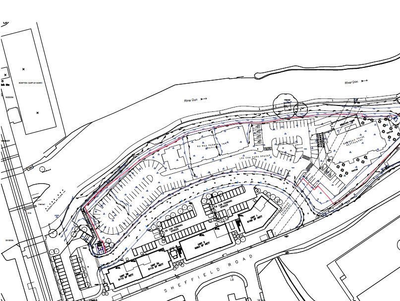
AECOM                                         Noise Ingress Assessment                                                              1

Capabilities on project:
Building Engineering

1          Introduction

1.1        A new Premier Inn is proposed on a site on the Phoenix Riverside industrial area in Rotherham. The hotel will be a new
           building situated next to offices, a busy road a railway line and other industrial premises.
1.2        AECOM Acoustics was commissioned to undertake an external noise survey and preliminary site review to identify likely
           noise control measures applicable to the new hotel.
1.3        An external noise survey was undertaken at the site to determine prevailing ambient noise levels at representative
           locations and times. Data from the survey was then used to determine sound reduction specifications for facades,
           glazing and ventilation apertures.
1.4        This report details the measured external noise levels, the design criteria and recommendations relating to noise control.
1.5        A glossary of the acoustic terms used in this report is given in Appendix A.
AECOM                                         Noise Ingress Assessment                                                                2

Capabilities on project:
Building Engineering

2          External Noise Survey

2.1        Introduction
2.1.1      This section provides details of the external noise survey undertaken on the 13th April 2011. Attended noise level
           measurements were made to determine prevailing ambient noise levels at representative locations and times on the
           proposed hotel site.
2.2        Site and Surroundings
2.2.1      The Phoenix Riverside site, proposed for the hotel is located between the River Don and Sheffield Road. Between the
           site and the road are existing office buildings and car parks. To the west of the site is a railway line approximately 200 m
           from the location of the proposed building and to the north, a smelting works was observed approximately 400 m away.

2.2.2      Figure 2.1 gives a site plan of the area showing the location of the building and the other key noise sources.

                                                                                   Smelting works

                           Railway Line

                                                                                       Sheffield Road

                                                                                                               N

                                                                                NOT TO SCALE

           Figure 1: Site Layout & Existing Noise Sources
AECOM Noise Ingress Assessment 3
Capabilities on project:
Building Engineering
2.2.3 Figure 2.1 shows the smelting works observed from the area of site proposed for the new hotel:
Figure 2: View Of The Smelting Works
2.2.4 Figure 2.3 shows the railway line observed from the area of the site proposed for the new hotel:AECOM Noise Ingress Assessment 4
Capabilities on project:
Building Engineering
Figure 3: View Of The Railway Line
2.3 Noise Measurements
2.3.1 Noise measurements were made to determine the noise incident upon the different facades of the hotel during noisiest
parts of the day (07:00 – 23:00) and night (23:00 – 07:00).
2.3.2 The noisiest parts of the day and night were considered to be morning rush hour (07:00 – 09:00) and the latter part of
the night (05:00 – 07:00).
2.3.3 Noise measurements were undertaken on parts of the site which represent the locations of the different facades of the
hotel. These locations were chosen to establish any variation in acoustic conditions for each facade. Figure 4 shows the
chosen measurement locationsAECOM Noise Ingress Assessment 5
Capabilities on project:
Building Engineering
Measurement
Location 2
Measurement
Location 1
Figure 4: Measurement Locations
2.4 Methodology
2.4.1 Attended noise level measurements were made at locations 1 and 2 during the noisiest parts of the day and night time
periods.
2.4.2 Table 2.1 lists the equipment used.
Equipment Item Serial Number
Rion NA-28 Sound Level Meter 570400
Rion NC-74 Sound Calibrator 34973231
Table 2.1: Survey Equipment
2.4.3 The sound level meter was field calibrated prior to and on completion of the survey period. No drift in calibration was
observed. Measurements were made in free-field conditions with the microphones placed approximately 1.5 m above
the ground at each location.
2.4.4 Measurement duration was 20 minutes.
2.4.5 Weather conditions at the start of the survey were 4°C and 75% RH with clear skies and a very light north-easterly wind.
These conditions were suitable for measurement of representative ambient and background noise levels at the site.AECOM Noise Ingress Assessment 6
Capabilities on project:
Building Engineering
2.5 Results
2.5.1 Table 2.2 gives a summary of the measured noise levels.
Measurement Location Start Time Noise Measurements
LAeq LAFmax
1 05:30 54 67
2 05:50 55 63
1 06:10 56 67
2 06:30 57 64
1 06:51 56 65
2 07:10 56 63
1 07:30 59 69
2 07:50 59 64
1 08:10 56 64
2 08:31 59 66
1 08:55 58 65
2 09:20 57 64
Values are sound pressure levels in dB re 20 µPa
Table 2.2: Summary of Measured Noise Levels
2.5.2 Of the above results, the LAeq levels are likely to dictate. They resulted from traffic noise on Sheffield Road, distant
motorway noise and noise from the distant smelting works.
2.5.3 During the day, background noise levels are dominated by traffic noise from Sheffield Road. However, from
approximately 06:00 onwards noise from the distant smelting works is clearly audible and provided some contribution to
the overall acoustic environment.
2.5.4 Although infrequent during the survey, freight train movements along the adjacent railway line generated audible short
term noise events, however the levels were not considered to be particularly high and not high enough to be considered
the cause of the measured maximum noise levels. Noise from this particular source was observed during the day and
night time period.
2.5.5 A full record of the survey results has been kept on file and will be supplied on request if required.AECOM Noise Ingress Assessment 7
Capabilities on project:
Building Engineering
3 Assessments
3.1 Noise Ingress to Guestrooms
3.1.1 Criteria
3.1.1.1 The Premier Inn Turnkey Specification requires that internal noise levels within guest rooms from external sources is
controlled to 35 dB LAeq during the day (07:00-23:00) and 30 dB LAeq during the night (23:00-0700). Furthermore, noise from
regular noise events should be controlled to 45 dB LAFmax during the night-time.
3.1.1.2 The specification also requires that noise associated with any other tenancy should not exceed NR20 L10 (23:00-07:00) within
guestrooms.
3.1.2 Assessment
3.1.2.1 Noise levels around the parts of the site proposed for the hotel are fairly consistent and subsequently the noise incident
on each facade will be similar. Therefore, one sound insulation specification has been determined applicable to all
facades of the proposed hotel.
3.1.2.2 The following sound insulation recommendations specifications must be achieved for each of the following facade
elements in order to achieve internal noise levels which meet the Premier Inn Generic Turnkey Specification:
3.1.3 Window Units
3.1.3.1 Window units including frames, seals and fixings must achieve the sound reduction indices given in Table 3.1.
Octave Band Centre Frequency (Hz)
63 125 250 500 1k 2k 4k 8k
Sound Reduction Index (dB R) 18 24 20 25 35 38 35 45
Table 3.1: Window Unit Sound Reduction Specification
3.1.3.2 The performance specification for windows should be achieved when measured in accordance with BS EN ISO 140-3 –
‘Laboratory measurement of airborne sound insulation of building elements’.
3.1.3.3 It is suggested that the supplier of the glazing provides suitable evidence of the window unit’s sound insulation. Typically
such evidence would take the form of a formal laboratory test report on the complete system.
3.1.3.4 The following glazing build-up would typically be required to meet the required sound reduction:
• 4 mm pane + 12 mm airgap + 4mm pane with suitable frame and seals
3.1.4 Trickle Ventilation
3.1.4.1 In terms of ventilation, the current preference for Premier Inns is to adopt a mechanical extract and supply system for
each guest room. However, if preferred, a natural ventilation system may be adopted using trickle ventilators for
background ventilation.
3.1.4.2 The following specification is based on one trickle ventilator unit used per guestroom. If greater numbers of units are
used per room the specification must be revised. The acoustic performance required for the single trickle ventilator
option is as follows:
Octave Band Centre Frequency (Hz)
63 125 250 500 1k 2k 4k 8k
Element Normalised Level
35 41 37 35 35 42 43 43
Difference dB (Dne)
Table 3.2: Trickle ventilator Sound Reduction SpecificationAECOM Noise Ingress Assessment 8
Capabilities on project:
Building Engineering
3.1.4.3 The performance specification for windows should be achieved when measured in accordance with BS EN ISO 140-10 –
‘Laboratory measurement of airborne sound insulation of small building elements’.
3.1.4.4 The above specification could typically be achieved with an RW Simon EHA acoustic trickle ventilator. However, many
other manufacturers offer products with equivalent performances.
3.1.5 External Wall
3.1.5.1 At this stage the proposals for the external wall construction are yet to be confirmed however, it is assumed that the
construction will comprise an SFS system including a twin layer of plasterboard on the inner leaf and a cementitious
render system on the outer element.
3.1.5.2 This arrangement is expected to be sufficient from a sound insulation perspective however an acoustic review of the
proposed construction should be undertaken during the forthcoming design stages.
3.2 Noise emission from the building to nearby noise sensitive receptors
3.2.1 It is our understanding that the Local Planning Authority have raised no concerns regarding the control of noise ingress
to the proposed development.
3.2.2 From our observations whilst on site and other research undertaken, no residential properties are in the proximity of the
proposed hotel. Therefore an assessment of building services in accordance with BS 4142 is not required.
3.2.3 However, noise and vibration from building services must be controlled in order to minimise the potential disturbance to
the users of the hotel. The following recommendations must be implemented.
• Noise from building services mounted on the roof must not exceed 50 dB LA at the edge of any part of the roof.
• The roof top plant must not be located directly above guestrooms and must be supported from major structural
elements of the building using appropriately selected anti-vibration mounts. The construction of the top floor roof
and ceiling must also be adequate to control ingress of the expected rooftop ambient plant noise levels. Current
design proposals show the roof top plant located above the central corridor not above guestrooms.
• Experience at other Premier in sites indicates that ambient noise levels on the roof might could exceed 70 dB LAeq.
To protect the rooms around the units from noise breaking via the roof a substantial construction will be required.
Ideally the roof structure should comprise concrete as opposed to a lightweight arrangement which would require
additional sound insulation measures to enhance its overall acoustic performance.
• The structural mounting conditions for items of rooftop plant must be sufficient to provide a level of vibration
isolation of at least 95 % at all frequencies of concern. This level of isolation provided by the ballast and insulation
alone however, in most cases proprietary spring isolators are required. Further design work will be required in the
forthcoming design stages to confirm the isolation requirements.
3.2.4 Despite no nearby noise sensitive receptors in close proximity to the proposed hotel, a building services noise limit has
been set to achieve appropriate internal noise levels within guestrooms, in accordance with the Premier Inn criteria.AECOM Noise Ingress Assessment 9
Capabilities on project:
Building Engineering
4 Conclusions
4.1 AECOM Acoustics have undertaken a noise survey and provided outline acoustic design recommendations for the
proposed Premier Inn, Rotherham. Noise level data measured at the site was used to determine the sound insulation
performance requirements for glazing and ventilation systems on different facades.
4.2 An external noise survey was undertaken on the 13th April 2011 to determine prevailing ambient noise levels at
representative times and locations. The site is subject to noise from Sheffield Road, a nearby railway line and a distant
smelting works. However none of the noise sources present any significant issues in terms of noise control.
4.3 Based on the results of the external noise survey, noise ingress predictions were undertaken to determine the sound
insulation performance requirements for glazing needed to meet the Premier Inn internal noise limit specifications.
4.4 Recommendations were given regarding the acoustic design of the hotel facades including sound insulation
performance specifications for glazing and trickle ventilation.
4.5 In the absence of any noise sensitive receptors in close proximity to the location of the proposed hotel, noise emission
limits for external building services were based on achieving a suitable external noise level at the facades of the hotel’s
guestrooms, to achieve internal noise levels in guestrooms in accordance with the Premier Inn criteria.AECOM Noise Ingress Assessment 10
Capabilities on project:
Building Engineering
Appendix A: Glossary of Acoustic Terms
This section provides a layperson’s explanation of the acoustics terms that commonly appear in reports. It is not intended to give
full scientific definitions and explanations or go into detail on how and why things are as they are. Some obsolete terms and
abbreviations have been included as they still appear in documents from time to time.
Jargon Buster
Many words have more specific meanings when used in acoustics than in every-day language.
sound is used to describe the physical phenomenon of the transmission of energy through gaseous or
liquid media via rapid fluctuations in pressure.
vibration is used to describe the transmission of energy through solid media by oscillation
level used solely to describe values measured in decibels
loudness is the human perception of the level of sound
noise has no strict definition and is often used interchangeably with sound however it is usually taken
to mean unwanted sound
index a value based on the mathematical processing of raw data
indicator a value used to indicate the likelihood of a particular response of effect
eg. L10,18hr is an index based on statistical processing of sound pressure data that is used as an
indicator for road traffic noise response.
weighted values modified to reflect sensitivities at particular frequencies.
apparent measured in situ
standardised a generalised value based on an in-situ measurement with a correction based on a space with
standard reverberation
normalised a generalised value based on an in-situ measurement with a correction based on space with
standard absorption area
insulation resistance to the passage of airborne sound
isolation resistance to the passage of vibration
insertion loss actual reduction in noise achieved by a structure or system in situ
dynamic insertion loss in a ducted system the actual reduction in sound achieved by an attenuator in real flow
conditions
static insertion loss in a ducted system the actual reduction in sound achieved by an attenuator in the absence of
fluid flow
attenuation amount by which sound or vibration is reduced when passing through a structure or system
directivity the amount by which a source radiates more sound in one direction than another.AECOM Noise Ingress Assessment 11
Capabilities on project:
Building Engineering
decibels The decibel is not a true measurement unit nor is it exclusive to acoustics.
dB The decibel is a logarithmic ratio of two values of a variable. Decibels are used because they
can represent very wide ranges of ratios (from trillionths and billionths to billions and trillions)
with a small range of decibel values. Decibels can be used to represent measured values by
using a known reference value in the ratio. When using decibels to measure something it is
therefore important to specify what variable is actually being measured and what reference
level has been used. This is done by adding a reference value statement in the form “dB re x
units”, where the units indicate the variable being measured and x is the reference value.
Decibels are used in acoustics because the human ear responds to sound in a logarithmic way
and the quantities measured in acoustics vary over wide ranges. However, decibels are used
in acoustics to measure several different things which it is important not to confuse with each
other.
To avoid confusion there is a notation system that identifies what a decibel value is for. The
notations take the form of an italic capital letter and some subscript characters. The capital
identifies the general type of value and the subscripts give specific details of what is being
represented.
Lxxx denotes a level (ie a value measured in dB by comparison with a reference
value);
Dxxx denotes a difference between two levels;
Rxxx denotes a rating (or index), which is measure of the generalised acoustic
performance of a material or construction based on a difference between two
levels;
Cxxx denotes a correction (or constant)
Of these only those with L notations require a reference value statement. Those with D or R
notations are effectively ratios of two measured values not one measured value and a
reference value and those with C notations are not based on reference values at all. A
reference value statement therefore has no meaning when describing D, R and C decibels.
Because decibels are logarithmic they have to be added, subtracted, multiplied, divided and
averaged using different techniques from normal numbers.
Sound Pressure Level This is the basic measure of how much sound there is at a given location. It is a measure of
Lp the size of the pressure fluctuations in the air that we perceive as sound.
Sound Pressure Level is expressed in decibels with a reference level of 20 µPa (Lp in dB re
obsolete – SPL 20 µPa)
Sound Power Level This is the total amount of sound produced by a source. It cannot be measured directly but it
LW can be calculated from Sound Pressure Level measurements in known conditions. It can be
obsolete – SWL used to predict the Sound Pressure Level at any point.
Sound Power Level is expressed in decibels with a reference level of 1 pW (LW in dB re 1 pW).
In the US a reference of 100 fW is sometimes usedAECOM Noise Ingress Assessment 12
Capabilities on project:
Building Engineering
Pitch, frequency The sound we perceive can have different characteristics. These can range from low-pitched
hums to high-pitched squeals and impulsive sounds.
In engineering acoustics the word frequency rather than pitch tends to be used when describing
the characteristics of a sound. The unit of frequency is the Hertz (Hz), which is the number of
pressure fluctuations per second.
Any sound can be defined by its frequency content. Some sounds comprise just one discrete
tonal sound frequency (tonal sounds). Others are distributed over wide frequency ranges (broad band
broadband sound sound). Impulsive sounds are made up short pulses of high frequency components. Sources
impulsive sound often produce all of these types of sound at the same time.
There are different ways of analysing and displaying the frequency content of a sound:
frequency analysis
Octave Band Analysis is the simplest method. The audible range of frequencies is
divided into 10 bands.
Third-Octave Band Analysis more detailed with 30 bands
Narrow Band Analysis 12th Octave (120 bands), 24th Octave (240),
Fast Fourier (FFT) Analysis a high resolution technique that can give extremely detailed
information on frequency content
The human ear does not sense all frequencies of sound equally. Our sensitivity is at a
maximum at around 2 kHz and steadily decreases above and below. Below 20 Hz and above
about 20 kHz we can’t hear at all.
A-weighting Within its operating limits a precision measurement microphone measures all frequencies the
same so the output it produces does not reflect what we would actually hear. The A-weighting
LA or LpA, LWA, is an electronic filter that matches the response of a sound level meter to that of the human ear.
When A-weighted the Sound Pressure Level Lp becomes LpA (or LA) and the Sound Power
Level LW becomes LWA.
It used to be common to identify that a level was A-weighted by writing dB(A) or dBA instead of
obsolete – dBA, dB(A) dB. These terms are now obsolete and should not be used as they conflict with other, non-
acoustic, uses of decibels
similar – C-weighting The response of the human ear varies depending on how loud the sound is. A-weighting
matches the response of a sound level meter to human hearing at low levels (~ 40-90 dB). For
LC or LpC, LWC
higher levels there are other weightings the most common of which is the C-weighting.
Noise Rating Sounds of different frequencies behave differently when they reflect from surfaces, pass
NR through partitions or deflect over barriers. These varying properties have to be considered
when making acoustic design decisions.
It is therefore sometimes appropriate, when specifying noise levels, to define limits in octave
bands rather than just an overall A-weighted level. Sometimes specifications for individual
octave bands are derived specifically for a given situation. In other situations it is appropriate to
use a standard set of octave band limits such as the Noise Rating Curves.
The Noise Rating for a measured sound spectrum is obtained by plotting the un-weighted
octave band levels on a set of NR curves. The NR value is the highest curve that is crossed by
any one octave band.
Noise Criterion (NC) curves are based on a similar principle but the curves are a slightly
similar – NC different shape. At low frequencies NC curves are lower in level than the equivalent NR curves.
Different types of decibels commonly used in acousticsAECOM Noise Ingress Assessment 13
Capabilities on project:
Building Engineering
Lp The instantaneous sound pressure level (Lp)
LpA (or LA) The A-weighted instantaneous sound pressure level (LpA or LA)
This is the root mean square size of the pressure fluctuations in the air. This level can fluctuate
wildly even for seemingly steady sounds. To make sound level meters easier to read the
values on the display are smoothed or damped out. This is effectively done by taking a rolling
average of the previous 0.125 s (FAST time constant) or the previous 1 s (SLOW time
constant).
LAF, LAS The letters F or S are added to the subscripts in the notation to indicate when the FAST or
SLOW time constant has been used. These are often omitted but it is good practice to include
them.
Lmax The maximum instantaneous sound pressure level (Lmax),
LAmax The A-weighted maximum instantaneous sound pressure level (LAmax)
LAFmax The A-weighted maximum instantaneous sound pressure level with a FAST time
constant (LAFmax).
This is the highest instantaneous sound pressure level reached during a
measurement period.
Lmin , LFmin The opposite of the Lmax is the minimum instantaneous sound pressure level or Lmin
etc.
It is good practice to include the letter which identifies the time constant used as this
can make a significant difference to the value.
Lpeak The peak sound pressure level (Lpeak)
LApeak , LCpeak The A (or C)-weighted peak sound pressure level (LApeak or LCpeak)
This is the size of the single largest pressure fluctuation during a measurement. It is different
from the LAmax as it is not based on the RMS value. This value is sometimes quoted as a peak
acoustic pressure in Pascals rather than a peak sound pressure level in dB re 20 µPa.
LN,T The percentage exceedence sound pressure level (LN,T),
LAN,T LAFN,T The A-weighted percentage exceedence sound pressure level (LAN,T), the A-weighted
N = %age value, 0-100
percentage exceedence sound pressure level with a FAST time constant (LAFN,T).
T = measurement time
This is the sound pressure level exceeded for N% of time period T. eg. If an A-
eg. LA90, LA10, LAF90, 5 min weighted level of x dB is exceeded for a total of 6 minutes within one hour, the level
will have been above x dB for 10% of the measurement period. This is written as
LA10,1hr = x dB.
LA0 (the level exceeded for 0 % of the time) is equivalent to the LAmax and LA100 (the
level exceeded for 100 % of the time) is equivalent to the LAmin.
It is good practice to include the letter which identifies the time constant used as this
can make a significant difference to the value.
Leq,T The equivalent continuous sound pressure level over period T (Leq,T),
LAeq,T The A-weighted equivalent continuous sound pressure level over period T (LAeq,T).
T = measurement time This is effectively the average sound pressure level over a given period. As the decibel is a
eg. LAeq,5min logarithmic quantity the Leq is not a simple arithmetic mean value.
The Leq is calculated from the raw sound pressure data. It is not appropriate to include a
reference to the FAST and SLOW time constants in the notationAECOM Noise Ingress Assessment 14
Capabilities on project:
Building Engineering
R The sound reduction index
This a measure of the sound insulation performance a material or construction
measured under laboratory conditions in accordance with BS EN ISO 140-3. R
differs from D in that it takes account of the area of the construction under test as well
as the absorption in the receiving room, both of these factors influence the measured
D. Taking into account these factors allows the R for different constructions to be
compared on a like for like basis. R values are quoted in third-octaves between ??
Hz and ?? Hz
Rw The weighted sound reduction index
A single value of the R derived from the third octave values of R using the method
described in BS EN ISO 717-1. Partitioning and building board manufacturers
commonly use this index to describe the inherent sound insulation performance of
their products.
Dne The normalised level difference of a building element
This is a measure of the acoustic performance of a discrete building element or such as a
trickle ventilator. The level difference is established within a laboratory and normalised to a
2
reference area of absorption which is 10m .You can also read