2740/42 Fifth St Passive House aka "Urban Green" Project Documentation - Passivhaus Planer
←
→
Page content transcription
If your browser does not render page correctly, please read the page content below
2740/42 Fifth St Passive House
                         aka “Urban Green”

Project Documentation

1         Abstract

    New residential duplex, constructed in 2017, in Victoria, BC (Canada)

      Project Documentation       Page 1 of 36                   04 / 2018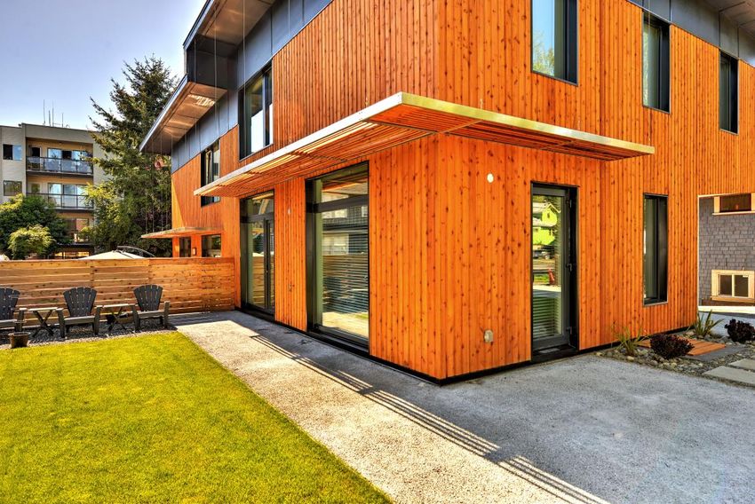
1.1       Data of building / Gebäudedaten
Year of construction/         2017
Baujahr
U-value external wall/        0.135 – 0.156
                                                   Space heating /
                                                   Heizwärmebedarf
                                                                                                15
                                                                                              kWh/(m²a)
U-Wert Außenwand              W/(m²K)
U-value basement ceiling/                          Primary Energy Renewable (PER) /
                          0.128 W/(m²K)                                                     58 kWh/(m²a)
U-Wert Kellerdecke                                 Erneuerbare Primärenergie (PER)
U-value roof/                                      Generation of renewable energy /
                              0.110 W/(m²K)                                                  0 kWh/(m²a)
U-Wert Dach                                        Erzeugung erneuerb. Energie
U-value window/                                    Non-renewable Primary Energy (PE) /
                              0.79 W/(m²K)                                                  130 kWh/(m²a)
U-Wert Fenster                                     Nicht erneuerbare Primärenergie (PE)
Heat recovery/                                     Pressure test n50 /
                              77 %                                                              0.3 h-1
Wärmerückgewinnung                                 Drucktest n50
Special features/
                              Heat recovery from all shower drain water, permeable concrete paved surfaces
Besonderheiten

 1.2        Brief Description
 This building is a front/back style residential duplex, with each unit consisting of two
 storeys. The front unit is 118 sqm, the rear is 126 sqm, and they are essentially a
 mirror image of each other. The owners built this building for their own use. They
 chose a duplex because it was permitted in the local Zoning, and the current market
 conditions make income-generating properties more feasible for young urban
 professionals near the City centre.
 After seeing the Austria House in Whistler during the 2010 Olympics, the owners were
 interested in the Passive House principles, but were wary about assembling a building
 in another region and shipping it for assembly. They wanted to build to a high standard
 of energy efficiency while utilizing local and traditional construction practices as much
 as possible, rather than doing something that was new and unfamiliar for everyone
 involved.
 The Passive House principles were all adopted: high levels of insulation, air-tight
 construction, high-performance windows and doors, a heat-recovery ventilation
 system, elimination of thermal bridging through well-designed building assembly
 details, and proper building orientation to make use of solar gains and shading. The
 building stretches its length from East to West, enabling notable solar gains from it’s
 Southern exposure.

      Project Documentation                      Page 2 of 36                                 04 / 2018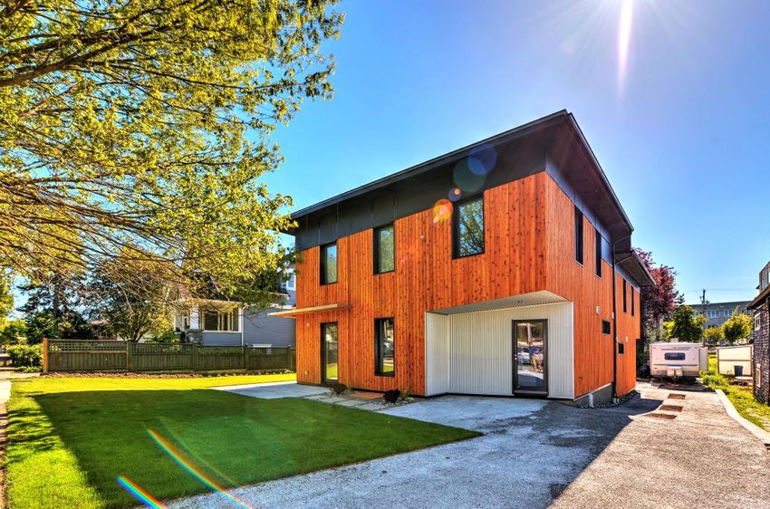
1.3         Responsible project participants /
            Verantwortliche Projektbeteiligte

Architect/                    Cascadia Architects
Entwurfsverfasser             http://cascadiaarchitects.ca/
Implementation planning/      Adapt Energy Advising, Cascadia Architects, Interactive Construction
Ausführungsplanung            https://www.adaptenergyadvising.com/
                              http://cascadiaarchitects.ca/
                              https://www.interactiveconstruction.ca/
Building systems/             Adapt Energy Advising, Cascadia Architects, Interactive Construction
Haustechnik                   https://www.adaptenergyadvising.com/
                              http://cascadiaarchitects.ca/
                              https://www.interactiveconstruction.ca/
Structural engineering/       Hoel Engineering
Baustatik                     http://www.hoel.bc.ca/
Building physics/             Cascadia Architects
Bauphysik                     http://cascadiaarchitects.ca/
Passive House project         Adapt Energy Advising
planning/                     https://www.adaptenergyadvising.com/
Passivhaus-Projektierung
Construction management/      Interactive Construction
Bauleitung                    https://www.interactiveconstruction.ca/

Certifying body/              Andrew Peel
Zertifizierungsstelle         http://www.peelpassivehouse.ca/
                                  17774-    Project-ID (www.passivehouse-database.org)
Certification ID/              17775_APC_P
Zertifizierungs ID                                                                                   5717
                               H_20180313_A Projekt-ID (www.passivehouse-database .org)
                                    P

                                                 Reed Cassidy
Author of project documentation /
                                                 Adapt Energy Advising
Verfasser der Gebäude-Dokumentation

Date, Signature/                                 29 April 2018
Datum, Unterschrift

  Project Documentation                     Page 3 of 36                                 04 / 2018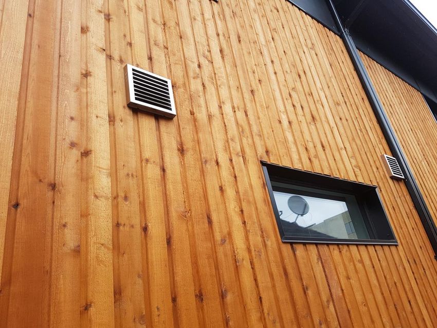
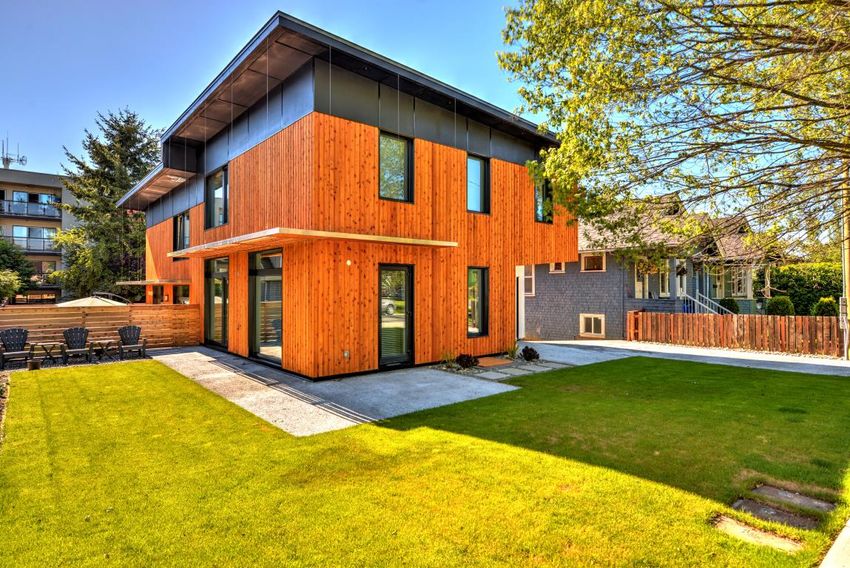
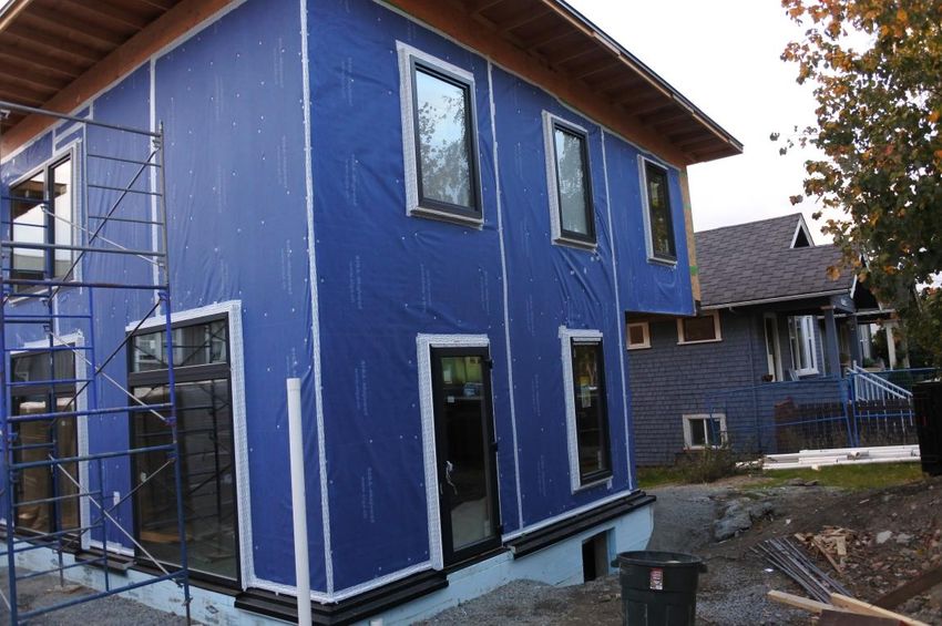
2           Exterior Views

View from North West; front door entry in recessed area.

View from South West; large South windows shown, as well as front yard.

    Project Documentation          Page 4 of 36                           04 / 2018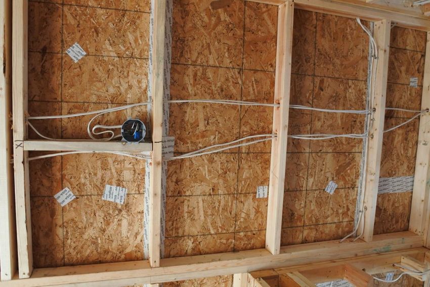
South West; building shading element highlighted. Pervious concrete used for all
paved surfaces.

West unit interior; open concept living area on main floors.

  Project Documentation              Page 5 of 36                          04 / 2018
East unit kithcen; re-used demolitioned building‘s subfloor for kitchen trim.

East unit master ensuite bathroom; electronic heated floors controlled by smart
unit provide majority of active heating system.

  Project Documentation               Page 6 of 36                              04 / 2018
3 Cross-Section
Cross-section running East to West.
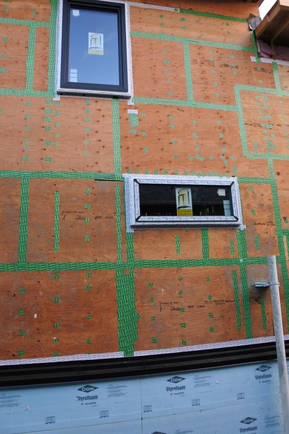
Exterior wall insulation (6“ Roxul CavityRock) eliminates most thermal bridging at
assembly junctions, especially around fenestration units where the insulation laps
over the window-to-wall and door-to-wall junctions.
Exterior wall assembly, horizontal section.
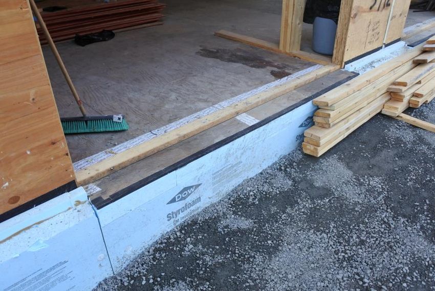
Additional insulation added to the foundation wall exterior minimizes thermal bridging
at the main-floor to foundation wall junction. This particular thermal bridge required
consideration, because it‘s the geatest linear distance of any in the building.
1“ XPS insulation was added on top of the subfloor beneath the concrete skim-coat
to improve the RSI value of the crawlspace ceiling, as well as to minimize thermal
bridging from the floor joists. Also, the heavily insulated crawlspace creates a
Project Documentation Page 7 of 36 04 / 2018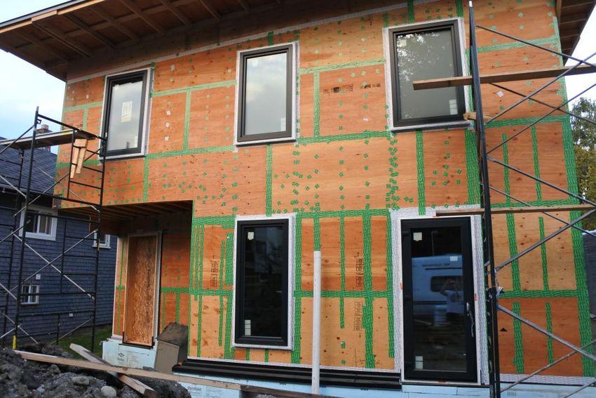
buffered area for the thermal floor assembly above, which has the added benefit of
keeping the concrete floors warmer to the touch.

Main floor assembly, crawlspace ceiling.

A dropped 2x4 ceiling below the roof trusses enables a more continuous roof air
barrier, as well as reducing thermal bridging from the roof trusses.

Top of wall at roof.

  Project Documentation              Page 8 of 36                           04 / 2018
4           Floor Plans

First and second storey floor plans.

    Project Documentation          Page 9 of 36   04 / 2018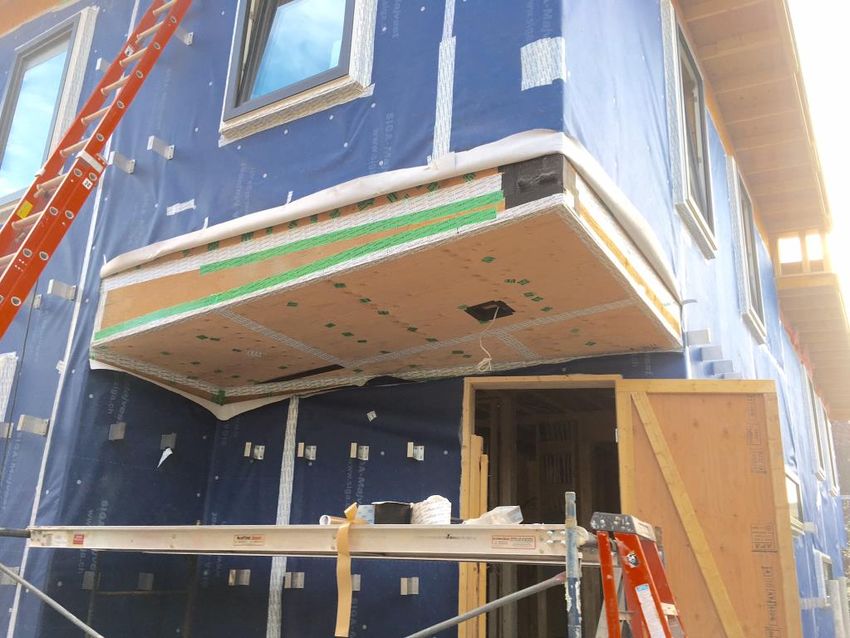
West unit first storey.

An open concept living area maximizes the open interior feeling of space, which is
typical for modern construction in this area.

A large storage / service room is located on main floor, as no attached garage was
implemented. The domestic water heater and shower water heat re-capture system
are located here, as well as the HRV.

  Project Documentation             Page 10 of 36                            04 / 2018
West unit second storey.

Three bedrooms, two bathrooms, and laundry facilites located on the second floor. A
ductless condensing clothes dryer is provided in each unit.

  Project Documentation             Page 11 of 36                          04 / 2018
5           Building Construction Details
5.1.1. Floor Assembly – Crawlspace Ceiling

U-Value: 0.128 W/(m2*K)

38 mm concrete top coat
25 mm XPS insulation
19 mm plywood sheathing
300 mm TJI @ 400 mm floor joists
R40 batt insulation

5.1.2. Floor Assembly – Covered
Entry
U-Value: 0.128 W/(m2*K)

13 mm wood flooring
19 mm plywood sheathing
300 mm TJI @ 400 mm floor joists
R40 batt insulation
R20 batt insulation dropped assembly

5.3.1. Wall Assembly

U-Value: 0.156 W/(m2*K)

13 mm gypsum board
R14 Batt insulation
38 mm x 89 mm @ 400 mm wood
studs
13 mm plywood sheathing
Siga Majvest weather barrier
150 mm Roxul CavityRock insulation
w/ z-grit clips
38 mm x 89 mm horizontal strapping
19 mm cedar siding

    Project Documentation            Page 12 of 36   04 / 2018
5.3.2. Wall Assembly – North Wall U-Value: 0.135 W/(m2*K) 13 mm gypsum board R14 Batt insulation 38 mm x 140 mm @ 400 mm studs 13 mm plywood sheathing Siga Majvest weather barrier 150 mm Roxul CavityRock insulation, w/ z-grit clips 38 mm x 89 mm horizontal strapping 19 mm cedar siding 5.4 Roof Assembly U-Value: 0.110 W/(m2*K) 13 mm gypsum board 38 mm x 89 mm @ 400 mm drop ceiling joists R14 batt insulation 13 mm OSB sheathing 406 mm @ 400 mm trusses 2 layer R28 batt insulation 13 mm plywood sheathing Torch-on roofing membrane One roof, two floor, and two wall assemblies were used in this project. The desire was to install as much exterior insulation as possible, which was achievable in most of the assemblies. The local jurisdiction allowed 6” of exterior wall assembly projection into required setbacks, which didn’t have great benefit for this project due to the ample lot size, but was a nice option to have. Project Documentation Page 13 of 36 04 / 2018
5.4 Thermal Bridge Details

5.4.1. Z-grit Clips

The steel z-grit clips used to contain the exterior Roxul insulation required 3D
modelling. The resulting Chi-value was 0.007 W/(m2*k).

Heat 3D model

Z-grit clips and insulation. The clips proved easy to install, and didn’t create any
air leakage during testing. They are a sturdy base for the cedar & cement fibreboard
cladding.

  Project Documentation               Page 14 of 36                            04 / 2018
5.4.2. Window Junctions

Sills for floor to ceiling windows and doors received notches in the concrete, which
were framed with plywood and filled with XPS insulation. This prevented the
fenestration units from being framed onto concrete foundations, thus minimizing Psi-
values.

All window & door headers & jambs were overlapped with exterior insulation. 2D
THERM modelling was done, and yielded a Psi-value of 0.006 W/(m2*K).

THERM models for window jambs.

  Project Documentation             Page 15 of 36                           04 / 2018
West unit dining room window, pre cladding. Framing around windows protected
insulation and provided support from metal window trim.

5.4.3. First floor to Foundation Wall

Two THERM models were done to determine the heat loss through this junction.

  Project Documentation             Page 16 of 36                        04 / 2018
THERM model for heat loss to basement. Psi-Value: 0.073 W/(m2*K)

THERM model heat heat loss to exterior. Psi-Value: -0.032 W/(m2*K)

  Project Documentation          Page 17 of 36                       04 / 2018
6           Windows
Victoria, BC is located in climate zone 4 (warm-temperate). This has Victoria seeing
relatively mild winters and summers.

Euroline windows were used for all window and doors except for the front doors.
They are triple-pane, insulated vinyl-frame windows, and PHI certified components.
The solar factor (g) selected was high in order to make the most of the beneficial
exposure, and wasn’t of too much concern regarding heat loss.

East unit living room window. All window swing and tilt inward.

Window sill rough framing at foundation buck assembly.

    Project Documentation           Page 18 of 36                           04 / 2018
Euroline product performance chart. The windows were installed in exterior sub-frames to better align the units in the plane of insulation. The exterior insulation was also wrapped over the frames to minimize thermal bridging. West unit master bderoom window. Window sits a few inches proud of wall. Project Documentation Page 19 of 36 04 / 2018
7           Doors
Optiwin Entrada doors were used for entry doors. They are triple-pane, insulated
wood fram doors, and are PHI certified components. They were chosen for this
location due to their flush door sill, and their elegant feel and appearance. The cost
of Optiwin products limited them to the one appliction for this project.

The doors were all installed at walk-out elevation, in order to avoid installing decks
with their assocated thermal bridges.

Optiwin product performance chart.

East unit fornt door opened.

    Project Documentation             Page 20 of 36                             04 / 2018
East unit front door. Project Documentation Page 21 of 36 04 / 2018
8           Airtightness
8.1       Methods and Photos

The air barrier approach was selected based on owner preference. The primary
system incorporates wood products, as they‘re easy to manage accidental
penetrations, and they were already being used in most of the construction
assemblies. Also, plywood‘s vapour permeability qualities make it a desirable choice
for this coastal climate.

The plywood subfloor of the first floor (above the unheated crawlspace) runs
continuously under the exterior wall plates, which enables it to be taped to the
plywood wall sheathing. All joints and penetrations were sealed with Siga tape.

Bathroom floor; penetrations and plywood joints sealed.

    Project Documentation            Page 22 of 36                           04 / 2018
Service room floor; penetrations ad plywood joints sealed. The plywood wall sheathing saw all joints and penetrations sealed with Siga tape. The plywood subfloor and the OSB roof system air barrier (shown later) were sealed to the wall sheathing with Siga tape. Wall sheathing sealing. Taped and sealed. Second floor overhang air barrier installed. Project Documentation Page 23 of 36 04 / 2018
The windows were installed in an exterior subframe, with all connections between
sheathing, subframe, and window frame being sealed with Siga tape.

Windows installed and air barrier system installed.

When the weather barrier was contemplated, Siga Majvest was selected. It was a
good product to work with on site, as it wasn’t prone to tearing. In addition, it’s
vapour permeability are higher than typical local products such as Tyvek, which
make it a good choice for coastal BC climates.

Once installed, it’s joints and penetrations were also sealed to help improve the wall
air barrier system.

  Project Documentation              Page 24 of 36                             04 / 2018
Weather barrier membrane, installed and sealed.

Windows sealed to Siga weather barrier.

 Project Documentation           Page 25 of 36    04 / 2018
The underside of the roof trusses saw a layer of OSB, with all joints and penetrations
sealed. The OSB runs continuously under the roof trusses and on top of th ewall
plates, eneabling it to be sealed to the wall sheathing. To maintain air barrier
continuity (and incorporate additional thermal barrier conuitiy as well), a dropped
ceiling was installed to house all services and electrical equipment. This reduced the
roof air barrier penetrations to one plumbing vent and two wire penetrations in each
unit.

Roof assembly air barrier and dropped ceiling.

8.2      Final Blower Door Testing Results

The completed building achieved the following results:

                                                              n50
                          East Unit (Front)             West Unit (Rear)   Average for Building
      Combined Results          0.34                         0.34                 0.34
        Pressurization         0.3256                       0.2243
      Depressurization         0.3446                       0.3415

  Project Documentation                 Page 26 of 36                                  04 / 2018
9 Ventilation
A Passive House certified ventilation unit was specified in each unit.
Ventilation unit: Zehnder Comfoair 350
Whole system efficiency (PHPP): 77%
Electrical efficiency: 0.29 Wh/m3
Each unit uses Zehnder ComfoTube ducting, and a manifold. This system was easy
to install, which was completed by the owner and the carpenters. It was favoured by
the owners because it didn’t require the contracting of a sheet metal installer for duct
work, rather the ducts were fed through the building to each room as directed by the
manufacturer’s design team.
West unit HRV. East unit HRV.
West unit upper bathroom ducting and room connection.
Project Documentation Page 27 of 36 04 / 2018The ventilation control units are locted in the hallway between the entry foyer and the the kitchen. Zehnder Comfo Controller. The service room was designed to be on the North side, so the HRV supply and exhaust ducts would have better summer time cooling effectiveness. Supply and exhaust openings in building exterior wall. North side. Project Documentation Page 28 of 36 04 / 2018
10        Heating
Due to the low heating load enabled by Passive House buildings, combined with the
source of all local electricity being from hydro-electric dams, the owners selected
electrical resistance for the active heating source. In addition, electricity was the
chosen fuel source because the owners plan to install a photovoltaic array in the
future, which will offset heating energy consumed.

Upper floor bathroom electrically heated floors. Typical to all upper floor
bathrooms.

Smart control devices installed to individually control each heated bathroom
floor.

  Project Documentation              Page 29 of 36                            04 / 2018
West unit master bathroom tiled floor (heating cables beneath).

East unit living room wall mounted convection heater.

  Project Documentation           Page 30 of 36                   04 / 2018
11        Domestic Hot Water

Domestic hot water is supplied to each
unit by an electrically powered
residential storage tank. Rheem
Marathon tanks were selected for their
reliability and lifetime warranty, as well
as thier high level of tank insulation.

Electricity was chosen as a fuel source
because the owners plan to install a
photovoltaic array in the future.

                                                    To supplement the water heater, each
                                                    tank is connected to a heat recapture
                                                    system that is plumbed from the
                                                    shower drains. A Dutch Solar Systems
                                                    model 800 was chosen, as it was a
                                                    product recognized by PHI. This was
                                                    an easy addition to incorporate, as the
                                                    building was being built new and the
                                                    plumbing could be installed as desired.

                                                    These systems are also an easy way
                                                    to make energy gains without any
                                                    complex systems or components.

  Project Documentation                 Page 31 of 36                             04 / 2018
12 PHPP Verification Sheet
Passive House Verification
Photo or Drawing Building: Blake | Cassidy Passive House
Street: 2740/42 Fifth Street
Postcode/City: V8T 4B2 Victoria
Province/Country: BC CA-Canada
Building type: Duplex Residence
Climate data set: CA0025a-Victoria
Climate zone: 4: Warm-temperate Altitude of location: 15.25 m
Home owner / Client: Aneesa Blake and Reed Cassidy
Street: 2740 Fifth Street
Postcode/City: V8T 4B2 Victoria
Province/Country: BC
Architecture: Cascadia Architects Inc. Mechanical system:
Street: 1060 Meares Street Street:
Postcode/City: Victoria V8V 3J6 Postcode/City:
Province/Country: BC CA-Canada Province/Country:
Energy consultancy: Certification:
Street: Street:
Postcode/City: Postcode/City:
Province/Country: Province/Country:
Year of construction: 2016 Interior temperature winter [°C]: 20.0 Interior temp. summer [°C]: 25.0
No. of dwelling units: 2 Internal heat gains (IHG) heating case [W/m 2]: 2.5 IHG cooling case [W/m²]: 2.6
No. of occupants: 5.4 Specific capacity [Wh/K per m² TFA]: 60 Mechanical cooling:
Specific building characteristics with reference to the treated floor area
Alternative
Treated floor area m² 243.7 Criteria criteria Fullfilled?2
Space heating Heating demand kWh/(m²a) 15 ≤ 15 -
yes
Heating load W/m² 11 ≤ - 10
Space cooling Cooling & dehum. demand kWh/(m²a) - ≤ - -
-
Cooling load W/m² - ≤ - -
Frequency of overheating (> 25 °C) % 0 ≤ 10 yes
Frequency excessively high humidity (> 12 g/kg) % 0 ≤ 20 yes
Airtightness Pressurization test result n50 1/h 0.3 ≤ 0.6 yes
Non-renewable Primary Energy
PE demand kWh/(m²a) 130 ≤ - -
(PE)
PER demand kWh/(m²a) 58 ≤ 60 60
Primary Energy
Renewable (PER) Generation of renewable yes
kWh/(m²a) 0 ≥ - -
energy
2
Empty field: Data missing; '-': No requirement
PHPP Verification Sheet
Project Documentation Page 32 of 36 04 / 2018Heating energy balance calculated using PHPP Window solar gains more than doubled energy losses, which eneabled the building to have more windows on the Northern face and improve natural lighting. Thermal bridge losses were kept low, which is plausible for relatively less complicated new small residential buildings. Ventilation losses were high, due to longer than desired interior supply & exhaust duct lengths. Project Documentation Page 33 of 36 04 / 2018
13        User Experience and Actual Consumption
This building has been occupied by the owners (East side) and the same tenants
(West side) for the first year of it’s operation.

In this region, all of the electricity is provided by BC Hydro. BC Hydro creates
electricity using hydro-electric dams. During the first year of operation, the following
data was obtained for the total energy consumption (all electricity).

        BILLING PERIOD           EAST UNIT ENERGY USED         WEST UNIT ENERGY USED
                                         (kWh)                         (kWh)
 Mar 21, 2017 – May 24, 2017              1087
  Apr 1, 2017 – May 24, 2017                                             1114
 May 25, 2017 – July 24, 2017              906                           1277
 July 25, 2017 – Sept 22, 2017             952                           1052
 Sept 23, 2017 – Nov 23, 2017              1051                          1459
  Nov 24, 2017 – Jan 23, 2018              1833                          1730
  Jan 24, 2018 – Mar 23, 2018              1549
  Jan 24, 2018 – Mar 31, 2018                                            1809
    TOTAL ANNUAL ENERGY                    7378                          8441
        CONSUMPTION

Total energy used during first year:    64.86 kWh/m2*a (15,819 kWh/a)
PHPP Non-Renewable Primary Energy (PE): 129.9 kWh/m2*a (31,684 kWh/a)
PHPP Primary Energy Renewable (PER):    58.4 kWh/m2*a (14,244 kWh/a)

For comparison, the 1970’s era single-family dwelling with secondary suite to the
North of this home was using approximately 3 x as much electricity during the mid-
winter months. This sample home heated exclusively with baseboard heaters.

The West unit experiences higher interior temperatures in the summer months than
the East unit, as the heat from setting sun radiates through the windows. The interior
temprature rarely breaks 25 Celsuis, thanks to the HRV operation in bypass mode
and the summer nighttime ventilation as shown in the PHPP. The owners are
contemplating installing exterior blinds on the upper floor West windows to improve
interior comfort.

Upon move-in, during the first few days of living in a Passive House building, the
owners became immediately aware of the interior comfort. Exterior noise is minimal.
Interior air is always fresh. Odors don’t linger for very long. Interior surfaces during
the winter time are notably warm, compared to a typical home. The owners prefer
their home to staying in hotels, as their Passive House home is far more comfortable.

  Project Documentation               Page 34 of 36                             04 / 2018
14 Cost Considerations
For reference, here is some building criteria:
• 244 sqm (approx. 3050 sqft) floor area, 2 storey, unheated crawlspace, wood-
framed construction
• Permeable concrete driveway & patios
• 24 total fenestration units, 2 water heaters, 2 HRV systems
• 2 dwelling units; entire building contains 6 bedrooms, 4 bathrooms, 2 powder
rooms, 2 kitchens, 2 living & dining rooms, 2 laundry areas, 2 service rooms
The total construction costs were as follows:
To get an idea of costs required to achieve Passive House certifiation, we analyzed
the wall assembly. This seemed like a good analysis, because wall assemblies are
commonly compared in this region. It was assumed that a regular building will
receive:
• Gypsum wall board
• Lumber framing
• Batt insulation
• Plywood sheathing
• Tyvek weather barrier
• Rainscreen strapping
• Cladding
Assuming the aforementioned traditional wall assembly, we’ve calculated the added
cost of:
• Upgrading from Tyvek to Majvest
• Taping plywood joints and penetrations with Siga tape
• Taping Majvest joints and penetrations with Siga tape
• Installing ACS clips
• Installing Roxul CavityRock
• Installing external framing to support cladding
Project Documentation Page 35 of 36 04 / 2018Given these cost analysis parameters:
• The added cost for the Passive House exterior wall system was $10.50 / sqft.
• The added cost to the overall construction cost for the project was $39,000, or
4.2% of the grand total.
It was estimated that the total added cost to build to Passive House standards was
approximately 18% above Building Code minimum.
Project Documentation Page 36 of 36 04 / 2018You can also read