9 ROBOT CONSTRUCTION RULES - NET
←
→
Page content transcription
If your browser does not render page correctly, please read the page content below
2021 FIRST® Robotics Competition

9 ROBOT CONSTRUCTION RULES

This section of the 2021 FIRST® Robotics Competition Game Manual presents rules relevant to the
construction of a 2021 FIRST Robotics Competition ROBOT. ROBOTS must pass Inspection at each
FIRST Robotics Competition event to confirm compliance before being allowed to compete in a
Qualification or Playoff MATCH, per Inspection & Eligibility Rules.

9.1     Overview
The rules listed below explicitly address legal parts and materials and how those parts and materials may
be used on a 2021 ROBOT. A ROBOT is an electromechanical assembly built by the FIRST Robotics
Competition team to play the current season’s game and includes all the basic systems required to be an
active participant in the game –power, communications, control, BUMPERS, and movement about the
FIELD.

There are many reasons for the structure of the rules, including safety, reliability, parity, creation of a
reasonable design challenge, adherence to professional standards, impact on the competition, and
compatibility with the Kit of Parts (KOP). The KOP is the collection of items listed on the 2020 and 2021
Kickoff Kit checklists, distributed to the team via FIRST Choice in the 2020 and/or 2021 season, or paid
for completely (except shipping) with a Product Donation Voucher (PDV) from the 2020 and/or 2021
season.

Another intent of these rules is to have all energy sources and active actuation systems on the ROBOT
(e.g. batteries, compressors, motors, servos, cylinders, and their controllers) drawn from a well-defined
set of options. This is to ensure that all teams have access to the same actuation resources and that the
Inspectors are able to accurately and efficiently assess the legality of a given part.

ROBOTS are made up of COMPONENTS and MECHANISMS. A COMPONENT is any part in its most
basic configuration, which cannot be disassembled without damaging or destroying the part or altering its
fundamental function. A MECHANISM is a COTS or custom assembly of COMPONENTS that provide
specific functionality on the ROBOT. A MECHANISM can be disassembled (and then reassembled) into
individual COMPONENTS without damage to the parts.

Many rules in this section reference Commercial-Off-The-Shelf (COTS) items. A COTS item must be a
standard (i.e. not custom order) part commonly available from a VENDOR for all teams for purchase. To
be a COTS item, the COMPONENT or MECHANISM must be in an unaltered, unmodified state (with the
exception of installation or modification of any software). Items that are no longer commercially available
but are functionally equivalent to the original condition as delivered from the VENDOR are considered
COTS and may be used.

        Example 1: A team orders two (2) ROBOT grippers from RoboHands Corp. and receives
        both items. They put one in their storeroom and plan to use it later. Into the other, they
        drill “lightening holes” to reduce weight. The first gripper is still classified as a COTS item,
        but the second gripper is now a FABRICATED ITEM, as it has been modified.

        Example 2: A team obtains openly available blueprints of a drive module commonly
        available from Wheels-R-Us Inc. and has local machine shop “We-Make-It, Inc.”
        manufacture a copy of the part for them. The produced part is NOT a COTS item,
        because it is not commonly carried as part of the standard stock of We-Make-It, Inc.

                                                                                 9 ROBOT Construction Rules
                                                                                                         V1
                                                                                                  69 of 113
2021 FIRST® Robotics Competition

        Example 3: A team obtains openly available design drawings from a professional
        publication during the pre-season, and uses them to fabricate a gearbox for their ROBOT
        during the build period following Kickoff. The design drawings are considered a COTS
        item, and may be used as “raw material” to fabricate the gearbox. The finished gearbox
        itself would be a FABRICATED ITEM, and not a COTS item.

        Example 4: A COTS part that has non-functional label markings added would still be
        considered a COTS part, but a COTS part that has device-specific mounting holes added
        is a FABRICATED ITEM.

        Example 5: A team has a COTS single-board processor version 1.0, which can no longer
        be purchased. Only the COTS single-board processor version 2.0 may be purchased. If
        the COTS single-board processor version 1.0 is functionally equivalent to its original
        condition, it may be used.

        Example 6: A team has a COTS gearbox which has been discontinued. If the COTS
        gearbox is functionally equivalent to its original condition, it may be used.

A VENDOR is a legitimate business source for COTS items that satisfies all the following criteria:

          A. has a Federal Tax Identification number. In cases where the VENDOR is outside of the
             United States, they must possess an equivalent form of registration or license with the
             government of their home nation that establishes and validates their status as a legitimate
             business licensed to operate within that country.
          B. is not a “wholly owned subsidiary” of a FIRST Robotics Competition team or collection of
             teams. While there may be some individuals affiliated with both a team and the VENDOR,
             the business and activities of the team and VENDOR must be completely separable.
          C. must be able to ship any general (i.e., non-FIRST unique) product within five business days
             of receiving a valid purchase request. It is recognized that certain unusual circumstances
             (such as 1,000 FIRST teams all ordering the same part at once from the same VENDOR)
             may cause atypical delays in shipping due to backorders for even the largest VENDORS.
             Such delays due to higher-than-normal order rates are excused.
          D. should maintain sufficient stock or production capability to fill teams’ orders within a
             reasonable period during the season (less than 1 week). (Note that this criterion may not
             apply to custom-built items from a source that is both a VENDOR and a fabricator. For
             example, a VENDOR may sell flexible belting that the team wishes to procure to use as
             treads on their drive system. The VENDOR cuts the belting to a custom length from
             standard shelf stock that is typically available, welds it into a loop to make a tread, and
             ships it to a team. The fabrication of the tread takes the VENDOR two weeks. This would
             be considered a FABRICATED ITEM, and the two-week ship time is acceptable.)
             Alternately, the team may decide to fabricate the treads themselves. To satisfy this
             criterion, the VENDOR would just have to ship a length of belting from shelf stock (i.e. a
             COTS item) to the team within five business days and leave the welding of the cuts to the
             team.
          E. makes their products available to all FIRST Robotics Competition teams. A VENDOR must
             not limit supply or make a product available to just a limited number of FIRST Robotics
             Competition teams.

        The intent of this definition it to be as inclusive as possible to permit access to all
        legitimate sources, while preventing ad hoc organizations from providing special-purpose
        products to a limited subset of teams in an attempt to circumvent the cost accounting
        rules.

                                                                             9 ROBOT Construction Rules
                                                                                                     V1
                                                                                              70 of 113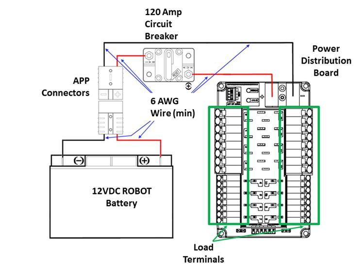
2021 FIRST® Robotics Competition

        FIRST desires to permit teams to have the broadest choice of legitimate sources
        possible, and to obtain COTS items from the sources that provide them with the best
        prices and level of service available. Teams also need to protect against long delays in
        availability of parts that will impact their ability to complete their ROBOT. The build
        season is brief, so the VENDOR must be able to get their product, particularly FIRST
        unique items, to a team in a timely manner.

        Ideally, chosen VENDORS should have national distributors (e.g. Home Depot, Lowes,
        MSC, McMaster-Carr, etc.). Remember, FIRST Robotics Competition events are not
        always near home – when parts fail, local access to replacement materials is often
        critical.

A FABRICATED ITEM is any COMPONENT or MECHANISM that has been altered, built, cast,
constructed, concocted, created, cut, heat treated, machined, manufactured, modified, painted, produced,
surface coated, or conjured partially or completely into the final form in which it will be used on the
ROBOT.

        Note that it is possible for an item (typically raw materials) to be neither COTS nor a
        FABRICATED ITEM. For example, a 20 ft. (~610 cm) length of aluminum which has been
        cut into 5 ft. (~152 cm) pieces by the team for storage or transport is neither COTS (it’s
        not in the state received from the VENDOR), nor a FABRICATED ITEM (the cuts were
        not made to advance the part towards its final form on the ROBOT).

Teams may be asked to provide documentation proving legality of non-2020 or 2021 KOP items during
Inspection where a rule specifies limits for a legal part (e.g. pneumatic items, current limits, COTS
electronics, etc.).

Some of these rules make use of English unit requirements for parts. If your team has a question about a
metric-equivalent part’s legality, please e-mail your question to frcparts@firstinspires.org for an official
ruling. To seek approval for alternate devices for inclusion in future FIRST Robotics Competition seasons,
please contact frcparts@firstinspires.org with item specifications.

Teams should acknowledge the support provided by the corporate Sponsors and mentors with an
appropriate display of their school and Sponsors names and/or logos (or the name of the supporting
youth organization, if appropriate).

FIRST Robotics Competition can be a full-contact competition and may include rigorous game play. While
the rules aim to limit severe damage to ROBOTS, teams should design their ROBOTS to be robust.

9.2     General ROBOT Design
R1. The ROBOT (excluding BUMPERS) must have a FRAME PERIMETER, contained within the
    BUMPER ZONE and established while in the ROBOT’S STARTING CONFIGURATION, that is
    comprised of fixed, non-articulated structural elements of the ROBOT. Minor protrusions no greater
    than ¼ in. (~6 mm) such as bolt heads, fastener ends, weld beads, and rivets are not considered part
    of the FRAME PERIMETER.

        To determine the FRAME PERIMETER, wrap a piece of string around the ROBOT
        (excluding BUMPERS) at the BUMPER ZONE described in R18 and pull it taut. The
        string outlines the FRAME PERIMETER.

        Example: A ROBOT’S chassis is shaped like the letter ‘V’, with a large gap between
        chassis elements on the front of the ROBOT. When wrapping a taut string around this

                                                                             9 ROBOT Construction Rules
                                                                                                     V1
                                                                                              71 of 113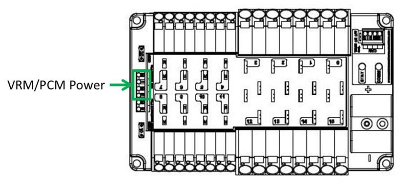
2021 FIRST® Robotics Competition

       chassis, the string extends across the gap and the resulting FRAME PERIMETER is a
       triangle with three sides.

R2. In the STARTING CONFIGURATION (the physical configuration in which a ROBOT starts a MATCH),
    no part of the ROBOT shall extend outside the vertical projection of the FRAME PERIMETER, with
    the exception of its BUMPERS and minor protrusions such as bolt heads, fastener ends, rivets, cable
    ties, etc.

       If a ROBOT is designed as intended and each side is pushed up against a vertical wall
       (in STARTING CONFIGURATION and with BUMPERS removed), only the FRAME
       PERIMETER (or minor protrusions) will be in contact with the wall.

       The allowance for minor protrusions in R2 is intended to allow protrusions that are both
       minor in extension from the FRAME PERIMETER and cross-sectional area.

       If a ROBOT uses interchangeable MECHANISMS per I3, Teams should be prepared to
       show compliance with R2 and R4 in all configurations.

R3. A ROBOT’S STARTING CONFIGURATION may not have a FRAME PERIMETER greater than 120
    in. (~304 cm) and may not be more than 45 in. (~114 cm) tall.

       Be sure to consider the size of the ROBOT on its cart to make sure it will fit through
       doors. Also consider the size of the ROBOT to ensure that it will fit into a shipping crate,
       vehicle, etc.

       Note that the BUMPER Rules contained in BUMPER Rules may impose additional
       restrictions on ROBOT design.

R4. ROBOTS may not extend more than 12 in. (~30 cm) beyond their FRAME PERIMETER (see Figure
    9-1)

                                 Figure 9-1 FRAME PERIMETER extension

       Expect to have to demonstrate a ROBOT’S ability to constrain itself per above during
       Inspection. Constraints may be implemented with either hardware or software.

                                                                              9 ROBOT Construction Rules
                                                                                                      V1
                                                                                               72 of 113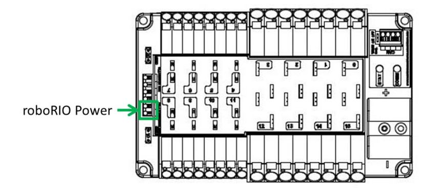
2021 FIRST® Robotics Competition

        See Game Rules: ROBOTS for height and extension restrictions for various areas of the
        FIELD.

R5. The ROBOT weight must not exceed 125 lbs. (~56 kg). When determining weight, the basic ROBOT
    structure and all elements of all additional MECHANISMS that might be used in a single configuration
    of the ROBOT shall be weighed together (see I3).

      For the purposes of determining compliance with the weight limitations, the following items are
      excluded:

          A. ROBOT BUMPERS
          B. ROBOT battery and its associated half of the Anderson cable quick connect/disconnect pair
             (including no more than 12 in. (~30 cm) of cable per leg, the associated cable lugs,
             connecting bolts, and insulation)
          C. tags used for location detection systems if provided by the event

9.3     ROBOT Safety & Damage Prevention
R6. Traction devices must not have surface features that could damage the ARENA (e.g. metal,
    sandpaper, hard plastic studs, cleats, hook-loop fasteners or similar attachments). Traction devices
    include all parts of the ROBOT that are designed to transmit any propulsive and/or braking forces
    between the ROBOT and FIELD carpet.

R7. Protrusions from the ROBOT and exposed surfaces on the ROBOT shall not pose hazards to the
    ARENA elements (including the POWER CELLS) or people.

R8. ROBOT parts shall not be made from hazardous materials, be unsafe, cause an unsafe condition, or
    interfere with the operation of other ROBOTS.

        Examples of items that will violate R8 include (but are not limited to):

            Shields, curtains, or any other devices or materials designed or used to obstruct or
            limit the vision of any DRIVERS and/or COACHES and/or interfere with their ability to
            safely control their ROBOT
            Speakers, sirens, air horns, or other audio devices that generate sound at a level
            sufficient to be a distraction
            Any devices or decorations specifically intended to jam or interfere with the remote
            sensing capabilities of another ROBOT, including vision systems, acoustic range
            finders, sonars, infrared proximity detectors, etc. (e.g. including imagery on your
            ROBOT that, to a reasonably astute observer, mimics the retro-reflective features of
            vision targets described in Vision Targets)
            Exposed lasers other than Class I.
            Flammable gasses
            Any device intended to produce flames or pyrotechnics
            Hydraulic fluids or hydraulic items
            Switches or contacts containing liquid mercury
            Circuitry used to create voltages in excess of 24 Volts
            Any ballast not secured sufficiently, including loose ballast e.g. sand, ball bearings,
            etc., such that it may become loose during a MATCH
            Exposed, untreated hazardous materials (e.g. lead weights) used on the ROBOT.
            These materials may be permitted if painted, encapsulated or otherwise sealed to
            prevent contact. These materials may not be machined in any way at an event.
            Tire sealant

                                                                               9 ROBOT Construction Rules
                                                                                                       V1
                                                                                                73 of 113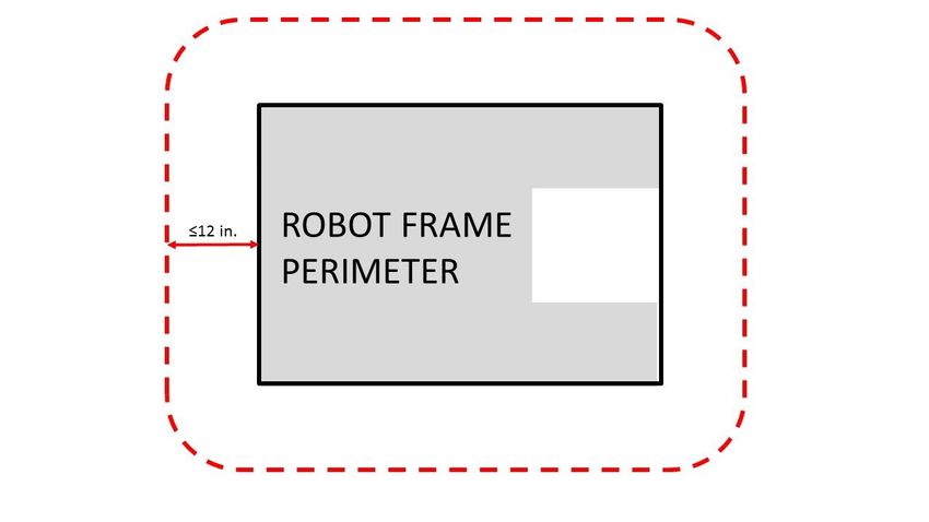
2021 FIRST® Robotics Competition

          High intensity light sources used on the ROBOT (e.g. super bright LED sources
          marketed as ‘military grade’ or ‘self-defense’) may only be illuminated for a brief time
          while targeting and may need to be shrouded to prevent any exposure to
          participants. Complaints about the use of such light sources will be followed by re-
          inspection and possible disablement of the device.
       Teams should provide MSD Sheets for any materials they use that might be considered
       questionable during ROBOT Inspection.

R9. ROBOTS must allow removal of game pieces from the ROBOT and the ROBOT from FIELD
    elements while DISABLED and powered off.

       ROBOTS will not be re-enabled after the MATCH, so teams must be sure that game
       pieces and ROBOTS can be quickly, simply, and safely removed.

       Teams are encouraged to consider rule C7 when developing their ROBOTS.

R10.   Lubricants may be used only to reduce friction within the ROBOT. Lubricants must not
   contaminate the FIELD or other ROBOTS.

9.4    Budget Constraints & Fabrication Schedule
R11.   This rule has been removed for the 2021 season.

R12.   No individual, non-KOP item or software used on the ROBOT shall have a Fair Market Value that
   exceeds $500 USD. The total cost of COMPONENTS purchased in bulk may exceed $500 USD as
   long as the cost of an individual COMPONENT does not exceed $500 USD.

       Teams should be ready to show inspectors documentation of Fair Market Value (FMV)
       for any COMPONENTS that appear to be in the range of the $500 USD limit.

       The Analog Devices ADIS16448 IMU MXP Breakout Board does not have a published
       FMV. This device is considered to comply with R12 regardless of its true FMV.

       The FMV of a COTS item is its price defined by a VENDOR for the part or an identical
       functional replacement. This price must be generally available to all FIRST Robotics
       Competition teams throughout the build and competition season (i.e. short-term sale
       prices or coupons do not reflect FMV), however teams are only expected to make a good
       faith effort at determining the item price and are not expected to monitor prices of
       ROBOT items throughout the season. The FMV is the cost of the item itself and does not
       include any duties, taxes, tariffs, shipping, or other costs that may vary by locality.

       The FMV of COTS software is the price, set by the VENDOR, to license the software (or
       component of the software) that runs on the ROBOT for the period from Kickoff to the
       end of the FIRST Championship. The FMV of software licensed free-of-cost, including
       through the Virtual KOP, for use on the ROBOT is $0.

       The FMV of FABRICATED parts is the value of the material and/or labor, except for labor
       provided by team members (including sponsor employees who are members of the
       team), members of other teams, and/or event provided Machine Shops. Material costs
       are accounted for as the cost of any purchasable quantity that can be used to make the
       individual part (i.e. the purchasable raw material is larger than the FABRICATED part).

       Example 1: A team orders a custom bracket made by a company to the team’s
       specification. The company’s material cost and normally charged labor rate apply.

                                                                             9 ROBOT Construction Rules
                                                                                                     V1
                                                                                              74 of 113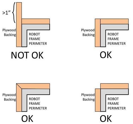
2021 FIRST® Robotics Competition

       Example 2: A team receives a donated sensor. The company would normally sell this
       item for $450 USD, which is therefore its FMV.

       Example 3: A team purchases titanium tube stock for $400 USD and has it machined by
       a local machine shop. The machine shop is not considered a team Sponsor but donates
       two (2) hours of expended labor anyway. The team must include the estimated normal
       cost of the labor as if it were paid to the machine shop and add it to the $400 USD.

       Example 4: A team purchases titanium tube stock for $400 USD and has it machined by
       a local machine shop that is a recognized Sponsor of the team. If the machinists are
       considered members of the team, their labor costs do not apply. The total applicable cost
       for the part would be $400 USD.

       It is in the best interests of the teams and FIRST to form relationships with as many
       organizations as possible. Teams are encouraged to be expansive in recruiting and
       including organizations in their team, as that exposes more people and organizations to
       FIRST. Recognizing supporting companies as Sponsors of, and members in, the team is
       encouraged, even if the involvement of the Sponsor is solely through the donation of
       fabrication labor.

       Example 5: A team purchases titanium tube stock for $400 USD and has it machined by
       another team. The total applicable cost for the part would be $400 USD.

       Example 6: A team purchases a widget at a garage sale or online auction for $300, but
       it’s available for sale from a VENDOR for $700. The FMV is $700.

       If a COTS item is part of a modular system that can be assembled in several possible
       configurations, then each individual module must fit within the price constraints defined in
       R12.

       If the modules are designed to assemble into a single configuration, and the assembly is
       functional in only that configuration, then the total cost of the complete assembly
       including all modules must fit within the price constraints defined in R12.

       In summary, if a VENDOR sells a system or a kit, a team must use the entire system/kit
       FMVand not the value of its COMPONENT pieces.

       Example 1: VENDOR A sells a gearbox that can be used with a number of different gear
       sets, and can mate with two different motors they sell. A team purchases the gearbox, a
       gear set, and a motor, then assembles them together. Each part is treated separately for
       the purpose of determining FMV, since the purchased pieces can each be used in
       various configurations.

       Example 2: VENDOR B sells a robotic arm assembly that the team wants to use.
       However, it costs $700 USD, so they cannot use it. The VENDOR sells the “hand”,
       “wrist”, and “arm” as separate assemblies, for $200 USD each. A team wishes to
       purchase the three items separately, then reassemble them. This would not be legal, as
       they are really buying and using the entire assembly, which has a FMV of $700 USD.

       Example 3: VENDOR C sells a set of wheels or wheel modules that are often used in
       groups of four. The wheels or modules can be used in other quantities or configurations.
       A team purchases four and uses them in the most common configuration. Each part is
       treated separately for the purpose of determining FMV, since the purchased pieces can
       be used in various configurations.

R13.   This rule has been removed for the 2021 season.

                                                                             9 ROBOT Construction Rules
                                                                                                     V1
                                                                                              75 of 113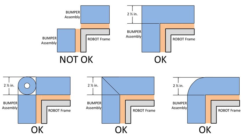
2021 FIRST® Robotics Competition

R14.    This rule has been removed for the 2021 season.

R15.    This rule has been removed for the 2021 season.

R16.    During an event a team is attending (regardless of whether the team is physically at the event
   location), the team may neither work on nor practice with their ROBOT or ROBOT elements outside
   of the hours that pits are open, with the following exceptions:

          A. OPERATOR CONSOLE,
          B. BUMPERS (a protective assembly designed to attach to the exterior of the ROBOT and
             constructed as specified in BUMPER Rules),
          C. battery assemblies as described in R5-B,
          D. FABRICATED ITEMS consisting of one COTS electrical device (e.g. a motor or motor
             controller) and attached COMPONENTS associated with any of the following modifications:
             i. wires modified to facilitate connection to a ROBOT (including removal of existing
                  connectors)
             ii. connectors and any materials to secure and insulate those connectors added (Note:
                  passive PCBs such as those used to adapt motor terminals to connectors are
                  considered connectors)
             iii. motor shafts modified and/or gears, pulleys, or sprockets added
             iv. motors modified with a filtering capacitor as described in the Blue Box below R56
          E. COTS items with any of the following modifications:
             i. Non-functional decoration or labeling
             ii. Assembly of COTS items per manufacturer specs, unless the result constitutes a
                  MAJOR MECHANISM as defined in I1
          F. Software development
          G. Batteries may be charged during the designated Load-in time

        For the purposes of this rule, official events begin at the start of the first designated Load-
        in period, according to the Public Schedule. If the Public Schedule is not available or the
        Public Schedule does not include a Load-in period, the event begins at 6 AM local time.
        Examples of activity prohibited by R16 include:
            Working on the ROBOT at the team’s shop after Load-in for the event has begun
            Working on ROBOT parts at night at the team’s hotel.
        Note that E8 and E20 impose additional restrictions on work done on the ROBOT or
        ROBOT materials while attending an event.
        One purpose of R16 is to increase equity between teams with significant travel to an
        event and those nearby (close teams would otherwise have an advantage by being able
        to work on their ROBOT, in their shop, until it’s time to go to the event).

9.5     BUMPER Rules
A BUMPER is a required assembly which attaches to the ROBOT frame. BUMPERS protect ROBOTS
from damaging/being damaged by other ROBOTS and FIELD elements. Criteria used in writing these
rules includes the following:

    •       Minimize variety of BUMPERS so teams can expect consistency
    •       Minimize the amount of design challenge in creating BUMPERS
    •       Minimize cost of BUMPER materials
    •       Maximize use of relatively ubiquitous materials

                                                                                9 ROBOT Construction Rules
                                                                                                        V1
                                                                                                 76 of 113
2021 FIRST® Robotics Competition
R17. ROBOTS are required to use BUMPERS to protect all outside corners of the FRAME
PERIMETER. For adequate protection, at least 6 in. (~16 cm) of BUMPER must be placed on each
side of each outside corner (see Figure 9-2 BUMPER corner examples) and must extend to within ¼
in. (~6 mm) of the FRAME PERIMETER corner. If a FRAME PERIMETER side is shorter than 12 in.
(~31 cm), that entire side must be protected by BUMPER (see Figure 9-3). A round or circular
FRAME PERIMETER, or segment of the FRAME PERIMETER, is considered to have an infinite
number of corners, therefore the entire frame or frame segment must be completely protected by
BUMPER(S).
The dimension defined in R17 is measured along the FRAME PERIMETER. The portion
of the BUMPER that extends beyond the corner of the FRAME PERIMETER is not
included in the 6 in. (~16 cm) requirement. See Figure 9-2.
Figure 9-2 BUMPER corner examples
9 ROBOT Construction Rules
V1
77 of 1132021 FIRST® Robotics Competition
Figure 9-3 BUMPER around full side/corner
R18. Except as allowed per G16, BUMPERS must be located entirely within the BUMPER ZONE,
which is the volume contained between the floor and a virtual horizontal plane 7½ in. (~19 cm) above
the floor in reference to the ROBOT standing normally on a flat floor. BUMPERS do not have to be
parallel to the floor.
This measurement is intended to be made as if the ROBOT is resting on a flat floor
(without changing the ROBOT configuration), not relative to the height of the ROBOT
from the FIELD carpet. Examples include:
Example 1: A ROBOT that is at an angle while navigating the FIELD has its BUMPERS
outside the BUMPER ZONE. If this ROBOT were virtually transposed onto a flat floor,
and its BUMPERS are in the BUMPER ZONE, it meets the requirements of R18.
Example 2: A ROBOT deploys a MECHANISM which lifts the BUMPERS outside the
BUMPER ZONE (when virtually transposed onto a flat floor). This violates R18.
R19. BUMPERS must not be articulated (relative to the FRAME PERIMETER).
R20. BUMPERS (the entire BUMPER, not just the cover) must be designed for quick and easy
installation and removal to facilitate Inspection and weighing.
As a guideline, BUMPERS should be able to be installed or removed by two (2) people in
fewer than five (5) minutes.
R21. Each ROBOT must be able to display primarily Red or Blue BUMPERS to MATCH their
ALLIANCE color, as assigned in the MATCH schedule distributed at the event (as described in
MATCH Schedules). A BUMPER is considered primarily Red or Blue if all displayed BUMPER
surfaces other than corners (i.e. everywhere the BUMPER is backed by the FRAME PERIMETER)
displays the appropriate color. Any visible fabric other than the primary color must be a solid color.
See Figure 9-4. BUMPER Markings visible when installed on the ROBOT, other than the following,
are prohibited:
9 ROBOT Construction Rules
V1
78 of 1132021 FIRST® Robotics Competition
A. those required per R22,
B. hook-and-loop fastener or snap fasteners backed by the hard parts of the BUMPER, and
C. solid white FIRST logos between 4¾ in. (~12 cm) and 5¼ in. wide (~13 cm) (i.e.
comparable to those available in the 2021 Virtual Kit).
The FRAME PERIMETER facing surfaces and short perpendicular “ends” of BUMPERS
are not “displayed” and thus R21 does not apply.
Figure 9-4 BUMPER color example
R22. Team numbers must be displayed and positioned on the BUMPERS such that an observer
walking around the perimeter of the ROBOT can unambiguously tell the team’s number from any
point of view and meet the following additional criteria:
A. consist of only Arabic numerals at least 4 in. (~11 cm) high, at least ½ in. (~13 mm) in
stroke width, and be either white in color or outlined in white with a minimum 1/16 in. (~2
mm) outline
The ½ in. (~13 mm) stroke width requirement applies to the majority of the stroke. Font
elements less than ½ in. (~13 mm) such as serifs, rounded edges, small hairlines or
gaps, etc. are permitted as long as the majority of the stroke meets the sizing
requirement and the numbers are unambiguous.
B. must not wrap around sharp corners (less than 160 degrees) of the FRAME PERIMETER
C. may not substitute logos or icons for numerals
There is no prohibition against splitting team numbers onto different sections of
BUMPER. The intent is that the team’s number is clearly visible and unambiguous so that
Judges, REFEREES, Announcers, and other teams can easily identify competing
ROBOTS.
9 ROBOT Construction Rules
V1
79 of 1132021 FIRST® Robotics Competition
This marking is intended to display the team number only, not to intentionally change the
surface characteristics of the BUMPER. Excessive material usage as part of any team
number marking will invite close scrutiny.
R23. Each set of BUMPERS (including any fasteners and/or structures that attach them to the
ROBOT) must weigh no more than 15 lbs. (~6 kg).
If a multi-part attachment system is utilized (e.g. interlocking brackets on the ROBOT and
the BUMPER), then the elements permanently attached to the ROBOT will be considered
part of the ROBOT, and the elements attached to the BUMPERS will be considered part
of the BUMPER. Each element must satisfy all applicable rules for the relevant system.
R24. BUMPERS must be constructed as follows (see Figure 9-7):
A. be backed by ¾ in. (nominal) thick (~19mm) by 5 in. ± ½ in. (~127 mm ± 12.7 mm) tall
plywood, Oriented Strand Board (OSB) or solid wood (with the exception of balsa). Small
clearance pockets and/or access holes in the wood backing are permitted, as long as they
do not significantly affect the structural integrity of the BUMPER.
¾ in. Plywood and OSB refer to items sold by VENDORS as that material and thickness,
teams may not fabricate their own plywood or OSB. Other engineered woods such as
Fiberboard or Particle Board are not likely to survive the rigors of FIRST Robotics
Competition gameplay and thus not permitted in R24-A.
Note: ¾ in. plywood is now often marked according to the actual dimension (²³⁄₃₂ in.) not
the nominal size. Plywood sold as ²³⁄₃₂ in. meets the requirements of R24-A.
B. hard BUMPER parts allowed per R24-A, -E, -F, and -G must not extend more than 1 in.
(~25 mm) beyond the FRAME PERIMETER (measured as shown in Figure 9-5).
Figure 9-5 Hard parts of BUMPER corners
9 ROBOT Construction Rules
V1
80 of 1132021 FIRST® Robotics Competition
C. use a stacked pair of approximately 2½ in. (nominal, ~63mm) round, petal, or hex “pool
noodles” (solid or hollow) as the BUMPER cushion material (see Figure 9-7). All pool
noodles used in a BUMPER set (e.g. Red set of BUMPERS) may not be modified (with the
exception of cutting to length or cutting to facilitate mating pool noodles at the corners as
required by R25) or deformed and must be the same diameter, cross-section, and density
(e.g. all round hollow or all hex solid). Cushion material may extend up to 2½ in. (~63 mm)
beyond the end of the plywood (see Figure 9-8). To assist in applying the fabric covering,
soft fasteners may be used to attach the pool noodles to the wood backing, so long as the
cross section in Figure 9-7 is not significantly altered (e.g. tape compressing the pool
noodles).
All pool noodles used on a ROBOT must be the same in order to maintain the desired
interaction between ROBOTS in the cases of BUMPER-to-BUMPER contact. BUMPERS
containing pool noodles of vastly different construction may cause a “ramp” effect when
interacting with other BUMPERS.
Minor noodle compression as a result of smoothing BUMPER fabric or rounding a
FRAME PERIMETER corner is not considered deformed. Any compression beyond that,
e.g. for the purposes of flattening the noodle, is deformation and a violation of R24-C.
D. be covered with a rugged, smooth cloth. (multiple layers of cloth and seams are permitted if
needed to accommodate R21 and/or R22, provided the cross section in Figure 9-7 is not
significantly altered).
Silk and bedding are not considered rugged cloths, however 1000D Cordura is. Tape
(e.g. gaffer’s tape) matching the BUMPER color is allowed to patch small holes on a
temporary basis.
It is expected that there may be multiple layers of cloth as fabric is folded to
accommodate the corners and seams of BUMPERS.
The cloth must completely enclose all exterior surfaces of the wood and pool noodle
material when the BUMPER is installed on the ROBOT. The fabric covering the BUMPERS
must be solid in color.
BUMPER corners and “ends”, shown in Figure 9-4, must be solid in color, but do not
need to be the same color as the rest of the BUMPER, as described in R21.
E. optionally use metal angle, as shown in Figure 9-7 or other fasteners (e.g. staples, screws,
adhesives, etc.) to clamp cloth.
F. optionally use metal brackets (i.e. angle or sheet metal) or other fasteners (e.g. staples,
screws, adhesives, etc.) to attach BUMPER segments to each other (see Figure 9-6).
Figure 9-6 Hard parts of BUMPER corners
9 ROBOT Construction Rules
V1
81 of 1132021 FIRST® Robotics Competition
G. must attach to the FRAME PERIMETER of the ROBOT with a rigid fastening system to
form a tight, robust connection to the main structure/frame (e.g. not attached with hook-
and-loop, tape, or tie-wraps). The attachment system must be designed to withstand
vigorous game play. All removable fasteners (e.g. bolts, locking pins, pip-pins, etc.) will be
considered part of the BUMPERS.
Figure 9-7 BUMPER vertical cross section
R25. Corner joints between BUMPERS must be filled with pool noodle material. Examples of
implementation are shown in Figure 9-8.
Figure 9-8 Soft parts of BUMPER corners
9 ROBOT Construction Rules
V1
82 of 1132021 FIRST® Robotics Competition
R26. BUMPERS must be supported by the structure/frame of the ROBOT (see Figure 9-9). To be
considered supported, a minimum of ½ in. (~13 mm) at each end of each BUMPER wood segment
must be backed by the FRAME PERIMETER (≤¼ in. gap, ~6mm). “Ends” exclude hard BUMPER
parts which extend past the FRAME PERIMETER permitted by R24-B. Additionally, any gap between
the backing material and the frame:
A. must not be greater than ¼ in. (~6 mm) deep, or
B. not more than 8 in. (~20 cm) wide
Figure 9-9 BUMPER support examples
The intent of this rule is to make sure the BUMPER wood is properly supported to
minimize the likelihood of breakage on impact. Flexible ROBOT elements, such as thin
plastic, do not accomplish this intent and are not considered “structure/frame” of the
ROBOT.
9 ROBOT Construction Rules
V1
83 of 1132021 FIRST® Robotics Competition
9.6 Motors & Actuators
R27. The only motors and actuators permitted on 2021 ROBOTS include the following (in any
quantity):
Table 9-1 Motor allowances
Motor Name Part Numbers Available
AndyMark 9015 am-0912 AndyMark 9015
AndyMark NeveRest am-3104
AndyMark PG am-2161 (alt. PN am- am-2194 (alt. PN am-2766)
2765)
AndyMark RedLine Motor am-3775 am-3775a
AndyMark Snow Blower Motor am-2235 am-2235a
Banebots am-3830 M5 – RS550-12
M7-RS775-18 RS550VC-7527
RS775WC-8514 RS550
CIM FR801-001 PM25R-45F-1004
M4-R0062-12 PM25R-45F-1003
AM802-001A PMR25R-45F-1003
217-2000 PMR25R-44F-1005
PM25R-44F-1005 am-0255
CTR Electronics/VEX Robotics 217-6515 19-708850
Falcon 500 am-6515 am-6515_Short
Current/former KOP Automotive Denso AE235100-0160 Denso 262100-3040
motors Denso 5-163800-RC1 Bosch 6 004 RA3 194-06
Denso 262100-3030 Johnson Electric JE-PLG-149
Nidec Dynamo BLDC Motor am-3740 DM3012-1063
Playing with Fusion Venom BDC-10001
REV Robotics HD Hex Motor REV-41-1291
REV Robotics NEO Brushless REV-21-1650
REV Robotics NEO 550 REV-21-1651
VEX BAG 217-3351
VEX Mini-CIM 217-3371
West Coast Products RS775 Pro 217-4347
Electrical solenoid actuators, no greater than 1 in. (nominal) stroke and rated electrical
input power no greater than 10 watts (W) continuous duty at 12 volts (VDC)
Fans, no greater than 120mm (nominal) size and rated electrical input power no greater
than 10 watts (W) continuous duty at 12 volts (VDC)
Hard drive motors part of a legal COTS computing device
Factory installed vibration and autofocus motors resident in COTS computing devices
(e.g. rumble motor in a smartphone).
PWM COTS servos with a retail cost < $75.
Motors integral to a COTS sensor (e.g. LIDAR, scanning sonar, etc.), provided the
device is not modified except to facilitate mounting
One (1) compressor compliant with R79 and used to compress air for the ROBOT’S
pneumatic system
For servos, note that the roboRIO is limited to a max current output of 2.2A on the 6V rail
(12.4W of electrical input power). Teams should make sure that their total servo power
usage remains below this limit at all times.
Given the extensive amount of motors allowed on the ROBOT, teams are encouraged to
consider the total power available from the ROBOT battery during the design and build of
9 ROBOT Construction Rules
V1
84 of 1132021 FIRST® Robotics Competition
the ROBOT. Drawing large amounts of current from many motors at the same time could
lead to drops in ROBOT battery voltage that may result in tripping the main breaker or
trigger the brownout protection of the roboRIO. For more information about the roboRIO
brownout protection and measuring current draw using the PDP, see roboRIO Brownout
and Understanding Current Draw.
AndyMark PG Gearmotors are sold with labeling based on the entire assembly.
Assemblies labeled am-3651 through am-3656 contain legal motors specified in the table
above. These motors may be used with or without the provided gearbox.
R28. The integral mechanical and electrical system of any motor must not be modified. Motors, servos,
and electric solenoids used on the ROBOT shall not be modified in any way, except as follows:
A. The mounting brackets and/or output shaft/interface may be modified to facilitate the
physical connection of the motor to the ROBOT and actuated part.
B. The electrical leads may be trimmed to length as necessary and connectors or splices to
additional wiring may be added.
C. The locking pins on the window motors (P/N: 262100-3030 and 262100-3040) may be
removed.
D. The connector housings on KOP Automotive motors listed in Table 9-1 may be modified to
facilitate lead connections.
E. Servos may be modified as specified by the manufacturer (e.g. re-programming or
modification for continuous rotation).
F. The wiring harness of the Nidec Dynamo BLDC Motor may be modified as documented by
FIRST in the “Nidec Dynamo BLDC Motor with Controller” article.
G. Minimal labeling applied to indicate device purpose, connectivity, functional performance,
etc.
H. Any number of #10-32 plug screws may be removed from the Falcon 500.
I. Insulation may be applied to electrical terminals.
The intent of this rule is to allow teams to modify mounting tabs and the like, not to gain a
weight reduction by potentially compromising the structural integrity of any motor.
R29. With the exception of servos, fans, or motors integral to sensors of COTS computing devices
permitted in R27, each actuator must be controlled by a power regulating device. The only power
regulating devices for actuators permitted on the ROBOT include:
A. Motor Controllers
i. DMC 60/DMC 60c Motor Controller (P/N: 410-334-1, 410-334-2)
ii. Jaguar Motor Controller (P/N: MDL-BDC, MDL-BDC24, and 217-3367) connected to
PWM only
iii. Nidec Dynamo BLDC Motor with Controller to control integral actuator only (P/N 840205-
000, am-3740)
iv. SD540 Motor Controller (P/N: SD540x1, SD540x2, SD540x4, SD540Bx1, SD540Bx2,
SD540Bx4, SD540C)
v. Spark Motor Controller (P/N: REV-11-1200)
vi. Spark MAX Motor Controller (P/N: REV-11-2158)
vii. Talon FX Motor Controller (P/N: 217-6515, 19-708850, am-6515, am-6515_Short) for
controlling integral Falcon 500 only
viii. Talon Motor Controller (P/N: CTRE_Talon, CTRE_Talon_SR, and am-2195)
ix. Talon SRX Motor Controller (P/N: 217-8080, am-2854, 14-838288)
x. Venom Motor with Controller (P/N: BDC-10001) for controlling integral motor only
9 ROBOT Construction Rules
V1
85 of 1132021 FIRST® Robotics Competition
xi. Victor 884 Motor Controller (P/N: VICTOR-884-12/12)
xii. Victor 888 Motor Controller (P/N: 217-2769)
xiii. Victor SP Motor Controller (P/N: 217-9090, am-2855, 14-868380)
xiv. Victor SPX Motor Controller (P/N: 217-9191, 17-868388, am-3748)
B. Relay Modules
i. Spike H-Bridge Relay (P/N: 217-0220 and SPIKE-RELAY-H)
ii. Automation Direct Relay (P/N: AD-SSR6M12-DC-200D, AD-SSRM6M25-DC-200D, AD-
SSR6M40-DC-200D)
C. Pneumatics controllers
i. Pneumatics Control Module (P/N: am-2858, 217-4243)
Note: The Automation Direct Relays are single directional. Per R30 they may not be
wired together in an attempt to provide bi-directional control.
R30. Each power regulating device may control electrical loads per Table 9-2. Unless otherwise noted,
each power regulating device shall control one and only one electrical load.
Table 9-2 Power regulating device allotments
Motor Pneumatics
Electrical Load Relay Module
Controller Controller
AndyMark RedLine Motor
Banebots
CIM
REV Robotics NEO Brushless Yes No No
REV Robotics NEO 550
VEX Mini-CIM
WCP RS775 Pro
Yes
AndyMark 9015
(up to 2
VEXpro BAG No No
per
controller)
AndyMark PG
Yes
KOP Automotive Motors
(up to 2
NeverRest Yes No
per
Snow Blower Motor
controller)
CTR Electronics/VEX Falcon 500 Yes
Nidec Dynamo BLDC Motor w/ (integrated
No No
Controller controller
Playing With Fusion Venom only)
Compressor No Yes Yes
Yes
Pneumatic Solenoid Valves No Yes1
(1 per channel)
Yes
Electric Solenoids Yes1 Yes1
(1 per channel)
Yes
CUSTOM CIRCUITS2 Yes1 Yes1
(1 per channel)
9 ROBOT Construction Rules
V1
86 of 1132021 FIRST® Robotics Competition
1Multiple low-load, pneumatic solenoid valves (relay only), electric solenoids or CUSTOM CIRCUITS may
be connected to a single relay module or motor controller. This would allow one (1) relay module or motor
controller to drive multiple pneumatic actions or multiple CUSTOM CIRCUITS. No other electrical load
can be connected to a relay module used in this manner.
2A CUSTOM CIRCUIT is any electrical COMPONENT of the ROBOT other than motors, pneumatic
solenoids, roboRIO, PDP, PCM, VRM, RSL, 120A breaker, motor controllers, relay modules (per R29-B),
wireless bridge, electrical solenoid actuators, or batteries.
R31. Servos must be connected to, and only to, one of the following:
A. PWM PORTS on the roboRIO
B. PWM PORTS on a WCP Spartan Sensor Board (P/N: WCP-0045)
C. REV Robotics Servo Power Module (P/N: REV-11-1144)
9.7 Power Distribution
In order to maintain safety, the rules in this section apply at all times while at the event, not just while the
ROBOT is on the FIELD for MATCHES.
R32. The only legal source of electrical energy for the ROBOT during the competition, the ROBOT
battery, must be one and only one non-spillable sealed lead acid (SLA) battery with the following
specifications:
A. Nominal voltage: 12V
B. Nominal capacity at 20-hour discharge rate: minimum 17Ah, maximum 18.2Ah
C. Shape: Rectangular
D. Nominal Dimensions:7.1 in. x 3 in. x 6.6 in., +/- .1 in. for each dimension (~ 180 mm x
76mm x 168 mm, +/- 2.5 mm for each dimension)
E. Nominal weight: 11lbs. to 14.5 lbs. (~5 kg. to 6.5 kg.)
F. Terminals: Nut and bolt style
Examples of batteries which meet these criteria include:
Enersys (P/N: NP18-12, NP18-12B, NP18-12BFR)
MK Battery (P/N: ES17-12)
Battery Mart (P/N: SLA-12V18)
Sigma (P/N: SP12-18)
Universal Battery (P/N: UB12180)
Power Patrol (P/N: SLA1116)
Werker Battery (P/N: WKA12-18NB)
Power Sonic (P/N: PS-12180NB)
Yuasa (P/N: NP18-12B)
Panasonic (P/N: LC-RD-1217)
Interstate Batteries (P/N: BSL1116)
Duracell Ultra Battery (P/N: DURA12-18NB)
Teams should be aware that they may be asked to provide documentation of the
specifications of any battery not listed above.
Batteries should be charged in accordance with manufacturer’s specification. (Please see
the FIRST Safety Manual for additional information.)
R33. COTS USB battery packs with a capacity of 100Wh or less (20000mAh at 5V) and 2.5 Amp max
output per port, or batteries integral to and part of a COTS computing device or self-contained
9 ROBOT Construction Rules
V1
87 of 1132021 FIRST® Robotics Competition
camera (e.g. laptop batteries, GoPro style camera, etc.) may be used to power COTS computing
devices and any peripheral COTS input or output devices connected to the COTS computing device
provided they are:
A. securely fastened to the ROBOT,
B. connected only using unmodified COTS cables, and
C. charged according to manufacturer recommendations.
R34. Any battery charger used to charge a ROBOT battery must have the corresponding Anderson SB
connector installed.
R35. Any battery charger used to charge a ROBOT battery may not be used such that it exceeds 6-
Amp peak charge current.
R36. No batteries other than those allowed per R32 and R33 are allowed on the ROBOT, whether or
not they are being used to supply power.
For example, teams may not use additional batteries as extra weight on their ROBOTS.
R37. The ROBOT battery must be secured such that it will not dislodge during vigorous ROBOT
interaction including if the ROBOT is turned over or placed in any arbitrary orientation.
R38. Each electrical terminal on the ROBOT battery, main breaker, and their connections (lugs,
stripped wire ends, etc.) to the wire must be fully insulated at all times.
R39. Non-electrical sources of energy used by the ROBOT, (i.e., stored at the start of a MATCH), shall
come only from the following sources:
A. compressed air stored in the pneumatic system that has been charged in compliance with
R79 and R80,
B. a change in the altitude of the ROBOT center of gravity,
C. storage achieved by deformation of ROBOT parts,
D. closed-loop COTS pneumatic (gas) shocks, and
E. air-filled (pneumatic) wheels.
9 ROBOT Construction Rules
V1
88 of 1132021 FIRST® Robotics Competition
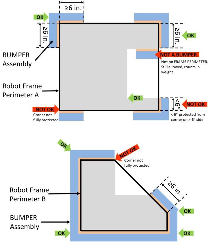
R40. The one (1) ROBOT battery, a single pair of Anderson Power Products (or APP) 2-pole SB type
connectors, the one (1) main 120-amp (120A) surface mount circuit breaker (Cooper Bussman P/N:
CB185-120, CB185F-120, CB285-120), and the one (1) CTR Electronics Power Distribution Panel
(PDP, P/N: am-2856, 217-4244, 14-806880) shall be connected with 6 AWG (7 SWG or 16 mm2)
copper wire or larger, with no additional devices or modifications, as shown in Figure 9-10.
Figure 9-10 Electrical connection diagram
“SB type” refers to SB type only (e.g. SB-50, SB-120, etc.), not SBS or any other part
type beginning with SB. All batteries supplied by FIRST (such as Spare Parts and
international batteries) will have a Red or Pink SB50 connector installed which may not
be removed.
The pink connectors included in the 2020 KOP mate with the Red SB50 connector.
R41. All circuits, with the exceptions of those listed in R46 and R48, must connect to, and have power
sourced solely by, a single protected 12VDC WAGO connector pair (i.e. the Load Terminals, as
shown in Figure 9-10) of the one (1) CTR Electronics Power Distribution Panel, not the M6 cap
screws.
R42. All wiring and electrical devices, including all Control System COMPONENTS, shall be electrically
isolated from the ROBOT frame. The ROBOT frame must not be used to carry electrical current.
R42 is checked by observing a >3kΩ resistance between either the (+) or (-) post within
the APP connector that is attached to the PDP and any point on the ROBOT.
All legal motor controllers with metal cases are electrically isolated. They may be
mounted directly to ROBOT frame COMPONENTS.
9 ROBOT Construction Rules
V1
89 of 1132021 FIRST® Robotics Competition
Note that some cameras, decorative lights and sensors (e.g. some encoders, some IR
sensors, etc.) have grounded enclosures or are manufactured with conductive plastics.
These devices must be electrically isolated from the ROBOT frame to ensure compliance
with R42.
R43. The 120A circuit breaker must be quickly and safely accessible from the exterior of the ROBOT.
This is the only 120A circuit breaker allowed on the ROBOT.
Examples considered not “quickly and safely accessible” include breakers covered by an
access panel or door, or mounted on, underneath or immediately adjacent to moving
COMPONENTS.
It is strongly recommended that the 120A circuit breaker location be clearly and obviously
labeled so it can be easily found by FIELD STAFF during a MATCH.
R44. The PDP, associated wiring, and all circuit breakers must be visible for Inspection.
R45. Any active electrical item that is not an actuator (specified in R27) or core Control System item
(specified in R66) is considered a CUSTOM CIRCUIT. CUSTOM CIRCUITS shall not produce
voltages exceeding 24V.
R46. The roboRIO power input must be connected to the dedicated supply terminals on the PDP
shown in Figure 9-11. No other electrical load shall be connected to these terminals.
Figure 9-11 roboRIO power source
R47. The Wireless Bridge (Radio) power must be supplied directly by the 12V 2A output of a CTR
Electronics Voltage Regulator Module (VRM) (P/N: am-2857, 217-4245) and must be the only load
connected to those terminals.
Figure 9-12 Radio power source
Note that this wiring is different from the wiring for the radio used in 2015, but is identical
to the wiring from 2016-2020. When using a 2015 VRM with the OM5P-AN or OM5P-AC
9 ROBOT Construction Rules
V1
90 of 1132021 FIRST® Robotics Competition
radio, the radio should be connected as described above, not to the terminals labeled
“Radio”.
Note that this prohibits using any active POE Injector device to power the radio but does
not prohibit using any PASSIVE CONDUCTORS to inject the VRM power into an
Ethernet cable plugged into the radio port labeled “18-24v POE”.
R48. The VRM supplying power to the Wireless Bridge per R47 must be connected to the designated
supply terminals at the end of the PDP, and not the main WAGO connectors along the sides of the
PDP as shown in Figure 9-13. With the exception of a single CTR Electronics Pneumatics Control
Module (PCM, P/N: am-2858), no other electrical load shall be connected to these PDP terminals.
Figure 9-13 VRM and PCM power source
Please reference How to Wire an FRC Robot for Wireless Bridge wiring information.
R49. Only one wire shall be connected to each WAGO connector on the PDP.
If multi-point distribution of circuit power is needed (e.g. to provide power to multiple
PCMs and/or VRMs from one 20A circuit), then all incoming wires may be appropriately
spliced into the main lead (e.g. using an insulated terminal block, crimped splice or
soldered wire splice), and the single main lead inserted into the WAGO connector to
power the circuit.
R50. The only circuit breakers permitted for use in the PDP are:
A. Snap Action VB3-A Series, terminal style F57
B. Snap Action MX5-A or MX5-L Series, 40A rating or lower
R51. The fuses in the PDP shall only be replaced with functionally identical fuses (mini automotive
blade fuses with values matching those printed on the PDP).
Note that these fuses must be pressed very firmly to seat properly. Improper seating can
cause component reboots during impacts.
9 ROBOT Construction Rules
V1
91 of 1132021 FIRST® Robotics Competition
R52. Each branch circuit must be protected by one and only one circuit breaker on the PDP per Table
9-3. No other electrical load can be connected to the breaker supplying this circuit.
Table 9-3 Branch circuit protection requirements
Circuit Breaker Quantity Allowed
Branch Circuit Value Per Breaker
Motor Controller Up to 40A 1
CUSTOM CIRCUIT Up to 40A 1
Automation Direct Relay 40A (*6M40*) Up to 40A 1
Fans permitted per Table 9-1 and not Up to 20A No limit
already part of COTS computing devices
Spike Relay Module Up to 20A 1
Automation Direct Relay 25A (*6M25*) Up to 20A 1
PCM – with compressor 20A 1
Additional VRM (non-radio)/Additional 20A 3 total
PCM (non-compressor)
Automation Direct Relay 12A (*6M12*) Up to 10A 1
R52 does not prohibit the use of smaller value breakers in the PDP or any fuses or
breakers within CUSTOM CIRCUITS for additional protection.
R53. All circuits shall be wired with appropriately sized insulated copper wire (SIGNAL LEVEL cables
don’t have to be copper):
Table 9-4 Breaker and wire sizing
Application Minimum Wire Size
31 – 40A protected circuit 12 AWG
(13 SWG or 4 mm2)
21 – 30A protected circuit 14 AWG
(16 SWG or 2.5 mm2)
6 – 20A protected circuit 18 AWG
Between the PDP dedicated terminals and the VRM or PCM (19 SWG or 1 mm2)
Compressor outputs from the PCM
Between the PDP and the roboRIO 22 AWG
≤5A protected circuit (22 SWG or 0.5 mm2)
VRM 2A circuits 24 AWG
(24 SWG or .25mm2)
roboRIO PWM port outputs 26 AWG
(27 SWG or 0.14 mm2)
SIGNAL LEVEL circuits (i.e. circuits which draw ≤1A 28 AWG
continuous and have a source incapable of delivering >1A, (29 SWG or .08 mm2)
including but not limited to roboRIO non-PWM outputs,
CAN signals, PCM Solenoid outputs, VRM 500mA outputs
and Arduino outputs)
9 ROBOT Construction Rules
V1
92 of 1132021 FIRST® Robotics Competition
Wires that are recommended by the device manufacturer or originally attached to legal devices are
considered part of the device and by default legal. Such wires are exempt from R53.
In order to show compliance with these rules, teams should use wire with clearly labeled
sizes if possible. If unlabeled wiring is used, teams should be prepared to demonstrate
that the wire used meets the requirements of R53 (e.g. wire samples and evidence that
they are the required size).
R54. Branch circuits may include intermediate elements such as COTS connectors, splices, COTS
flexible/rolling/sliding contacts, and COTS slip rings, as long as the entire electrical pathway is via
appropriately gauged/rated elements.
Slip rings containing mercury are prohibited per R8.
R55. All non-SIGNAL LEVEL wiring with a constant polarity (i.e., except for outputs of relay modules,
motor controllers, or sensors) shall be color-coded along their entire length from the manufacturer as
follows:
A. Red, yellow, white, brown, or black-with-stripe on the positive (e.g. +24VDC, +12VDC,
+5VDC, etc.) connections.
B. Black or blue for the common or negative side (-) of the connections.
Exceptions to this rule include:
C. Wires that are originally attached to legal devices and any extensions to these wires using
the same color as the manufacturer.
D. Ethernet cable used in POE cables.
R56. CUSTOM CIRCUITS shall not directly alter the power pathways between the ROBOT battery,
PDP, motor controllers, relays (per R29-B), motors and actuators (per R27), pneumatic solenoid
valves, or other elements of the ROBOT control system (items explicitly mentioned in R66). Custom
high impedance voltage monitoring or low impedance current monitoring circuitry connected to the
ROBOT’S electrical system is acceptable, if the effect on the ROBOT outputs is inconsequential.
A noise filter may be wired across motor leads or PWM leads. Such filters will not be
considered CUSTOM CIRCUITS and will not be considered a violation of R56 or R73.
Acceptable signal filters must be fully insulated and must be one of the following:
• A one microfarad (1 µF) or less, non-polarized, capacitor may be applied across the
power leads of any motor on your ROBOT (as close to the actual motor leads as
reasonably possible).
• A resistor may be used as a shunt load for the PWM control signal feeding a servo.
9.8 Control, Command & Signals System
R57. ROBOTS must be controlled via one (1) programmable National Instruments roboRIO (P/N:
am3000), with image version FRC_roboRIO_2020_v10 or later.
There are no rules that prohibit co-processors, provided commands originate from the
roboRIO to enable and disable all power regulating devices. This includes motor
controllers legally wired to the CAN-bus.
9 ROBOT Construction Rules
V1
93 of 1132021 FIRST® Robotics Competition
R58. One (1) OpenMesh Wireless Bridge (P/N: OM5P-AN or OM5P-AC), that has been configured with
the appropriate encryption key for your team number at each event, is the only permitted device for
communicating to and from the ROBOT during the MATCH.
R59. The roboRIO Ethernet PORT must be connected to the Wireless Bridge PORT labeled “18-24
vPOE,” closest to the power connector (either directly, via a network switch, or via a CAT5 Ethernet
pigtail).
Note: Placing a switch between the roboRIO and radio may impede the ability for FIELD
STAFF to troubleshoot roboRIO connection issues on the FIELD. Teams may be asked
to try directly connecting from the radio to roboRIO as part of troubleshooting efforts.
R60. Communication between the ROBOT and the OPERATOR CONSOLE is restricted as follows:
A. Network ports:
i. HTTP 80: Camera connected via switch on the ROBOT, bi-directional
ii. HTTP 443: Camera connected via switch on the ROBOT, bi-directional
iii. UDP/TCP 554: Real-Time Streaming Protocol for h.264 camera streaming, bi-directional
iv. UDP 1130: Dashboard-to-ROBOT control data, uni-directional
v. UDP 1140: ROBOT-to-Dashboard status data, uni-directional
vi. UDP/TCP 1180-1190: Camera data from the roboRIO to the Driver Station when the
camera is connected the roboRIO via USB, bi-directional
vii. TCP/UDP 1250: CTRE Diagnostics Server, bi-directional
viii. TCP 1735: SmartDashboard, bi-directional
ix. UDP/TCP 5800-5810: Team Use, bi-directional
Teams may use these ports as they wish if they do not employ them as outlined above (i.e.
TCP 1180 can be used to pass data back and forth between the ROBOT and the DS if the
team chooses not to use the camera on USB).
B. Bandwidth: no more than 4 Mbits/second.
Note that the 4 Mbit limit will be strictly enforced by the Wireless Bridge.
The FMS Whitepaper has more details on how to check and optimize bandwidth usage.
While FIRST makes every effort to provide a wireless environment that allows teams
access to a full 4 Mbits/second data rate (with about 100 Kbit used for ROBOT control
and status), at some events wireless conditions may not accommodate this.
R61. The roboRIO, Driver Station software, and Wireless Bridge must be configured to correspond to
the correct team number, per the procedures defined in Getting Started with the 2021 Control
System.
R62. All signals must originate from the OPERATOR CONSOLE and be transmitted to the ROBOT via
the ARENA Ethernet network.
9 ROBOT Construction Rules
V1
94 of 113You can also read