A CRITICAL ANALYSIS OF SANTIAGO CALATRAVA'S JAMES JOYCE BRIDGE, DUBLIN, IRELAND
←
→
Page content transcription
If your browser does not render page correctly, please read the page content below
Proceedings of Bridge Engineering 2 Conference 2009
April 2009, University of Bath, Bath, UK

     A CRITICAL ANALYSIS OF SANTIAGO CALATRAVA’S JAMES
                JOYCE BRIDGE, DUBLIN, IRELAND
                                                       C Mulkeen1
                                          1
                                              University of Bath Undergraduate

      Abstract: This paper will seek to critically analyse the James Joyce Bridge in Dublin, one of Santiago Calatrava’s
      most recent works. The aesthetics and bridge structure will be discussed and influences upon the design will be
      examined and evaluated. Load and strength calculations will be performed to further analyse the bridge. The
      construction process proved to be an interesting and crucial operation and this will be investigated and analysed.

      Keywords: James Joyce, Inclined Arch, River Liffey, Santiago Calatrava

  1 Introduction
       Santiago Calatrava is one of the world’s most               people of Dublin are at last realising the creative
  celebrated sculptors, architects and structural engineers        freedom and human possibilities which Joyce
  whose works are often bold statements with striking              undertook to investigate more than 100 years ago. It
  designs. The Dublin City Council commissioned                    will be discussed whether or not Calatrava has
  Calatrava to design the James Joyce Bridge, completed            succeeded in designing a form which is able to parallel
  in 2003, as part of plans to divert traffic from the city’s      and serve Joyce’s ambition for the city.
  main thoroughfare, O’Connell Street. The plans
  entailed the construction of two bridges over the river;
  the James Joyce Bridge 3km west of O’Connell Street
  and a second crossing 2km to the east. The second
  bridge to be constructed will be the cable-stayed
  Samuel Beckett Bridge, also designed by Calatrava and
  due for completion in 2010 [1].
       The James Joyce Bridge was designed with the
  aim of being a statement of ambition for the area,
  rejuvenating the north and south sides of the river as
  well as forging a new link between the affluent south
  and less affluent north. Its construction marks the latest
  development in the historical progression of Ireland’s
  capital since the first masonry bridge was built in the
  thirteenth century to overcome the city’s north-south
  divide.                                                                Figure 1: The James Joyce Bridge at night
       Named after one of Ireland’s most famous writers
  and poets, the James Joyce bridge follows the trend of                The James Joyce Bridge follows the theme of
  commemoration which is recurrent among the bridges               arched bridges over the Liffey, while at the same time
  over the Liffey, and it is located facing the setting of         being in stark contrast to the Victorian cast steel and
  one of Joyce’s most famous works, ‘The Dead’, part of            masonry used elsewhere; a composite steel and
  his ‘Dubliners’ collection on the south side of the river        concrete deck is suspended from a striking pair of
  [7]. There is no doubt that in undertaking the task of           inclined tied steel arches by high tensile steel cables.
  designing this bridge that Calatrava would have been             This juxtaposition of old and new emphasises the
  fully aware of the significance and relevance of James           advances made in bridge engineering in Ireland, and
  Joyce and his works in Ireland’s and, more specifically,         the progression of the infrastructure over recent years.
  Dublin’s culture and history. In writing such                         The bridge spans 40m across the river and carries
  masterpieces as Ulysses and Dubliners, Joyce strived to          both pedestrian and vehicular traffic; two lanes in both
  describe the paralysis and oppression which had                  directions. The width changes along the length of the
  entrapped Dublin, and hoped to inspire, through his              bridge, with the pedestrian walkway cantilevering 6m
  works, the energy to “revolt against the dull                    at mid span and 3m at the abutments. The maximum
  inelegance” of the city. It can be said that in creating         width of the bridge is 33m at mid-span [5].
  such a monument as the James Joyce Bridge that the
  1
    Ciarán Mulkeen – cpm22@bath.ac.uk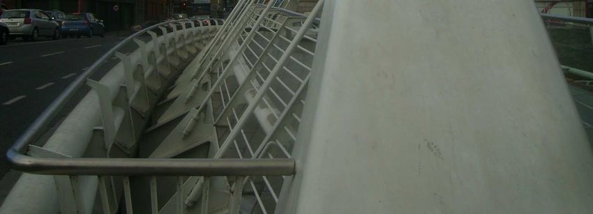
2 Aesthetics continuous steel arches giving a clean line over the
bridge deck, and the repetition of the cables at equal
Like any bridge, the aesthetics of the James Joyce
intervals providing regularity and sequence to the
Bridge can be assessed by looking at how it meets ten
bridge.
areas which are regarded as essential for a beautiful
bridge. Fritz Leonhardt, one of the most famous bridge
engineers of the 20th Century, outlined these ten areas
of aesthetics which should be considered during bridge
design [10], and it is with these in mind that the James
Joyce Bridge will be evaluated.
The design is dominated by a pair of steel arches
which are inclined outwards from the bridge deck and
curved in plan. The bridge deck can be seen to be
suspended from the arches by pairs of high tensile steel
cables which are inclined at the same angle as the
arches.
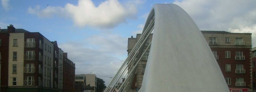
It is clear when looking at the bridge that the
arches are the main structural component and they are
sufficiently substantial in comparison to the other
bridge elements to emphasise this. The bridge deck is
slim and a glass parapet draws the eye from the visible Figure 3: Showing the high tensile cables and arch
part of the deck towards the clean, clear parapet which
runs along the edge of the pedestrian walkway. It becomes clear when analysing the bridge that it
was designed with the elevation in mind but, more
pressingly, also for the pedestrian or driver crossing the
bridge. Calatrava has evidently designed the bridge to
be an extension of the living and moving space which
we see in the city, with public squares and tiny parks
amidst the urban landscape. The James Joyce Bridge
has not been designed as just a crossing from one part
of the city to another, but to be enjoyed and appreciated
as an extension of the city, with public benches lining
the walkway from which stunning views of the banks
of the Liffey can be appreciated.
The finishes and refinements needed to be paid
close attention along the walkway. A stainless steel
handrail runs along the walkway, and the footpath
Figure 2: View of the bridge from upriver comprises sections of both smooth paving slabs and
transparent glass, helping to distinguish the walkway
The components of the bridge are slim and sleek, from the tarmac road. There are no street lamps along
making for an attractive river crossing for pedestrians the bridge; these would ruin the order and aesthetic
and vehicles alike. The ratio of voids and masses is integrity of the bridge. Instead there are luminaries at
well balanced, with the arches peaking 6m high above floor-level and along the arches above head height,
the deck so that a well-sized gap is created, making the which makes for a spectacular view of the bridge at
bridge appear light and not cumbersome on the night as it is lit up, visible from all along the river.
landscape. The proportions of the steel members used The way in which the arches are inclined creates a
in the arches and in the members which run along the passageway for the pedestrian under which one can
cantilevered pedestrian walkway are appropriate in walk, and could reduce the feeling of exposure which
emphasising the form of the bridge; the arches are one may feel while on a bridge. The pedestrian may
larger in size that the steel along the deck, showing that therefore be more inclined to spend time on the bridge,
the arches are more structurally important. making use of the sitting area or enjoying the view
The cables which suspend the deck from the which is framed by the steel arches.
arches are arranged in pairs and at regular intervals The bridge which Calatrava has designed is an
along the span. By arranging the cables in pairs there experience to be enjoyed and the opportunity has been
can be larger voids between the cables which can taken to sculpt a form which appears as though it rises
remain thinner and less noticeable to the eye. from the river, as the enormous arches emerge into
In a bridge which is deemed to be aesthetically sight. They are as much a piece of artwork as they are
pleasing one of the key points as outlined by Leonhardt structural features. Whilst the bridge is integrated with
is that there should be an easily identifiable order to the its surroundings, it still stands out as a landmark and
bridge, without too many confusing planes, lines or remains a feature of the area.
edges. In elevation the bridge has a clear form, with the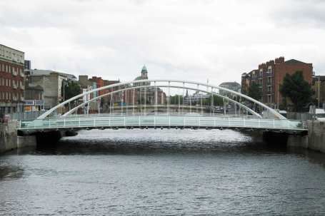
2.1 Summary of Aesthetics                                     cantilever outside of the longitudinal girders to give the
                                                              pedestrian walkway [5].
     In designing the James Joyce Bridge Calatrava has
found a good balance between simplicity and
complexity, with the inclined arches being the obvious
structural feature, while the cantilevered walkway with
the careful refinements adds another point of interest.
Although not magnificent in its span or of monumental
proportions, the James Joyce Bridge is a modest
addition to the Liffey bridges and an attractive,
functional and beautiful bridge.
                                                               Figure 5: Cross section through bridge at mid span,
3 Construction                                                                  with dimensions
     The construction of the James Joyce Bridge was
faced with many constraints; the city centre location,             All of these deck elements were pre-fabricated off-
the busy and narrow quays, the tidal nature of the river      site in Belfast by Harland & Wolff, transported to
and the geotechnical conditions. There were also a            Dublin and lifted into position onto the temporary
number of complex operations concerning the fixing            deck-support. The fabrication of these parts was
and welding of members, which it was found delayed            delayed, however, due to difficulties encountered by
work.                                                         the fabricator in making welds to a particular form of
     The first stage of construction was the local            joint. The fabricator refused to proceed until the
reduction in height of the existing quay walls to allow       engineering design was amended, and even when this
the construction of the abutments and temporary               was done there were still significant costs incurred by
cofferdams in the river at each abutment. This created a      the contractor [6].
dry working area around the abutments which can be                 The huge steel arches were manufactured on what
dismantled and removed once construction is over. A           is thought to be the largest horizontal hydraulic press in
temporary platform was constructed on piled                   the world, in order to produce the complex multi-axis
foundations in the river for offices, storage and plant       bends which were required by the design [7].
access.                                                            The most complex and most interesting phase of
                                                              construction was the lowering of the bridge deck into
                                                              place. The lifting process has been outlined with
                                                              reference to Campbell Scientific [2]
                                                                   Once the deck was constructed it was
                                                              incrementally lowered using computer-controlled
                                                              hydraulic jacks so that the correct deflection of the
                                                              bridge was achieved. A computer monitoring system
                                                              was chosen because the alternative (having a man
                                                              stood at each of the 56 positions to manually operate
                                                              the jacks) was considered too physically tiring and too
     Figure 4: Aerial view of James Joyce Bridge.             dangerous, as the men would be stood underneath the
                                                              structure throughout the load transfer.
     There were considerable delays at the start of                With the deflection of the bridge varying along its
construction due to unforeseen ground conditions. A           span from 25mm at the abutment to 105mm at mid
buried river lead to extended piling and so construction      span, the deck needed to be lowered at fourteen
was slow to start. Whilst at other points along the           differential rates, each controlled by a unique
Liffey there is rock, at the location of the James Joyce      monitoring system developed for the operation.
Bridge there is gravel and boulders and alluvium which        Displacement transducers were placed at 56 locations
can be conducive to buried rivers.                            along the deck, adjacent to the hydraulic screwed rams
     It was necessary to construct a temporary bridge to      controlling the lifting movement. It was necessary to
support the weight of the deck during construction and        ensure that the jack heads allowed longitudinal
during the installation of the inclined steel arches, until   movement of the bridge since during the process of
the arches were able to take the weight of the deck. A        reducing the hog in the deck its length increased by
working platform needed to be piled for the deck to           6mm. For this reason a temporary sliding face was
rest on and manual jacks were used to give the hogged         attached to two-thirds of the jack heads.
shape.                                                             Once the deck had been lowered to 60% of its final
     The bridge deck consists of box sections of              position all of the pressure in the hydraulic jacks was
constant depth but varying width, which is greatest at        relieved by the tied arches and the deck became
mid span. Transverse girders span between and                 supported.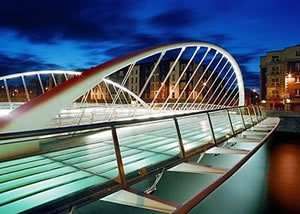
A complication which had to be overcome during
this process was that the working platform beneath the
deck flooded twice a day due to the tidal reach of the
sea, and so work had to be postponed at these
occasions. This slowed down construction and caused
particular inconvenience during the deck-lowering
process, which had to be stopped just one hour into the
operation.                                                    Figure 7: Load Path diagram, showing tied arches

                                                                 The piling process encountered difficulties which
                                                            led to the project coming in later than anticipated. The
                                                            extended piling was due to unforeseen ground
                                                            conditions; a buried river which had not been
                                                            accounted for in the geological studies performed pre-
                                                            construction.

                                                            5 Loading

Figure 6: Showing the connection between the cables         The bridge will be analysed in accordance with BS
               and the bridge deck                          5400; for the most part it is the British Standards which
                                                            are referred to for projects in Ireland. The loads
     The pairs of cables are stainless 40mm special         considered will either be for the most onerous case at
                                                            mid span of the bridge, or an average value for the
grade Macalloy SC460 cable [8], and are connected to
                                                            length of the bridge for modelling the bridge as a
the steel arches by high tensile steel hangers. These
                                                            whole. The appropriate safety factors and loads will be
cables can exhibit a conventional elastic stretch and an
                                                            applied
initial stretch of between 0.10% and 0.75% of the cable
length, depending on the magnitude and frequency of
loading.                                                    5.1 Dead Loads and Superimposed Loads
     Due to delays incurred during construction, the             The assumed dead load of the bridge components,
process took 6 months longer than planned, and came         which includes the weight of the box girders,
in well over budget. The project cost an estimated          cantilevered girders, concrete layer, asphalt road
€9million, and was opened on 16 June, or Bloomsday,         surface, and the glass/paved pedestrian walkway, has
2003. Bloomsday is an annual celebration in Dublin          been calculated to be an unfactored load of 184kN/m
which commemorates the life and works of James              length of the bridge. This includes superimposed loads
Joyce. The bridge has since been a part of the              such as the cables themselves, parapets etc.
celebrations, which includes readings and re-                    The bridge must be designed to be able to
enactments of passages from Joyce’s various works.          withstand the load conditions which, when applied,
                                                            achieve the most adverse effects. Loads during
4 Foundations and Geotechnics                               construction should not need to be found since a
                                                            temporary deck was constructed to support the weight
     The ground conditions were of great influence in
                                                            of the bridge during construction, with hydraulic jacks
informing the design of the bridge. At this point along
                                                            for supports.
the River Liffey the ground mainly comprises gravel
                                                                 The safety factors used are γfL (partial load factor
and boulders, whereas elsewhere there is hard rock.
                                                            specific to load) and γf3 (allowing for possible
This meant that a conventional arch design was not
                                                            inaccuracy in analysis of bridge). For SLS γf3 is 1.00,
suitable, since the lateral thrust exerted on the ground
                                                            and 1.10 for ULS (for steel bridges).
by the abutments would not be able to be withstood by
the banks on either side [2]. For this reason a pair of
tied steel arches was chosen for the main structural        5.2 HA Loading
element, which transfers the vertical load into to thrust        The main live loading which is exerted on a bridge
force directed towards the centre of the ties.              comes under HA and HB loading. HA loading consists
     There was still the requirement for piling into the    of a uniformly-distributed load acting over a notional
banks for the abutments, as well as for the temporary       lane in addition to a KEL located at the position which
working platform and 900mm diameter bored cast in-          gives the most adverse effects. This type of loading is
situ piles were used. As previously mentioned,              representative of heavy, fast-moving traffic with impact
cofferdams were constructed to create a dry working         factors included (such as bouncing of heavy trucks).
area for the construction at the banks [5].
Since the minimum width of the carriageway is 25m where no load is exerted. This allows for the safe
13m on the James Joyce Bridge, it makes sense to take distance either side of the vehicle which would be
this as the width of bridge to be used in finding the given. Since the James Joyce Bridge is only 40m in
number of nominal lanes, since it gives the largest length, it can be taken that an HB vehicle would be the
force per metre squared, and therefore is the most only vehicle on the bridge in the lanes which it
conservative. A bridge of length 40m gives a load per straddles, wit 1/3 HA loading over the remaining two
metre length of lane of 28.37kN/m. lanes.
W=336(1/L)0.67
= 28.37kN
A carriageway width of 13m gives 4 nominal
lanes, each lane of 3.25m, and so the force per metre
squared of carriageway is 28.37/3.25 = 8.72kN/m2. Figure 9: Diagram showing HB loading over the
This load, when factored, is to be applied to two bridge and HA loading
notional lanes of traffic, and 0.6α2 of this value to be
applied to the other two notional lanes, so as to obtain
the most adverse effects. The value for α2 has been 5.4 Braking Load
calculated as 1.00 and so 5.232kN/m2 will be applied to A horizontal force of 8kN/m along a single
the remaining two notional lanes. The KEL of 120kN is notional lane added to a 200kN force. For HB loading
to be applied at the most adverse location over two it is sufficient to take 25% of the total nominal HB load
notional lanes and a third of this applied as a KEL over applied over just 2 axles. Accidental skidding is taken
the remaining two lanes. The load factor to be applied as a single point load of 250kN acting horizontally in
to HA loading γfL= 1.25 for ULS. any direction in one nominal lane only.
The lanes which would give the most adverse
effects by way of the largest bending moments and
largest stress in the bridge deck are the two central 5.5 Pedestrian Load
lanes. Since the bridge is longer than 36m, the nominal
load of 5kN/m2 is multiplied by a factor k, which is
calculated by:
no min al HA udl for bridge length
k =
30 kN / m
26 kN / m
Figure 8: Showing HA loading with KEL over the =
30 kN / m
nominal lanes = 0.866
Therefore 5 x k = 4.33kN/m2 pedestrian loading on
5.3 HB Loading the cantilevered walkways.
This type of loading represents an abnormal truck
load on the bridge which may be transporting a long, 5.6 Parapet load
wide or heavy object. This may require special means
It can be seen that a parapet separates the road and
of transportation or transport arrangements, such as an
the high tensile cables to avoid collision of vehicles
escort or certain lanes being shut.
into the structural element which suspends the deck
Since the lane width for an HB vehicle is 3.5m, on
from the steel arches. The parapet must be able to
the James Joyce Bridge the vehicle would need to
withstand 25 units of HB loading colliding with it. It
straddle two lanes, since notional lane width is 3.25m.
can be seen to be made from steel and is slender, so it
It would be likely that the vehicle would straddle two
can be assumed that the protection is reliant on the
of the outside lanes, since the bridge carries two lanes
plastic deformation of the parapet to absorb much of
of traffic in each direction, but for worst case loading
the force from a collision. This does mean that the
the vehicle will be modelled to straddle the two central
section of parapet needs to be replaced after a collision.
lanes.
The associated safety factor γfL is 1.25 i.e. for load
A 45 unit HB vehicle exerts 112.5kN per wheel
combination 4 for ULS.
nominally, with the distance in this case between the
The parapet along the edge of the pedestrian
two front and two back axles being 6m, so as to
walkway which overlooks the river can be seen to be
calculate for the worst case of loading. With 16 wheels
made from glass, with steel members between each
the HB load is 1800kN.
glazed pane. This parapet must also be able to
It is also modelled when considering HB loading
withstand the load from pedestrians, which is 1.4kN/m
that in front and behind the HB vehicle there is a gap of
run of parapet.5.7 Natural Frequency The solid horizontal protected area is taken as
2.5m (the height of live load) + 1.4m = 3.9m multiplied
The vibration of a bridge due to pedestrians and
by the length of the bridge, 40m.
vehicles is an important factor which needs to be
The Coefficient of discharge is taken as 1.30,
considered. An ideal natural frequency, f0, will be
which has been chosen since it is the minimum
within the range of 5Hz and 75Hz, since it has been
allowable coefficient for decks supported by box-
found that frequencies outside of this range is off-
girders. The b/d ratio for the James Joyce Bridge would
putting for users of the bridge and can cause damage to
suggest a much lower CD, but 1.30 is the minimum
the bearings and supports. The equation for natural
allowed. This could be because the deck is particularly
frequency is:
EI slim for this bridge, as the steel arches support much of
ω n = (β n l )2 the load.
ml 4
A value for Pt can therefore be found:
Where (βn.l)2 = 22.373 for clamp/clamp conditions
for the bridge model, and (βn.l)2 = 15.42 for clamp/pin
end conditions. This is for one mode of vibration. The Pt = 0 .613 × 31 .68 2 × (3 .9 × 40 )× 1 .27
factor is dependent on the end conditions and is a
= 120kN
factor of fixity and stiffness of the bridge. = 3.05 kN / m length of bridge
The I value has been calculated as 0.54m4. The
5.8.2 Nominal Longitudinal Wind Load
mass per metre length of the bridge has been calculated
The nominal longitudinal wind loads are found in
as 18779kg/m. Therefore the natural frequency for the
BS 5400 and are exerted on the bridge superstructure
clamp/clamp condition ωn = 50.26Hz and for the
and the bridge live load, and derived separately. For
clamp/pin condition ωn = 34.6Hz, both comfortably
the superstructure when live loaded, PLS is found by:
within the allowable range.
The effects of forced vibrations due to vandalism PLS = 0.25 ⋅ q ⋅ A1 ⋅ C D
are unlikely to be as serious on the James Joyce Bridge
as on more lightweight pedestrian bridges.
= 0.25 × 615.22 × 3.9 ×1.3
= 0.779kN
5.8 Wind Load For the superstructure with live load, PLL is found by:
The first part of wind loading to be considered is PLL = 0 .5 ⋅ q ⋅ A1 ⋅ C D
the maximum wind gust, Vd, and found by: = 0.5 × 615 .22 × 3.5 × 1.3
= 1.56kN
Vd = S g ⋅Vs
5.8.3 Uplift or Vertical downward force
Vs = Vb S b S a S d There is a nominal force associated with the effect
= 1.57 × 0.80 × 1.0 = 1.25 of differential pressures above and below the bridge
deck.
S g = S b ⋅ Tg ⋅ S h
' Pv = q ⋅ A3 ⋅ C L
= 23 ×1.05 ×1.05 ×1.00 = 25.35 where, as before, q is dynamic pressure head, A3
is the plan area and CL the coefficient of lift. Based on
The factors and their meanings can be found in BS b/d ratio the coefficient of lift has been found to be
5400. For the James Joyce Bridge the maximum wind 0.15.
gust is: Pv = 0.613 × 31.68 2 × (24.5 × 40) × 0.15
Vd = 25 .35 × 1.25 = 31.68ms-1 = 90.4kN
= 2.26kN / m lengthof bridge
This value does not exceed the allowable
maximum wind gust for a bridge carrying pedestrians, The combinations of wind load to be considered
of 35ms-1. are Pt alone, Pt in combination with +/- Pt and PL,
which is the longitudinal loading of which nominal
5.8.1 Horizontal wind load values can be obtained in BS 5400. The final
The Horizontal wind load Pt in N, acting at the combination to be considered is 0.5 Pt + PL +/- 0.5 Pv.
centroid of the part of the bridge under consideration is
given by:
5.9 Temperature Effects
Pt = q ⋅ A1 ⋅ C D
There are two important temperature effects in a
where q is the dynamic pressure head, 0.631VD2, bridge; an overall increase or decrease in temperature
and measured in N/m2, A1 the solid horizontal or a variation in temperature between top and bottom
protected area and CD the coefficient of discharge. surfaces. A change in the ‘effective temperature’ canplace extra load on the bearings of the bridge as the This equates to a force in each cable of 60kN, a
deck contracts or expands. A differential temperature substantial proportion of the normal force in each cable
above and below the bridge will induce stresses at the of 445kN. The cable will ‘feel’ an increased tensile
interfaces between materials. The road section of the force. Alternatively with a temperature increase of
bridge which carries the vehicular loads is of 26ºC the cables each feel a decrease in force of 78kN;
composite construction with steel box sections beneath the cables lengthen and the stress is reduced and this
a concrete and asphalt layer. means that less deck weight is taken by the cables and
The average annual temperature in Dublin was the deck supports itself to a certain extent, behaving as
found to be approximately 10ºC, with a minimum a beam. The cables and the deck must be designed to
recorded temperature of -12ºC and a maximum of be able to withstand these additional effects due to
30ºC. The tables found in BS 5400 which make temperature.
adjustments to the effective bridge temperature based A temperature difference between the top and
on the group into which the bridge falls and the bottom of the deck of 25ºC would induce an axial force
thickness of surfacing were used and these of 12MN within the deck. The differential temperature
temperatures adjusted accordingly. This gave a difference can be seen in Figure 13.
minimum effective bridge temperature of -10ºC and a
maximum 36ºC. Therefore the maximum contraction
which the bridge would have to withstand is:
δ = ∆T ⋅ α ⋅ l
( )
= −20°C × 12 × 10 −6 / °C × 40m
= −0.0096m contraction in length
δ = ∆T ⋅ α ⋅ 1
(
= +26°C × 12 × 10 −6 / °C × 40m)
= +0.012m expansion in length
The bearings at the ends of the bridge would need
to be able to move so that excess stresses are not
induced. In addition to this, the ties between the arches
would be subject to extra tensile forces when the
bridge deck expands. Expansion joints at the ends of
the bridge would be able to allow movement of the
deck. However, there may not be movement allowed at
the ends of the bridge, in which case stresses would be
felt across the deck.
The compressive stress induced in the deck can be Figure 10: Showing Temperature differences through
calculated by: the deck
σ = ε ⋅E 6 Strength
= 26°C × (12 × 10 −6 / °C )(200 × 10 3 )
= 62.4 N / mm 2 (stress in steel) 6.1 Load Combinations
σ =ε ⋅E
(
= 26°C × 12 ×10 −6 / °C 35 ×10 3 )( ) Table 1 Load Combinations
Loads included in Combination
= 10.92 N / mm 2 (stress in concrete) 1 All permanent loads plus primary live loads
(vertical traffic loads)
A blockage in the expansion joints would mean 2 Combination 1 plus wind, and any temporary
that this stress is felt as a compressive stress in the erection loads
deck, and this would need to be able to be resisted by 3 Combination 1 plus temperature and temporary
the deck. erection loads
Another factor which the temperature could affect 4 All permanent loads plus secondary live loads
is the tension in the cables which the bridge deck is (skidding, centrifugal, longitudinal and
suspended from. With a temperature decrease of 20ºC, collision loads) and associated primary loads
the change in stress in each cable is: 5 All permanent loads plus loads due to friction
σ =ε ⋅E at supports
(
= 240 ×10 −6 × 200 ×10 3)
= 48 N / mm 2 It is against these load combinations, in which the
loads are arranged so that the most adverse effects areachieved, that the strength of the bridge would need to strain in the most onerous cables is found using the
be designed. stress-strain relationship:
The strength of the bridge needs to be sufficient to σ
withstand all the aforementioned natural phenomena in ε=
E
addition to the existing dead load, superimposed load, = 378/210x103
live load, and accidental damage or acts of vandalism. = 0.18%
The strength of the main structural elements and the
connections between the elements can be calculated as This is an acceptable amount of strain, since in a
follows. The strength will be assessed using the cable of length 6.7m at mid span this gives an
Ultimate Limit State using load combination 1, and the extension of 10.72mm. It is reasonable to assume that
appropriate factors γfL and γf3 applied. the bridge has been designed to achieve a certain
HA loading will be used in the strength analyses, redundancy so that in the case of one of these cables
since it has been found to be greater than the HB snapping or being weakened from a collision or some
applied live load, therefore the more onerous case. other extreme loading condition, the bridge will not
collapse but the force be taken by the other cables. It is
6.2 High tensile cables also likely that a cable may be weakened through
fatigue or loading which the bridge may be subjected
The strength of the cables by which the bridge to throughout its lifetime. There will also be an amount
deck is suspended from the steel arches can be of pre-tension in the cables to account for strain due to
calculated. As specified earlier, the cables used were dead loads, and so only the live-loads will cause
Macalloy SC460, 40mm diameter. The load factors are extension of the cables.
as found in BS 5400. The moment experienced at the connection
If the dead load added to the live loads uniformly between transverse steel girders and the main bridge
distributed at mid span of the bridge when factored for deck can be calculated. This provides information on
ULS is 538kN/m, then the force in each cable can be the size and strength of the connection required, and
found. how this can be satisfied by number of bolts or strength
The cables are arranged in pairs, two on each side of weld.
of the deck at 2.353m centres. The cables which will be The moment experienced at the connection
modelled for the purpose of testing the strength are between cantilever and main deck occurs at the mid
those located at midpoint. The steel arches are curved span cantilever and can be calculated by:
in plan, so that getting closer to mid span the tensile
cables become increasingly less vertical, and so the wl 2
force in the cable increases so that the vertical = 369kNm for ULS, and shown as a bending
2
component of the force remains the same. At mid span
moment diagram as follows:
the cables are angled at about 60 degrees to the
horizontal. The HA loading KEL will be added to the
538kN/m UDL, and it has been assumed that the four
cables at mid span take this entire point load. This is a
conservative assumption, and is reasonable for design
purposes.
538kN / m × 2.353m + 2(120 + 0.6 × 120) = 1649kN
1544kN ÷ 4cables = 412kN Figure 12: Bending Moment diagram of cantilever
6. 3 Bending
The bending moments induced in the bridge deck
within the central box need to be calculated.
Table 2 Showing Load across bridge deck
Roadway Pedestrian Walkway
Load /m width 1216kN/m 820kN/m
Figure 11 Force in a single cable at mid span It is necessary to model the bridge in cross-section as a
continuous beam over the internal points from which
The tensile force in each of the mid span cables is the cables suspend the deck. There is a hogging
476kN, giving a stress in each cable of σ = 378N/mm2. moment present at the points at which the cables are
This is acceptable since the SC460 has a yield strength connected, and a sagging moment at mid span of the
of 460N/mm2. With a Young’s Modulus of 210GPa the central deck section. The cantilever sections reduce the
sagging moment at mid span of the deck, but thehogging moment is increased. The rigidity of the box = 131N / mm 2 (in hogging region)
sections will take the bending moment in the deck, and
the hogging moments will be resisted by stiff
connections between the cantilevers and the central
deck.
The hogging moment is calculated by:
wl 2 820 × 62
=
2 2
= 14.7 MNm
The sagging moment is calculated as:
− [(820× 6 ×12) + (1216× 9 × 4.5)] + [(820× 6 + 1216× 9) × 9]
= 34.5MNm
Figure 14: UDL over length of bridge and associated
Bending Moment Diagram
6.4 Force in steel arch
The steel arches have been assumed to be of a
rounded rectangular cross section of dimensions
600mm by 300mm with a thickness of 25mm. This has
Figure 13: Bending Moment Diagram across width of been assumed from observational studies of
bridge deck per metre length photographic evidence.
The total axial force in each of the steel arches is:
It is also necessary to assess the arches which provide
the main structural support. The bridge is modelled so
(475kN / m × 40m ) = 9500 kN
that one end is clamped and one end pinned. 2
Considering the bridge in two halves so that the load This is assumed to act as an axial force through the
on a single arch can be found, the UDL along the arch, and the stress across the steel cross section can be
length of the bridge is 475kN/m, which creates a calculated as:
hogging moment at the clamped end and a sagging
9500kN
moment towards the other end of the bridge. In reality σ =
the points at which the deck is suspended by cables 42500mm 2
would reduce the sagging bending moment at the = 223N/mm2
connections, and the tension in the cables toward the
clamped end of the bridge would be decreased. This represents the stress at ULS, and so it can be
Another point to note is that the bridge deck has seen that the steel arches are loaded to near their full
been designed to be hogged, so the effects of a sagging capacity. This is a conservative calculation and it is
bending moment would be reduced; this could have likely that the stress is different in the arches.
been done so that the deck can be made to be slimmer Additional bending moments may be present in the
and therefore decreasing dead weight and reducing the arches also, which would reduce their load carrying
load which the steel arches must carry. capacity.
As can be seen on the bending moment diagram,
the max hogging moment is 95MNm and the max 7 Serviceability
sagging moment 53.4MNm. This is used to calculate
the stress in the bridge deck cross section using the There are numerous methods of monitoring
formula: bridges such as the James Joyce Bridge so during its
M ⋅ y (53 × 10 )× 750
9 operational lifetime so that any changes in deflection,
σ= = stress in cables and superficial damage to collision
I 0.54 × 10 12 barriers and road surface can be monitored and, if
= 73N / mm 2 (in sagging region) necessary, action taken to amend the changes.
σ=
( )
95 × 10 9 × 750
0.54 × 10¹² 8 CreepCreep should not be a problem for the James Joyce second bridge is located too far away to have any direct
Bridge; the problem is more common to bridges where impact on the levels of traffic.
concrete constitutes the main structural material.
Although there is concrete present in the bridge deck
11 Conclusion
and in the abutments for the bridge, and creep in these
elements may pose problems, the main structural The James Joyce Bridge has been analysed and
material is steel which should not be affected. The steel assessed in accordance with the British Standards, and
box sections and girders will retain their strength in an evaluation of the aesthetics, construction, design,
spite of any shrink or creep of the concrete. and loadings has been provided.
This analysis serves to illustrate the work of one of
the world’s most inspired engineers, constructed at a
9 Durability & Vandalism
time when Ireland was at the peak of a fast-moving
The addition of provisions for resting and sitting period of large-scale expansion of its infrastructure.
space on the bridge means that people will be able to This expansion has arguably slowed down since, and
enjoy the bridge for prolonged periods of time. although it will soon be joined by Calatrava’s Samuel
However, vandals and hooligans may loiter on the Beckett Bridge, the James Joyce Bridge will stand out
bridge, and proceed to cause damage and defacement. as a feat of architecture and engineering across the city
Regular cleaning of the bridge’s gleaming features of Dublin and across the world, a cultural and artistic
should take place so that it remains attractive and beacon which commemorates the life of one of
welcoming. Ireland’s most prominent artistic and literary pioneers.
There are problems which can result from concrete
deck slabs such as deterioration from de-icing salts,
12 References
and this can affect the steel box sections underneath.
The steel may become stained and lose its aesthetic [1] PHILLIPS M. and HAMILTON A., Project
appeal. De-icing salts may be frequently dispensed in History of Dublin’s River Liffey Bridges, Bridge
the winter months in Dublin due to its northern Engineering 156, Issue BE4 December 2003, pp
European climate. 161-179.
The cables which suspend the deck from the steel
[2] Campbell Scientific, Lowering the James Joyce
arches are stainless steel, and so should be resistant to
Bridge at Blackhall Place, Dublin. Available from
excessive corrosion or damage from the weather, or
ftp://ftp.campbellsci.com/pub/csl/outgoing/uk/appl
from accidental damage.
ications/bridge%20lowering.pdf
The finishes and refinements in the pedestrian
walkway may need extra attention paid, since they will [3] CALATRAVA S., Information available from
need to maintain a clean and welcoming impression for http://www.calatrava.com/main.htm
the user. The glass flooring may not be as durable as
[4] JANBERG N, Structurae, Available from
the paved section for walking on, and so replacements
http://en.structurae.de/structures/data/index.cfm?id
may be necessary throughout the lifetime of the bridge.
=s0012071
10 Future Changes [5] Carillion Irishenco Ltd, Information available at
http://carillionirishencoltd.buaconsulting.com/Jam
The effect of the river on the bridge and its es_Joyce_Bridge.htm
abutments has not been discussed, but could be of
importance in the future. Erosion and damage to [6] ANON., Builder 'not entitled' to extra €6.4m for
Dublin’s O’Connell Bridge, further upstream of the bridge, Irish Times, Saturday 21st February 2009
James Joyce Bridge, has been noticed recently and to a [7] HEDERMAN M. P., Bloomsday at 100: two
less degree to the Butt Bridge. The damage is due to reflections on James Joyce's legacy. Available
the increasingly high tides which mean that water is from www.thefreelibrary.com/Bloomsday+at+100:
now splashing up and hitting the bridge at its parapet. +two+reflections+on+James+Joyce's+legacy-a011
It is possible that the James Joyce Bridge may be 7923560
susceptible to the same problems. However, the
aforementioned bridges are constructed from masonry [8] Macalloy Bar and Cable Systems, Information
and reinforced concrete respectively, and so may not Available at www.macalloy.com/projects/james-
be as resistant to the force and effects of the rising tides joyce-bridge-dublin
as the steel of the James Joyce Bridge. [9] CARBERY G., O’Connell Bridge Undergoes
It has been mentioned that the city of Dublin will Structural Repair, Irish Times, Thursday 28th
be welcoming the addition of a second Calatrava August 2008
bridge, to be constructed further east of the James
Joyce Bridge. This may reduce the traffic on the bridge [10] IBELL T., Department of Architecture and Civil
from current levels, although it is possible that the Engineering, University of Bath, Bridge
Engineering.You can also read