A Hierarchical State-Machine-Based Framework for Platoon Manoeuvre Descriptions
←
→
Page content transcription
If your browser does not render page correctly, please read the page content below
A Hierarchical State-Machine-Based Framework for Platoon
                                                                  Manoeuvre Descriptions
                                         Corvin Deboeser1 , Jordan Ivanchev1,2 , Thomas Braud1 , Alois Knoll2,4 , David Eckhoff1,2 , and
                                                                      Alberto Sangiovanni-Vincentelli3
                                                                                 1
                                                                                 TUMCREATE, Singapore
                                                                         2
                                                                          Technical University Munich, Germany
                                                                            3
                                                                              University of California, Berkeley
                                                                      4
                                                                        Nanyang Technological University, Singapore
arXiv:2104.05305v1 [cs.MA] 12 Apr 2021

                                                                                          April 13, 2021

                                         Abstract                                                        dynamics level for smooth and energy-efficient driving.
                                                                                                         The second category, in contrast, centres around col-
                                         This paper introduces the SEAD framework that sim-              laboration and communication strategies, for instance,
                                         plifies the process of designing and describing au-             how an additional vehicle joins an existing platoon.
                                         tonomous vehicle platooning manoeuvres. Although a              Within the second category, researchers have inves-
                                         large body of research has been formulating platoon-            tigated specific cases of collaborative driving in pla-
                                         ing manoeuvres, it is still challenging to design, de-          toons. Most papers focus on the specific details of one
                                         scribe, read, and understand them. This difficulty              manoeuvre and optimise it to a great extent in terms
                                         largely arises from missing formalisation. To fill this         of stability (the trait of a manoeuvre not to lead to
                                         gap, we analysed existing ways of describing manoeu-            dangerous traffic situations) or execution time.
                                         vres, derived the causes of difficulty, and designed a
                                                                                                            Although most papers draw on the description of
                                         framework that simplifies the manoeuvre design pro-
                                                                                                         manoeuvres through finite state machines, there is no
                                         cess. Alongside, a Manoeuvre Design Language was
                                                                                                         consensus or convention among researchers how to rep-
                                         developed to structurally describe manoeuvres in a
                                                                                                         resent manoeuvres. This heterogeneity aggravates the
                                         machine-readable format. Unlike state-of-the-art ma-
                                                                                                         comparison of manoeuvres and requires researches to
                                         noeuvre descriptions that require one state machine
                                                                                                         constantly adapt to new conventions. Besides, the de-
                                         for every participating vehicle, the SEAD framework
                                                                                                         scription of manoeuvres through mere state machines
                                         allows describing any manoeuvre from the single per-
                                                                                                         requires multiple synchronised yet independent state
                                         spective of the platoon leader. We hope that the
                                                                                                         machines, one for each participating vehicle. Design-
                                         SEAD framework will pave the way for further re-
                                                                                                         ing and reading these state machines can become chal-
                                         search in the area of new manoeuvre design and opti-
                                                                                                         lenging even for simple manoeuvres. The objective of
                                         misation by largely simplifying and unifying platoon-
                                                                                                         this work is to provide a framework that simplifies and
                                         ing manoeuvre representation.
                                                                                                         formalises this description.
                                                                                                            The proposed framework follows four principles:
                                                                                                         Standardisation, Encapsulation, Abstraction, and De-
                                         1    Introduction                                               coupling (SEAD). Standardisation ensures a common
                                                                                                         terminology among all areas within the framework
                                         Multiple challenges must be solved along the way to a           and all researchers applying it. To take advantage
                                         globally optimised and highly automated urban traffic           of the repetitive occurrence of action-sequences in
                                         system. While the past has seen a large body of re-             various contexts, the Encapsulation principle allows
                                         search and technological innovation on AV, platooning           grouping such repetitive patterns into re-usable mod-
                                         as a concept is still in its early stages. With the capa-       ules. Since some patterns may contain sub-patterns,
                                         bilities of vehicular awareness and communication in            the Abstraction principle leads to recursive encapsu-
                                         place, research can now start building elaborate pla-           lation which allows considering manoeuvres and their
                                         tooning strategies to leverage on those technological           building blocks on different levels of detail. The De-
                                         advancements.                                                   coupling principle, finally, separates the control of the
                                            A specialised body of research is concerned with for-        manoeuvre from its execution. This allows describing
                                         mulation of collaborative driving manoeuvres whereas            manoeuvres exclusively from the control-perspective
                                         research is split into two major categories. The first          of the platoon leader while the framework ensures the
                                         category optimises driving behaviour on the vehicle’s           correct execution behaviour. The SEAD framework

                                                                                                     1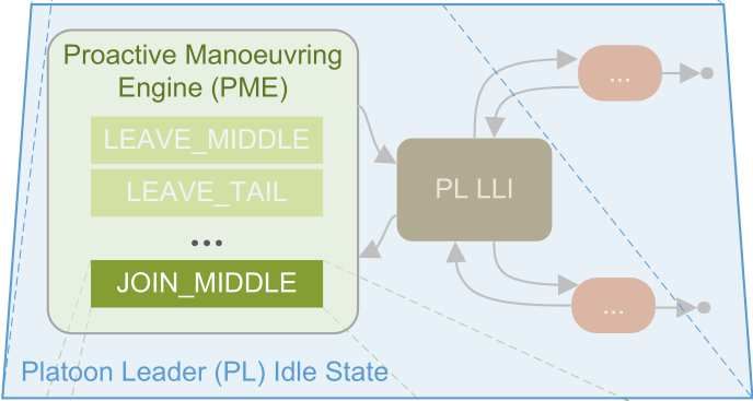
may serve future research as a point of reference and splitting strategies and to optimise traffic globally in-
tool to facilitate further manoeuvre investigations.  stead of locally. The combination of such systems
  In summary, the contributions of this article are:  yields an AHS. Due to its complexity, the structure
                                                      of the AHS is split into five hierarchical layers [1, 2].
  • We survey and structure the complex landscape Each layer fulfils a mutually exclusive task as shown
     of AV manoeuvre research, identify shortcomings, in Figure 1.
     and derive requirements for a new framework.

  • We present SEAD, a novel AV manoeuvre frame-
    work to significantly simplify the process of ma-
    noeuvre modelling.

  • We make a library of manoeuvres publicly avail-
    able, in both human-readable and machine-
    readable formats.

   The remainder of this article is organised as follows:
First we give an extensive summary of related work
in the domain of AV manoeuvre modeling (Section 2).
From this we derive in Section 3 requirements and
                                                          Figure 1: Control hierarchies of the platooning control
principles that a common framework should fulfil and
                                                          system (summarized from [1–3])
follow. Section 4.4.1 introduces our new SEAD frame-
work. Finally, in Section 5 we discuss possible exten-
sions and conclude the article.                             At the highest level of the hierarchy, the Network
                                                          Layer is responsible for optimizing the overall travel
                                                          time of all vehicles and the traffic flow in the entire net-
2 Related Work                                            work   [2]. It is aware of all autonomous vehicles in the
                                                          road network and the current and predictable traffic
The concept of an Autonomous Highway Systems situation on every road [1, 2]. To optimize travel time
(AHS) was first introduced by Varaiya in 1993 un- and traffic flow, it balances the traffic load on each
der the name Intelligent Vehicle/Highway System road by determining the ideal path for each vehicle
(IVHS) [1], promising increases in safety and in that travels from a defined origin to a defined desti-
highway capacity without the need of building new nation [1, 4]. For the case of IVHS, the network only
roads. These advantages emerge from two conceptual consists of the highway. The Link Layer is more de-
changes as compared to a conventional highway: 1) centralized and implemented by a controller for each
the application of vehicle platooning and 2) a global road segment [1]. The controller ensures a smooth
optimisation of traffic flow and travel times through traffic flow on its road segment by distributing the
a layered control structure.                              traffic vehicles among lanes [2]. Besides determining
   A platoon is composed of a leader and at least one a dedicated lane for each vehicle or platoon, it also de-
follower whereas, in most publications, the leader is termines the target size and velocity for platoons on
the first vehicle in the upstream direction. The ma- that section [3]. For an IVHS, the road segmentation
jor impact of platooning for an increased highway ca- is realized by dividing the highway into segments of
pacity is the decreased inter-vehicle distance within equal length. These two layers are implemented in the
platoons (intra-platoon distance d) as compared to infrastructure and part of the roadside system. The
the inter-vehicle distance outside of platoons (inter- layers below belong to the vehicle system, meaning
platoon distance D) [1]. As shown in [1], platooning that every vehicle is equipped with modules to realize
may increase road capacity by up to a factor of three. the tasks of the three layers described below.
   In the platooning logic, the leader sets the platoon     At the highest hierarchical level of the vehi-
speed and coordinates the manoeuvres performed by cle system is the Platoon Layer or Planning and
the platoon, for example splitting a platoon into two Coordination-Layer. As a free vehicle, this layer de-
platoons (Split manoeuvre) or merging two platoons termines actions to fulfil the path and lane directives
into one (Merge manoeuvre). The followers follow imposed by the layers above [3]. Part of this task is
the preceding vehicle according to their Cooperative to determine lane changes, if a vehicle should join or
Adaptive Cruise Control (CACC) system and react leave a platoon [2]. As a platoon leader, this layer
upon commands issued by their platoon leader.             coordinates the actions with vehicles that are associ-
   Although platooning itself increases road capacity ated with the platoon either as followers or potential
and vehicle throughput, it may become more effective joiners [1]. As a platoon follower, the platoon layer
when applying additional higher-order strategies that collaboratively performs action protocols which are
leverage on the vehicle’s communication capabilities. initiated by the platoon leader [1, 3].
The interconnection of vehicles and infrastructure al-      The Regulation Layer and the Physical Layer are
lows to control optimal platoon forming, driving, and responsible for realising the trajectories computed by

                                                          2
the hierarchically higher layers. Control loops in the         hicles. Since both vehicles operate through the same
Regulation Layer compute actionable commands for               set of protocols, they can expect the other vehicle to
the actuators and minimise the errors reported by the          behave synchronously.
sensors in the Physical Layer [3].                               The representation in Figure 2 describes the be-
   The Platooning Layer, which is the focus of this            haviour as two separate FSM, each describing the pro-
publication, contains collaborative driving logic: Pla-        tocol for one role within the manoeuvre. FSM (a)
toons must be formed, maintained, and modified. Col-           shows the transition of a vehicle from one Idle State
laborative driving of multiple vehicles is described by        into another. After extending the state machine by
manoeuvres. Manoeuvres encompass the driving and               the transition from a free vehicle into a platoon leader
communication behaviour for all participating vehi-            through platoon formation, the entire behaviour could
cles in the form of manoeuvre protocols. As shown              be explained in one role-agnostic FSM. This FSM op-
in the subsequent sections, the description of manoeu-         erates on both vehicles independently and simultane-
vres is complex even for simple ones. Our work, thus,          ously. Both participating vehicles then operate fol-
aims to increase the comprehensibility and facilitate          lowing the same FSM schema, yet they are in differ-
the easy formulation of platoon manoeuvres.                    ent states during the manoeuvre and follow different
   A common way of describing these manoeuvre-                 paths through the FSM.
protocols are communicating finite state machines                This approach was shown by [5] and is illustrated in
e.g. [5–7]. In order to gain a better understand-              Figure 3 as an extension to the example in Figure 2.
ing of different manoeuvre description approaches              The dashed arrows were added to combine the two
we present a simplified example of the JOIN TAIL-              FSM into one.
manoeuvre from [3] shown in Figure 2. The JOIN
TAIL-protocol describes the process of a free vehi-
cle joining an existing platoon at its tail through two
CFSM.

                                                               Figure 3: Combined FSM that represents the JoinTail-
                                                               protocol as shown in Figure 9. The dashed arrows
                                                               establish the connection between the two state ma-
                                                               chines.

Figure 2: Example description of the JoinTail proto-             In the same manner as in Figure 3, it is possible to
col as communicating FSM (simplification of protocol           describe the entire behaviour of vehicles in one role-
from [3]). (a) behaviour of the joining vehicle, (b) be-       and manoeuvre-agnostic FSM, meaning that one FSM
haviour of the platoon leader. Rectangles constitute           would describe the entire platooning behaviour of a
the states and the arrows the transitions. States with         vehicle for all roles.
double-stroke are Idle States (i.e. starting and end-            Although FSM are the dominant way to describe
ing states of a protocol) and the ones with a single           manoeuvres in the current state of literature, re-
stroke are action states (i.e. states where an action is       searchers also applied other ways of illustration. The
performed).                                                    authors of [3] describe a manoeuvre in a role-agnostic
                                                               process flow-chart. From this chart, they deduct role-
   When a vehicle (Vehicle A) decides to join a pla-           specific state machines that are ultimately formulated
toon, it sends a join request to the leader (Vehicle B)        in the COSPAN (coordination-specification-analysis)
of the platoon (Transition 1, T1). B either rejects            system. COSPAN formalises CFSM to prove certain
(T2) or acknowledges (T3) the request. In the case             mathematical state machine properties such as com-
of rejection, both vehicles return to idle and the pro-        pleteness or reachability [8].
tocol terminates. If the request is acknowledged, A              In [9], the logical flow of manoeuvres is also de-
will wait for B to join the platoon. A moves to the            scribed as a role-agnostic flow-chart. Focusing on V2V
tail of the platoon. Once arrived at the tail, A at-           communication, however, this paper also provides ad-
taches to the platoon, starts following the preceding          ditional information flow-charts to describe the com-
vehicle (i.e. switch into CACC mode), sends a mes-             munication between the participating vehicles. In ad-
sage to B that the join is completed (T4), and transi-         dition to illustrations, the majority of papers describes
tions into the follower-Idle State. Upon receipt of the        the logical flow of events in manoeuvres through tex-
join-completion message, B updates the platoon infor-          tual descriptions e.g. [3, 5, 7].
mation and returns to idle. The protocol execution is            As mentioned above, most publications describe
complete and terminates.                                       manoeuvres as FSM whereas only a minority applies
   This description shows that state machines synchro-         other visualization and description principles. How-
nise through messages that are sent between the ve-            ever, although most manoeuvre descriptions use the

                                                           3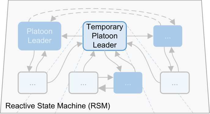
same methodologies, there is still a vast heterogene-            is only suitable for one-way messages.
ity among all existing publications. Two dominant                   The Minimal Protocol can be used for collaborative
sources of this heterogeneity are: 1) different levels of        awareness as well as manual platooning, meaning that
detail, and 2) verbally differing descriptions to repre-         a driver must manually initiate the joining or leaving
sent identical actions.                                          of a platoon. Within the platooning protocol, the
   Different levels of detail: Some manoeuvre de-                authors differentiate among three types of messages:
scriptions show a level of detail that reaches the regula-       Service Announcements, Service Requests, and Con-
tion layer with states such as Accelerate to Merge [3]           trol Data Messages. Service announcements are sent
or Set Speed to 30 m/s [5]. Other descriptions, or               by platoon leaders to advertise services, for instance,
sometimes even the same description, stay on a very              the availability to add another vehicle to the platoon.
high level within the platooning layer with states such          Service requests are, for instance, sent by free vehicles
as Car Splits [7] or Move To Position [10]. Due to               to platoon leaders to express the willingness to join.
these differences of abstraction level, FSM that po-             Control Data Messages are sent periodically by pla-
tentially describe the same behaviour are, in fact, sig-         tooning vehicles to maintain and update the integrity
nificantly different.                                            of the platoon.
   Differing verbal descriptions: Even if illustra-                 In [5], the WAVE Short Message Protocol
tions describe a manoeuvre on similar levels of detail,          (WSMP) [32] is applied to carry information on the
they may use different terminologies or different levels         CCH. The messages are of two types. The first type
of verbal abstraction for the same action. For exam-             are beacons. These beacons, like CAM, carry informa-
ple, the Join Tail-protocol was described in [10] and            tion about the vehicle state, e.g. the position, acceler-
in [3] in similar logical ways. In both descriptions             ation, and lane. Additionally, the beacon carries the
for the joining vehicle, a dedicated state equalises the         platoon ID and the current vehicle position in the pla-
speed of the platoon and the joining vehicle by decel-           toon if the vehicle is platooning. The position starts
erating or accelerating. While [10] describes this as            with 0 at the platoon leader and increments with each
Set Speed to 30 m/s and Catch-up and merge the pla-              vehicle in the platoon counting upstream. The sec-
toon from the back, [3] expresses the same process as            ond type is micro-commands. These are used to initi-
Accelerate to Merge. This poses a challenge when for-            ate and control platoon manoeuvres. While beacons
malising and comparing manoeuvres across different               are usually broadcasted, most micro-command mes-
publications.                                                    sages are unicasted or, if the manoeuvre involves mul-
   Besides these heterogeneities, we identified two              tiple vehicles, multicasted. The authors provide a set
additional factors that pose challenges when for-                of seventeen micro-commands to enable a multitude
mulating manoeuvres. First, repetitiveness intro-                of manoeuvres. To give the reader a more complete
duces pseudo-complexity, especially for those descrip-           overview Table 1 summarizes the research efforts in-
tions with high levels of conceptual detail. For in-             volving studying platoon manoeuvres that were con-
stance, the process for a vehicle moving to a cer-               sidered for this paper.
tain position requires both communication and phys-
ical action. The leader orders the joining vehicle to
move to a defined position. When at that position,               3     Requirements and Principles
the joining vehicle informs the leader about the ar-
                                                                 To relief the shortcomings described in the previ-
rival. These action-communication-patterns may oc-
                                                                 ous section, namely the challenges with comprehen-
cur repetitively within a manoeuvre FSM.
                                                                 sibility, compilation and comparison of manoeuvre-
   Second, since manoeuvres are mostly performed by              descriptions, we propose a framework for the universal
two or more vehicles collaboratively, the behaviour              description of manoeuvres that builds on the four prin-
for every participant is described in dedicated, role-           ciples of Standardisation, Encapsulation, Abstraction,
dependent FSM. Reading these coupled state ma-                   and Decoupling (SEAD). This framework will enable
chines requires a substantial effort as the reader must          researchers and engineers to easily define new or al-
manually synchronize the state machines to under-                ternative manoeuvres within the platooning layer Fig-
stand the collaborative process.                                 ure 1. First we will derive requirements for the frame-
   Another very important aspect of platooning is com-           work design from the identified limitations, then we
munication. The Join Tail-protocol description in Fig-           will define goals that the framework should fulfil, and
ure 3 shows the necessity for message transfers be-              postulate the overarching design principles to achieve
tween participating vehicles. V2V standards, how-                the design goals. Figure 4 provides an overview of the
ever, serve only collaborative awareness and are not             interrelations among deficits, goals, and principles.
sufficient for this case of collaborative driving. Re-              The SEAD design framework aims to resolve the
searchers have developed various ways of formalising             major shortcomings that state-of-the-art manoeuvre
this communication while complying with the existing             descriptions face. The subsequent list summarises the
standards. The authors of [31] propose two protocols:            identified deficits and defines the scope of problems
A Minimal Protocol and a Full Platooning Protocol.               the proposed framework should solve.
While the Full Platooning Protocol is equipped for se-
cured two-way communication, the Minimal Protocol                  • Varying conceptual depth: Varying levels of con-

                                                             4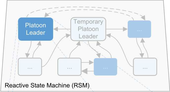
Table 1: Research publications regarding platooning manoeuvres
Reference Manoeuvres Additional Information Cat*
Lu & Hedrick 2003 [11],
Merge Design of controller for longitudinal merging, virtual platoon to pre-compute trajectory before manoeuvre P
Lu et al. 2004 [12]
Platooning for non-autonomous trucks with CACC technology
Nowakowski et al. 2016 [13] Merge, Split P
and V2V communication, manoeuvres performed by drivers
Designing and investigating the JoinMiddle manoeuvre with
Segata et al. 2014 [10] JoinMiddle (FSM) P
various interference scenarios and communication packet loss
Hsu & Liu 2004 [14] LaneChange Proposes manoeuvre to LaneChangeAndFollow for higher efficiency P, R
Hsu & Liu 2008 [15] LaneChange Investigates LaneChange options: simultaneously and time delay with varying inter-platoon spacing P, R
Kazerooni & Ploeg 2015 [16] Join, LaneReduction, GapOpen, GapClose Design of interaction protocols for LaneReduction and JoinMiddle, Analysis of velocity profiles P, R
Rajamani et al. 2000 [7] Join, Leave, LaneChange (FSM) Lateral and longitudinal control for Merge and Join, and LaneChange P, R
Rapid high-speed lane change for obstacle avoidance,
Best 2012 [17] - R
proposal of open-loop controller for steering instead of emergency braking
Choi & Swaroop 2000 [18] - Assessing coordinated emergency braking in platoons R
Proposal of safety-ensuring controllers for Merge, Split,
Merge, Split,
Frankel et al. 1996 [19] R
LaneChange
and LaneChange as FSM, textual description of manoeuvres
Godbole et al. 1995 [2] Join, Leave (textual) On- and off-ramp in AHS with dedicated lane for AVs R
Goli & Eskandarian 2014 [20] Merge, LaneChange Multi-merge manoeuvre (multiple vehicles at one), lateral trajectory generation and execution via PID R
Huang & Chen 2001 [21] Merge, Split Investigates the safety of Merge and Split for emergency braking into different stages of the manoeuvres R
Merge, Leave,
Kato et al. 2002 [22] Investigation of velocity profiles for merging, obstacle avoidance, leaving, and Stop&Go R
LaneReduction
Longitudinal control laws with focus on safety that can be
Li et al. 1997 [23] - R
adjusted through parameters for changing external conditions
Murthy & Masrur 2016 [24],
Emergency Brake Coordinated emergency braking in platoons considering the weakest vehicle in the platoon R
Murthy & Masrur 2017 [25]
Naranjo et al. 2008 /citenaranjo2008lane LaneChange Applying fuzzy controller lateral and longitudinal control in LaneChange manoeuvre for overtaking R
Merge,
Concept of virtual leader to command synchronised lane changes,
Rai et al. 2015 [26] R
LaneChange,
collision avoidance through potential-field controller
Overtake
LaneChange,
Manoeuvre to directly switch from one platoon to other platoon on
Sun et al. 2003 [27] R
PlatoonChange,
adjacent lane, controller design for gap making and closing
GapOpen, GapClose
Controller that couples braking and lane changing in emergency situations
Swaroop & Yoon 1999 [28] Emergency Brake and Emergency LaneChange R
through V2V communication for higher safety
Usman & Kunwar 2009 [29] Overtake Methodology for online generation of driving trajectories for overtaking manoeuvres R
Wang et al. 2017 [30] JoinMiddle, GapOpen, GapClose Trajectories for JoinMiddle for minimizing carbon emissions R
* Focus of the paper, C = Communication, R = Regulation Layer, P = Platooning Layer
For the SEAD framework to achieve practicality
while resolving these deficits, we defined three design
goals. The goals outline how we define practicality for
the framework and give guidance in making all design
decisions. The three qualitative goals are Flexibility,
Simplicity, and Stability.
• Flexibility: The framework must be capable of
describing all manoeuvres in the current state of
Figure 4: Relations of Key Deficits, Design Principles, literature. Any design decision, thus, must en-
and Design Goals for creating the SEAD framework. sure that the flexibility of describing manoeuvres
is maintained and that restrictions are minimised.
ceptual depth within and among manoeuvre de- • Simplicity: The prime use case of the framework
scriptions require to re-frame the manoeuvres be- is reading and formulating new or alternative ma-
fore comparison. noeuvres. Any design decision, thus, must pro-
mote the simplicity of reading and formulating
• Differing verbal descriptions: Differing verbal de- manoeuvres.
scriptions for equivalent conceptual components
require the manual alignment of terms before • Stability: The stability of manoeuvre designs is
comparison. crucial, meaning that the design shall not allow
for manoeuvres that end in an undefined state
• Repetitive patterns: Repetitive action- if unexpected driving situations occur. Any de-
communication-patterns within and among sign decision, thus, must foster the stability of
manoeuvres make manoeuvres more complex to manoeuvres for any possible interruption or ex-
read and tedious to be described. ception.
• Complex synchronisation: The complex synchro- Given the postulated requirements, we derived four
nisation between multiple role-specific FSM in major design principles that help to resolve the cur-
one manoeuvre is challenging. This makes it hard rent shortcomings and to fulfil the design goals. These
to understand the collaborative aspect of a ma- can be summarised under the four terms Standardi-
noeuvre. Besides, it poses the threat of unstable sation, Encapsulation, Abstraction, and Decoupling.
states due to unforeseen circumstances. The subsequent sections explain these principles in
5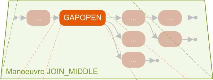
greater detail and interrelate them with the estab-             arbitrarily complex structures whereas every level of
lished design goals and identified deficits.                    conceptual depth can be designed separately without
   Standardisation                                              the need to operate on different levels at once. Ab-
   As stated above, one prime issue in defining ma-             straction helps to resolve the deficits of varying con-
noeuvres is the vastly varying terminology for equal            ceptual depth and handling repetitive patterns.
conceptual components. These components can be                     As every system that re-frames complexity through
states within an FSM, V2V platooning messages or                hierarchical depth, our framework imposes certain
inherent reasons for state transitions such as au-              restrictions. Nevertheless, it shall fulfil the design
tonomous decisions. Our framework resolves the lack             goal of Flexibility, meaning that every abstraction
of standardisation by introducing a finite set of sym-          will be carefully evaluated. On the other hand, the
bols for these conceptual components. More specifi-             Abstraction principle fosters Simplicity as the major
cally, the SEAD framework provides a syntax for de-             part of the manoeuvre design process takes place at
scribing vehicle actions, messages, and internal state          the higher levels of abstraction. This allows building
transition triggers. The main requirement for this              highly complex manoeuvres with relatively low effort.
standardisation is the universal comprehensibility re-             Decoupling
gardless of context or background.                                 Lastly, the Decoupling principle will allow describ-
   The principle of Standardisation will mainly be af-          ing complex manoeuvres entailing two or more vehi-
fected by the design goals Flexibility and Simplic-             cles from the perspective of the platoon leader. The
ity. Although Standardisation will introduce syntactic          SEAD framework, and specifically the Encapsulation
rule sets, the standardised framework must be capa-             principle, ensures that this single-sided description
ble of expressing a sufficient conceptual depth not to          suffices to describe the behaviour of all vehicles. More
obstruct the Flexibility goal. Besides, the Standard-           specifically, the utilized master-slave structure leads
isation should also promote Simplicity, meaning that            to a general universal description of the reactive be-
the standardised terms must be intuitively comprehen-           haviour of the slave (platoon followers or free vehi-
sible and easy to grasp without the need for extensive          cles) while manoeuvres are only defined and steered
preparation. The aim is that a person with no prior             by the master (platoon leader). This principle, in con-
experience with the SEAD framework must be able to              sequence, resolves the need for synchronising multiple
understand the manoeuvres formulated using it.                  manoeuvre descriptions.
   Encapsulation                                                   Decoupling will considerably facilitate the process
   Throughout manoeuvre descriptions, we identified             of reading and describing manoeuvres as both actions
various repetitive patterns that include vehicle actions        must only be performed from the leader perspective.
and inter-vehicle communication. The principle of En-           This greatly drives the goal of Simplicity. However,
capsulation will help pack these patterns into reusable         designing the reactive behaviour of the slave-vehicles
blocks whereas one block may contain autonomous                 must be very comprehensive and elaborate in order to
activities of one vehicle or synchronised actions of            fulfil the design goal of Flexibility.
multiple vehicles. Moreover, these sub-manoeuvres
will mainly comprise actions and states of equal con-
ceptual depth. This helps in resolving the problems             4    Framework Building Blocks
of varying conceptual depth, repetitive patterns, and
complex synchronisation.                                        In this section, we will give a detailed description of
   The Encapsulation will be influenced by all three de-        the building blocks that make up the SEAD frame-
sign goals. Following the design goal of Flexibility, the       work. Before we present each building block in a
Encapsulation of intertwined action-communication               bottom-up fashion, we will describe a few properties
patterns must not impose manoeuvre-design restric-              of the the system to facilitate its overall comprehen-
tions. Thus, sub-manoeuvres on the lowest level                 sion:
must express the most fundamental patterns exhaus-                 Scope: The described platooning framework does
tively. Thereby, Encapsulation will greatly promote             not include high level decision-making processes such
Simplicity as it will allow reusing behavioural pat-            as when to form a platoon or when to leave a platoon.
terns without the need for redesigning them. This               This is the task of the Link Layer Interface (LLI) and
requires equipping sub-manoeuvres with a suitable in-           could either be computed inside an autonomous ve-
terface that allows for integrating them into higher-           hicle or be given in the form of commands issued by
order structures. Lastly, to achieve Stability, the sub-        another controlling entity. The framework at hand
manoeuvres must be designed to always lead to pre-              will only cover the platooning layer itself.
dictable outcomes that can be handled by any context.              Stability: To ensure stability of the system, each
   Abstraction                                                  platooning manoeuvre has to end in a stable state for
   Extending Encapsulation, the principle of Ab-                all involved vehicles, regardless of manoeuvre’s suc-
straction will allow to reuse the encapsulated sub-             cess. We refer to these states as ’stable idle states’ in
manoeuvres within structures of conceptually higher             contrast to ’unstable idle states’ which are states dur-
levels and to encapsulate these higher order structures         ing a manoeuvre when a vehicle is waiting for an ac-
into reusable blocks. This recursive re-usage allows for        tion of another vehicle. These stable idle states can be

                                                            6
Figure 5: Overview of the hierarchical structure of the SEAD Framework. The figure provides an example
where two vehicles, a platoon leader (left) and a temporary leader (right), perform a collaborative manoeuvre.

Platoon Leader (PL), Platoon Follower (PF), or Free             and assume perfect communication. To implement
Vehicle (FV). When a vehicle is waiting for an instruc-         the concept of a Temporary Platoon Leader (TPL),
tion or action from another vehicle while performing a          an additional specialised message type TMPL SPLIT
manoeuvre their respective unstable idle state would            forces the split of a TPL and aborts the manoeuvre
be WPL, WPF, and WFV. Additionally, we make use                 that is currently being processed. REQ, ORD and
of the unstable idle state Temporary Platoon Leader             DN messages can include additional information as
(TPL) to increase stability [10] when manoeuvres are            required by the system, e.g., the size of the gap a ve-
aborted. Only when a vehicle is in a stable idle state          hicle is ordered to open. We further assume that the
(i.e., not currently performing a manoeuvre) is it avail-       underlying protocols can ensure that the successful
able to receive commands from the LLI.                          transmission of messages. If this cannot be ensured,
   Control: For every manoeuvre, we assume it to                then the sub-manoeuvres can be extended by adding
be carried out in a master-slave fashion, that is, one          respective time-out states and abort transitions.
vehicle (naturally, the platoon leader) issues orders to
the other vehicle(s). This does, however, not mean
                                                                4.1    Framework Overview
that manoeuvres can only be initiated by the platoon
leader, it merely describes the control flow once the           Figure 5 provides an overview of the SEAD framework
manoeuvre has started.                                          and illustrates its hierarchical structure according to
   Communication We assume the existence of an                  the paradigm of hierarchical state machines. The en-
underlying communication system that provides mes-              tire framework could be expressed as one big state ma-
sage primitives such as described by [5]. These                 chine, however, the transitions and states are designed
messages include Requests (REQ), orders (ORD),                  in a way to enable all four SEAD principles (Standard-
done-confirmation (DN), abort (ABT), and accep-                 isation, Encapsulation, Abstraction, and Decoupling).
tance/rejection (ACK/NACK). We abstract away                    The different layers can therefore be seen as differ-
from modelling the physical transmission of messages            ent zoom levels or views of the platooning behaviour

                                                            7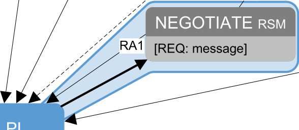
definition for autonomous vehicles. In the following can be reused without a thorough understanding of
sections, we will introduce and explain the framework the inner workings once its behaviours and outcomes
in a bottom-up fashion.                                  are defined. We will discuss this separation and de-
                                                         coupling extensively in the Reactive State Machine
                                                         (RSM) and the Proactive Manoeuvring Engine (PME)
4.2 Action Primitives                                    sections. The controlling sub-manoeuvre is denoted
The lowest layer of the framework is composed of ac-     with   PME while the reactive ones are marked with
tion primitives which are actions that directly affect   RSM    (as in Figure 5).
the physical or logical state of a vehicle. We differ-      To  fulfil  the goal of Stability, sub-manoeuvres must
entiate between physical primitives, state primitives,   be designed     such that any possible scenario (success or
and other primitives. The physical primitives are the    abort)   leads   to a defined outcome for every participat-
direct interface to the regulation layer and affect the  ing vehicle.    Therefore,    if one vehicle encounters a situ-
physical state of a vehicle, i.e, the vehicle’s position ation  that   will prevent   the  successful completion of the
or speed. State primitives affect the role of the vehi-  sub-manoeuvre         and causes   an abort-result, V2V com-
cle, i.e. whether it acts as a platoon leader or platoon munication      (or   time-outs)   must cause all other sub-
follower. They are needed to transition a vehicle from   state  machines      to terminate    at the same abort-result.
and to different idle states (e.g., at the end of a ma-  Due   to  a shared     understanding    of the sub-manoeuvre
noeuvre or when the vehicle needs to wait for instruc-   among    all  vehicles,  every   vehicle is informed about the
tions from another vehicle). Lastly, other primitives    final state   of  all  participants.
are needed to either send messages, update platoon
information, or wait for certain events. Primitives
should be designed in an orthogonal fashion, meaning
that one primitive cannot be expressed by a combi-
nation of any other primitives. Table 2 provides an
overview of action primitives that could be found in
the state-of-the-art manoeuvre descriptions.
   As the SEAD framework describes all actions on the
platooning layer, the physical primitives provide di-
rections to the low-level control of the vehicle instead
of controlling the longitudinal dynamics directly. For
instance, instead of setting the desired speed or accel-
eration of the vehicle, the primitives set the desired
location. The path-following logic on the Regulation
Layer will convert the target location into actionable Figure 6: Sub-manoeuvre description and encapsula-
commands (accelerate, decelerate, steer left / right) tion for GAPCLOSE.
for the physical layer.
                                                                  Figure 6 illustrates an example sub-manoeuvre
                                                               where a platoon leader orders another vehicle in the
4.3    Formulating Sub-Manoeuvres                              platoon to close the gap. For stability reasons, the
With the list of idle states and action primitives, we         vehicle that closes the gap is a temporary platoon
can now create sub-manoeuvres. A sub-manoeuvre en-             leader, so that when the sub-manoeuvre fails, it will
capsulates reusable behavioural patterns that involve          be the platoon leader of all other vehicles behind. The
two or more vehicles and transitions at least one of           sub-manoeuvre includes two participants, the platoon
the participating vehicles from one idle state into an-        leader (PL, vehicle A) and the temporary platoon
other. For each participating vehicle, the behaviour is        leader (TPL, vehicle B). The sub-manoeuvre can con-
described through a sequence of primitives which con-          clude in either Success (RS) or Abort 1 (RA1).
stitute a sub-state machine. Sub-manoeuvres must de-              A initiates the sub-manoeuvre through command-
sign action-communication patterns with the smallest           ing B to close the gap by sending an ORD GAP-
reasonable scope to promote re-usability and therefore         CLOSE message (A1) via V2V communication. Af-
achieve the goal of Flexibility.                               ter sending the message, A waits for the completion
   To implement the principle of Decoupling, each sub-         (A2). The message triggers B to execute the GAP-
manoeuvre is split into two or more sub-state ma-              CLOSE sub-manoeuvre (B1). B sets its headway
chines, one for each vehicle participating. As SEAD            to the requested intra-platoon distance and the reg-
follows the master-slave paradigm, one sub-state ma-           ulation layer starts to decrease the distance until it
chine controls the sub-manoeuvre (executed by the              reaches the desired headway (B2).
platoon leader), the other sub-state machines purely              In the success scenario, the desired headway is
react. The sub-state machines are connected and syn-           reached, B signals the completion of closing the gap to
chronised through V2V messages. This structure pro-            the PL through sending a DN_GAPCLOSE (B3) and
motes the goal of Simplicity through the principles of         transitions into the stable PF Idle State (B4). This
Encapsulation and Abstraction: Any sub-manoeuvre               concludes the sub-manoeuvre for B with a success-

                                                           8
Table 2: List of Action Primitives derived and condensed from the state of the art.
Acronym Primitive Parameters Description Actor
Physical Primitives
MTP Move to position TR: Target object, RO: Relative offset Move to a position defined by a relative offset to a target (vehicle) and align speed FV, PL, TPL
SH Set headway TH: Time headway or SH: Space headway Set the desired time or space ahead to preceding vehicle and adjust real distance PF, TPL
State Primitives
BFV Become free vehicle Transitions the vehicle into a Free Vehicle All but FV
BPL Become platoon leader Transitions the vehicle into a Platoon Leader All but PL
BPF Become platoon follower Transitions vehicle into a Platoon Follower All but PF
BTL Become temporary leader Transitions the vehicle into a Temporary Leader All but TPL
SW Set Wait Sets idling state to corresponding waiting state FV, PL, PF
USW Unset Wait Sets waiting state to corresponding idling state WFV, WPL, WPF
Other Primitives
W Wait E: Event to wait for, TO: Timeout Waits for an event to occur, a message, or for a timeout All
SND Send Message M: Message, R: Receiver Sends a message to the receiver All
UPI Update platoon information Updates information about the platoon (number and order of followers etc.) PL
*(W)FV: (Waiting) Free vehicle, (W)PF: (Waiting) Platoon Follower, (W)PL: (Waiting) Platoon Leader, TPL: Temporary Platoon Leader
result RS (B5). A receives the message and concludes of the JOIN TAIL manoeuvre as it was also described
the sub-manoeuvre with a success-result RS (A3). in Figure 2.
In the abort scenario, if closing the gap is taking
too long, a timeout in A aborts the sub-manoeuvre.
The timeout causes A to send an ABT message to
B (A4) and to update the platoon information (A5).
Afterwards, the sub-manoeuvres concludes for A with
an abort-result RA1 (A6). B receives the message
Figure 7: Description of the JOIN TAIL manoeuvre
and will initiate the sequence to split from the original
according to the PME logic.
platoon by transitioning into a PL (B6). Once B is a
PL, the sub-manoeuvre also concludes for B with an
abort-result A1 (B7). In this illustration, the chain of sub-manoeuvres de-
The upper part (the pro-active part) and the lower scribes the entire manoeuvre. The blue lower part of
part (the reactive part) of the sub-manoeuvre is encap- the sub-manoeuvre boxes specifies the participating
sulated into two reusable blocks (A7 and B8, respec- vehicles according to the notation in Table 2 whereas
tively). These buildings blocks can then be used to vehicle A (VA) is not specified since it is always part
build manoeuvres for the Proactive Manoeuvring En- of the manoeuvre as the PL, and vehicle B (VB) is the
gine (PME) and the Reactive State Machine (RSM). participating vehicle. The JOIN TAIL manoeuvre re-
Due to the structure of the sub-manoeuvres, the ini- quires no additional actions in case of an abort and
tiation of a PME part will always leads to initiation will conclude in a stable state achieved through the
of the RSM part as well. This principle allows defin- abort-architecture within the sub-manoeuvres. More
ing manoeuvres from the perspective of the platoon elaborate manoeuvres such as the JOIN MIDDLE re-
leader without the need to describe the participant’s quire more sophisticated abort structures (e.g., a GAP
behaviour. In the same fashion as in Figure 6, it is pos- CLOSE for a platoon follower if the joining vehicle was
sible to define a comprehensive set of sub-manoeuvres unable to lane change into the platoon). This is nec-
that allows assembling complex manoeuvres with lim- essary to ensure that no vehicle will be in an unstable
ited number of restrictions. We have created an online idle state once the manoeuvre is finished.
repository where we have made graphical depictions of Defining manoeuvres in this fashion largely pro-
manoeuvres and sub manoeuvres as well as their ma- motes Simplicity as a manoeuvre can be described
chine readable descriptions (see Section Section 4.8) from the leader’s point of view while the reactive part
publicly available 1 . of all sub manoeuvres (also referred to as the universal
RSM) takes care of the participating vehicles’ perspec-
tive.
4.4 Formulating Manoeuvres
To promote the design goal of Simplicity and due to 4.4.1 Simultaneous Manoeuvres
the master-slave paradigm of SEAD, a manoeuvre
Manoeuvres with two or more participating vehicles
only needs to be described from the perspective of
can potentially benefit from the parallel execution of
the platoon leader. The behaviour of the other partic-
sub-manoeuvres. To facilitate this, the SEAD frame-
ipants is defined in the sub-manoeuvres and the initi-
work introduces a wrapper for the simultaneous exe-
ation of these sub-manoeuvres is done by the platoon
cution, referred to as the SIM WRAPPER. This con-
leader via V2V messages. A sequential manoeuvre
struct can involve an arbitrary number of simultane-
(see Section 4.4.1 how to define simultaneous manoeu-
ous sub-manoeuvres whereas every sub-manoeuvres’
vres) is a chain of sub-manoeuvres, where the transi-
controlling part (the upper part in Figure 6) is exe-
tion to the next sub-manoeuvre depends on the result
cuted by the same leader and the reactive portion (the
of the previous one. Figure 7 shows the formulation
lower part in the same figure) is executed by the partic-
1 The library can be found at https://github.com/sead- ipants. Two simultaneous sub-manoeuvres, however,
framework/manoeuvre-catalogue cannot involve the same participating vehicle.
9To comply with the requirement that a state ma- 4.6 Reactive State Machine (RSM)
chine can only be in one state, the SIM WRAPPER
can be understood as a product state machine of the The combination of all idle superstates into one big
controlling portions of all involved sub-manoeuvres. interconnected state-machine yields the so-called Re-
Since the reactive portion is executed in separate ve- active State Machine (RSM), which can be seen as a
hicles through the Decoupling principle, they occur complete behaviour definition for all platooning vehi-
in separated state machines in distinct systems. The cles except the platoon leader. As the platoon leader
execution result can be any element from the Carte- coordinates and controls the manoeuvres, this state-
sian product of all execution result sets from all sub- machine is called reactive as it reacts to what the
manoeuvres. leader is doing. Figure Figure 9 shows the complete
RSM for a platooning system which supports a num-
ber of basic sub manoeuvres. For better readability,
4.5 Idle States and Super-States we chose sub manoeuvres as the abstraction level in
this illustration, however, each of the sub manoeuvre
With the definition of idle states and sub-manoeuvres, boxes could be replaced by the entire sub manoeuvre
it is possible to define them together to derive a state- definition (e.g., Figure 6.
machine on an abstraction level that clearly shows The RSM describes the universal reactive behaviour
how the vehicle can transition from one idle state to of any vehicle for any manoeuvre that can be built us-
another via which sub-manoeuvre. We combine the ing sub-manoeuvres as building blocks. However, the
idle state and its associated sub-manoeuvres (i.e., the RSM describes only the decoupled reactive behaviour
sub-manoeuvres that a vehicle can execute if it is in (as indicated by the RSM in any sub-manoeuvre box).
the idle state upon reception of a V2V message) into It does not implement how the manoeuvre is logi-
an idle super-state. This concept is shown in Figure 8, cally performed, i.e. the sequence of sub-manoeuvres
where the idle state WFV (Waiting Free Vehicle) and comprising a manoeuvre. This implements the first
three sub-manoeuvres LC_BPF (Lane Change & Be- half of the Decoupling principle. The second half of
come Platoon Follower), MOVETOPOS (Move to Po- Decoupling, the formulation and control of manoeu-
sition), and ATTACH are all combined into a super- vres, is implemented by a complementary structure
state. This superstate can only be left through the suc- that steers manoeuvres, namely the Proactive Ma-
cessful or unsuccessful execution of sub-manoeuvres or noeuvring Engine (PME).
when a time-out occurs.
The introduction of the RSM strongly promotes the
Every stable Idle State (FV, PF, PL) has an idling goal of Stability. As can be seen in Figure 9, the RSM
superstate. Within this superstate, the idle state will defines the behaviour in case of an abort for every sub-
be referred to as a LLI (Link Layer Interface) idle manoeuvre. This structure, thus, always brings the
state, because in these states, the vehicle can make vehicle to a defined state in whichever way a manoeu-
(or receive) high-level decisions to carry out collabora- vre terminates. According to the Abstraction princi-
tive actions, for instance, joining or leaving a platoon, ple, the RSM reuses sub-manoeuvres, which leads to
the decisions for which are made in the Link Layer. all building blocks in the RSM being on an equivalent
When the vehicle is in an unstable idle state (i.e., conceptual level. This directly mitigates the two key
WFV, WPF, WPL, TPL), thus in a manoeuvre, the shortcomings of varying conceptual depth and repet-
LLI is inactive because manoeuvre initiation is only itive patterns. Since the structure and design of the
possible when the vehicle is not already performing a sub-manoeuvres is aligned with the goal of Flexibility,
manoeuvre. Since this paper focuses on the Platoon the RSM introduces no further restrictions regarding
Layer and the LLI models the Link Layer, the inner this concern.
workings of the LLI will not be covered here.
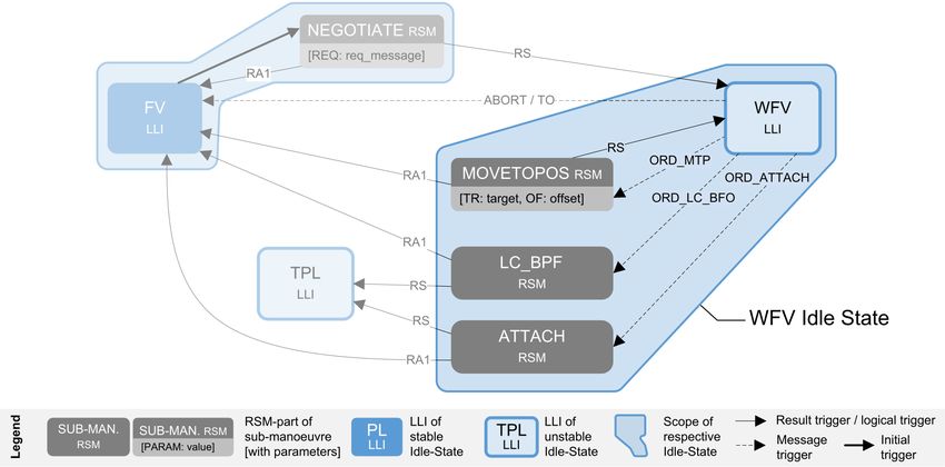
4.7 Proactive Manoeuvring Engine
(PME)
While both proactive and reactive behaviour defini-
tions can be combined into one state-machine, we
separate them for the sake of Simplicity and Decou-
pling. To this end, the Proactive Manoeuvring En-
gine (PME) complements the reactive behaviour of
the RSM (as can be seen in the left bottom of Figure 9
they are indeed connected). The PME is therefore an
extension to the PL’s RSM behaviour and is respon-
Figure 8: Definition of the WFV Idle Superstate. It sible for the coordination of platooning manoeuvres.
contains the WFV LLI Idle state as well as the sub- Figure 10 shows the PL LLI with the connection
manoeuvres that can be performed by the WFV to to the RSM part (Figure 9) on the right side and
transition into another Idle State. the entire PME on the left side. The level of ab-
straction chosen in this figure is on the manoeuvre
10Figure 9: Reactive State Machine (RSM). It describes the reactive behaviour by combining all sub-
manoeuvres.
layer with the example at hand supporting the JOIN, sub-manoeuvre where the PL requests an FV to join,
LEAVE and SPLIT manoeuvres. These manoeuvre the SEAD framework can also adapt to this paradigm.
boxes could be extended to their respective contained
sub-manoeuvres (or even further to include the entire
4.8 Manoeuvre Design Language
controlling part of each sub-manoeuvre), however, Ab-
straction and Decoupling allow us to illustrate the pla- Although the visual description of manoeuvres and
tooning system in a more comprehensible way. The sub-manoeuvres is easily comprehensible for humans,
PME combines the manoeuvre schemes of all manoeu- machines will not be able to process it. To allow flexi-
vres and steers the manoeuvres from the perspective bly redesigning manoeuvres and sub-manoeuvres, we
of the PL. Manoeuvres are initiated through the LLI have developed a Manoeuvre Design Language (MDL)
of the PL either directly (direct init. in Figure 10) that directly translates from and into a graphical rep-
or through a request REQ that triggers a NEGOTI- resentation. In the future, a graphical editor to cre-
ATE sub-manoeuvre. When adding a new manoeuvre, ate and export manoeuvres and sub-manoeuvres as
rules in the LLI must define when it will be called (i.e. JSON MDL files will help to easily design manoeuvres
which REQ message evokes a NEGOTIATE or which graphically and to directly feed them into simulation
conditions triggers a direct init.) as illustrated in Fig- systems. The simulation system parses the MDL file
ure 10. and generates the code required for the execution of
Only manoeuvres that concern exclusively platoon manoeuvres according to the SEAD framework. The
followers can be instantiated directly by the PL. For MDL is based on JSON and was inspired by the syn-
instance, a PL cannot command an FV to join its tax and structure of the Amazon States Language [].
platoon without a prior request of the FV to join. One JSON MDL file has a unique ID (or action ID)
This idea imposes that joining is always initiated and describes a (sub-)manoeuvre following a fixed syn-
through an FV. However, by designing an additional tax. The syntax of the language is outside of the scope
11Figure 10: Proactive Manoeuvring Engine (PME). A manoeuvre can either be initiated through an acknowl-
edged request through NEGOTIATE or directly through the LLI of the PL.
of this paper but can be accessed in [33] Improving and Extending the SEAD Frame-
work
Once the required simulation tools for platooning
5 Conclusion and Future Work in urban environments are in place, further building
blocks may be designed extending the SEAD frame-
This paper introduces the SEAD framework that sim-
work. The framework will allow formulating complex
plifies the formulation of manoeuvres for vehicle pla-
urban manoeuvres such as LEAVE MIDDLE AND
tooning. It is based on the four principles of Stan-
TURN LEFT (or LMTL), yet the further develop-
dardisation, Encapsulation, Abstraction and Decou-
ment of primitives, sub-manoeuvres, and communica-
pling (SEAD). As previous research has shown [1],
tion patterns will be required.
vehicle platooning has the potential to substantially
increase road capacity and traffic throughput, provid- To increase the adoptability and usability of the
ing a potential solution for traffic systems to adapt to SEAD framework, future research could focus on de-
the ever-increasing traffic demand. Although vehicle veloping a stand-alone application-agnostic tool that
platooning is a promising concept, it remains challeng- models the Platoon Layer according to the presented
ing to define and describe collaborative manoeuvres. framework. However, since the Platoon Layer and the
This poses a bottleneck in the development pace of Regulation Layer are closely interconnected through
the platooning concept and hampers its applicability the Action Primitives, an elaborate communication
in real-world scenarios. interface between these two layers needs to be de-
The design of the SEAD framework was conceptu- veloped to allow for modularisation. The resulting
alised to resolve four key shortcomings of the state- module could then be optimised in simulations and,
of-the-art description of manoeuvres using coupled in the further future, be deployed within the vehicle
state machines: First, as a manoeuvre description con- software.
sists of one state machine per participant, the reader Furthermore, although the proposed framework
must synchronise the state machines to understand allows defining elaborate abort structures for ma-
the manoeuvre. Second, the investigated schemas re- noeuvres and sub-manoeuvres, it does not propose
veal varying conceptual depth within and among ma- an abort-and-retry structure. Once elaborate mod-
noeuvre description as well as, third, differing verbal els are in place to evaluate if a second attempt
descriptions of equivalent components. This hetero- could be successful, higher-order manoeuvres and re-
geneity makes it difficult to understand and compare modularisation of certain sequential parts of a ma-
manoeuvres. Finally, various action-communication noeuvre provide the opportunity to implement such
patterns surfaced in multiple manoeuvre descriptions, abort-and-retry structures.
making them seem more complex than they are. Empowering Further Studies
The SEAD framework is a first step to formalise As mentioned before, the biggest advantage of
the Platoon Layer of an Automated Highway System. the SEAD framework is its capability of design-
It provides the means to conduct further research on ing manoeuvre variants and alternatives through re-
the performance of manoeuvre variations, alternatives arranging the sub-manoeuvres once all building blocks
and platoon forming strategies. There are two main are implemented and the RSM defined all required
future research fields involving the proposed frame- state transitions. This allows for various dynamic in-
work. vestigations.
12For instance, traffic simulators implementing the [5] M. Amoozadeh, H. Deng, C.-N. Chuah, H. M.
framework such as BEHAVE [34] could provide a Zhang, and D. Ghosal, “Platoon management
means to identify the most efficient alternative of a with cooperative adaptive cruise control enabled
manoeuvre through simulating all possible alterna- by vanet,” Vehicular communications, vol. 2,
tives and measuring the execution time, success rate, no. 2, pp. 110–123, 2015.
and traffic flow influence of the alternatives. Using
the same approach, different platoon formation strate- [6] A. Hsu, S. Sachs, F. Eskafi, and P. Varaiya, “The
gies (Weakest-in-Front, Last-in-at-Tail, dynamic con- design of platoon maneuvers for ivhs,” in 1991
textual strategies etc.) could be investigated regard- American Control Conference. IEEE, 1991, pp.
ing their influence on the overall traffic flow. The 2545–2550.
SEAD architecture has already been implemented and [7] R. Rajamani, H.-S. Tan, B. K. Law, and W.-B.
is a critical part of the Autonomous Vehicle Driver Zhang, “Demonstration of integrated longitudi-
Model architecture described in [35]. nal and lateral control for the operation of auto-
The proposed framework utilises a timeout-strategy mated vehicles in platoons,” IEEE Transactions
so that manoeuvres are not leading into a deadlock if, on Control Systems Technology, vol. 8, no. 4, pp.
for instance, a human-driven vehicle is blocking the 695–708, 2000.
way to complete a manoeuvre. The timeout-strategy,
however, is a mechanism to ensure deadlock-freeness. [8] E. M. Clarke and R. P. Kurshan, “Computer-
Research may investigate further models to identify aided verification,” IEEE Spectrum, vol. 33, no. 6,
blocking situations with a low likelihood of manoeuvre pp. 61–67, 1996.
success to interrupt the manoeuvre using as a trigger
an event rather than a time-out. Otherwise, simula- [9] H. H. Bengtsson, L. Chen, A. Voronov, and
tions may allow to numerically optimise the time-out C. Englund, “Interaction protocol for highway
parameters with, for instance, the overall traffic flow platoon merge,” in 2015 IEEE 18th Interna-
as the objective variable to maximise. tional Conference on Intelligent Transportation
After all, platoon manoeuvring is a powerful yet Systems. IEEE, 2015, pp. 1971–1976.
complex technique to fulfil the ever-increasing traffic [10] M. Segata, B. Bloessl, S. Joerer, F. Dressler, and
demand with the given capacities we have. Further R. L. Cigno, “Supporting platooning maneuvers
research will have to investigate many more gaps and through ivc: An initial protocol analysis for the
find the most effective strategies to maximise traffic join maneuver,” in 2014 11th Annual conference
throughput. To unlock the full potential of platoon- on wireless on-demand network systems and ser-
ing, the SEAD framework aims to pave the way for vices (WONS). IEEE, 2014, pp. 130–137.
this future research by providing a formalisation of the
platooning logic and simplifying the way how new ma- [11] X.-Y. Lu and J. K. Hedrick, “Longitudinal con-
noeuvres are created and existing ones are compared trol algorithm for automated vehicle merging,”
and optimised. International Journal of Control, vol. 76, no. 2,
pp. 193–202, 2003.
References [12] X.-Y. Lu, H.-S. Tan, S. E. Shladover, and J. K.
Hedrick, “Automated vehicle merging maneuver
[1] P. Varaiya, “Smart cars on smart roads: prob- implementation for ahs,” Vehicle System Dynam-
lems of control,” IEEE Transactions on auto- ics, vol. 41, no. 2, pp. 85–107, 2004.
matic control, vol. 38, no. 2, pp. 195–207, 1993.
[13] C. Nowakowski, D. Thompson, S. E. Shladover,
[2] D. N. Godbole, F. Eskafi, E. Singh, and A. Kailas, and X.-Y. Lu, “Operational concepts
P. Varaiya, “Design of entry and exit maneuvers for truck maneuvers with cooperative adaptive
for ivhs,” in Proceedings of 1995 American Con- cruise control,” Transportation Research Record,
trol Conference-ACC’95, vol. 5. IEEE, 1995, pp. vol. 2559, no. 1, pp. 57–64, 2016.
3576–3580.
[14] H.-H. Hsu and A. Liu, “Platoon lane change
[3] A. Hsu, F. Eskafi, S. Sachs, and P. Varaiya, “Pro- maneuvers for automated highway systems,” in
tocol design for an automated highway system,” IEEE Conference on Robotics, Automation and
Discrete Event Dynamic Systems, vol. 2, no. 3-4, Mechatronics, 2004., vol. 2. IEEE, 2004, pp.
pp. 183–206, 1993. 780–785.
[4] J. Ivanchev, D. Zehe, V. Viswanathan, S. Nair, [15] H. C.-H. Hsu and A. Liu, “Kinematic design for
and A. Knoll, “Bisos: Backwards incremental sys- platoon-lane-change maneuvers,” IEEE Trans-
tem optimum search algorithm for fast socially actions on Intelligent Transportation Systems,
optimal traffic assignment,” in 2016 IEEE 19th vol. 9, no. 1, pp. 185–190, 2008.
International Conference on Intelligent Trans-
portation Systems (ITSC). IEEE, 2016, pp. [16] E. S. Kazerooni and J. Ploeg, “Interaction proto-
2137–2142. cols for cooperative merging and lane reduction
13You can also read