A Systematic Review of Perception System and Simulators for Autonomous Vehicles Research - MDPI
←
→
Page content transcription
If your browser does not render page correctly, please read the page content below
Review
A Systematic Review of Perception System and
Simulators for Autonomous Vehicles Research
Francisca Rosique 1,*, Pedro J. Navarro 1,*, Carlos Fernández 1 and Antonio Padilla 1
División de Sistemas e Ingeniería Electrónica (DSIE), Universidad Politécnica de Cartagena, Campus Muralla
del Mar, s/n, 30202 Cartagena, Spain; carlos.fernandez@upct.es (C.F.); antonio.padilla@upct.es (A.P.)
 * Correspondence: paqui.rosique@upct.es (F.R.); pedroj.navarro@upct.es (P.J.N.); Tel.: +34-968-32-6589 (F.R.)

 Received: 30 November 2018; Accepted: 31 January 2019; Published: 5 February 2019

 Abstract: This paper presents a systematic review of the perception systems and simulators for
 autonomous vehicles (AV). This work has been divided into three parts. In the first part, perception
 systems are categorized as environment perception systems and positioning estimation systems.
 The paper presents the physical fundamentals, principle functioning, and electromagnetic spectrum
 used to operate the most common sensors used in perception systems (ultrasonic, RADAR, LiDAR,
 cameras, IMU, GNSS, RTK, etc.). Furthermore, their strengths and weaknesses are shown, and the
 quantification of their features using spider charts will allow proper selection of different sensors
 depending on 11 features. In the second part, the main elements to be taken into account in the
 simulation of a perception system of an AV are presented. For this purpose, the paper describes
 simulators for model-based development, the main game engines that can be used for simulation,
 simulators from the robotics field, and lastly simulators used specifically for AV. Finally, the current
 state of regulations that are being applied in different countries around the world on issues
 concerning the implementation of autonomous vehicles is presented.

 Keywords: autonomous vehicle; perception system; simulator; LiDAR; model based design

1. Introduction
      Rapid advances in electronics, information, and communications technology (leading to
miniaturization and improvement of computers, sensors and networking performance) have given
rise to the development of several autonomous vehicles (AV) technologies [1]. UCSUSA [2] defines
autonomous vehicles as follows: “Self-driving vehicles as cars or trucks in which human drivers are
never required to take control to safely operate the vehicle. Also known as autonomous or
“driverless” cars, they combine sensors and software to control, navigate, and drive the vehicle.” For
Thrun [3], an AV is “an unmanned vehicle that is capable of sensing its environment and navigating
without human input”. However, the standard way to discuss autonomous vehicles is to talk about
“self-driving levels”, as defined by the SAE (Society of Automotive Engineers) [4]. The SAE, which is
an automobile standardization agency, divided the autonomous driving capacity of a vehicle into six
levels, from the most basic systems to 100% autonomous driving. These levels help measure how
advanced the technology of a certain autonomous car is. This has opened up numerous fields of
research and development that, although end up being interconnected, correspond to very diverse
areas.
      In parallel to this evolution, the processes and procedures (function requirements and
regulations) established for testing AV functions have also been developed and established over the
previous decades. There, however, are concerns regarding the possible consequences of such a
technology, especially with regard to peoples’ safety, mechanical failures that may cause crash and
the costs of such an incident. To guarantee that an AV is safe and to reduce costs, different scenarios
must be modelled and tested. Systematic testing of autonomous vehicles can be performed in

Sensors 2019, 19, 648; doi:10.3390/s19030648                                      www.mdpi.com/journal/sensors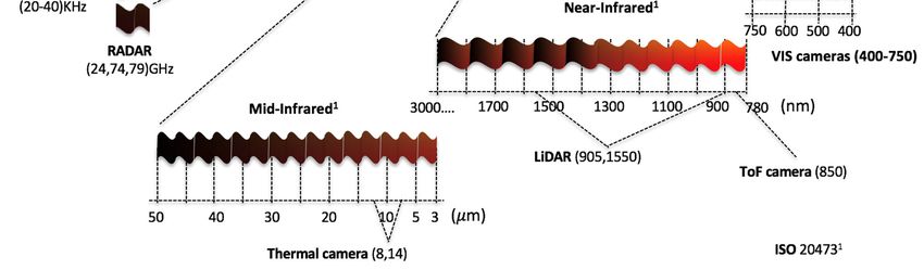
Sensors 2019, 19, 648                                                                             2 of 29

simulation or in the physical world. Physical tests offer real testing scenarios, and engineers can use
actual vehicles instead of models. However, regulations restrict the use of these vehicles in cities;
thus, to perform tests with real AVs, one needs access to expensive hardware and field tests, which
consume a considerable amount of time. According to recently published reports [5,6], it is impossible
to perform empirical field tests that verify the safety of autonomous cars in a reasonable timeframe.
In this context, simulation, modelling and testing has the potential to fill the gap and enable rigorous,
controlled, and timely evaluation AV systems.
       The research community recognizes three types of simulations [7]: live, virtual, and constructive
(LVC). A live simulation is simply an operational test, with sensors used to identify which systems
have been damaged by simulated firings, using real forces and real equipment. It is the closest
exercise to real use. A virtual simulation ("X-in-the-loop") might test a complete system prototype
with stimuli produced either by a computer or otherwise artificially generated. This sort of exercise
is typical of a developmental test. A constructive simulation is a computer-only representation of a
system or systems. Therefore, a simulation can vary from operational tests to a fully computer-
generated representation (i.e., no system components involved) of how a system will react to multiple
inputs. It can be used for several purposes: (1) The design and evaluation of operational and
development tests; (2) simulation, taking into account the levels of system aggregation, modeling
level of the individual components of a system (for example, the system software), or modeling level
of the system as a whole—to model a complete prototype and model multiple system interactions
(i.e. a RADAR component with the rest of the system).
       However, as is exposed in [8], the first thing that must be taken into account is the type of
characteristics or systems that can be tested through simulation (see Figure 1). In this work, we focus
on the perception of autonomous vehicles as offering greater autonomy and complexity, emphasizing
on their subsystems [9]: Environmental perception, and localization.

                              Figure 1. Typical autonomous vehicle system.

     In this paper, we present a systematic literature review on simulators applied to system
perception in autonomous vehicles. For this, the technological and legacy aspects involved in the
development of AVs are presented in detail, specifying the different alternatives available to simulate
and test each of the subsystems.
     The paper is organized as follows: Section 2 and 3 detail the technologies habitually engaged to
capture information from the environment and to estimate position of the autonomous vehicles.
Section 4 discusses the current fusion technics used to combined information from the perception
systems. Section 5 carries out an exhaustive collection of tools and platforms capable of performing
simulation tasks in the AV ambit. Section 6 shows the current state of legislation with regard to the
legal aspects of autonomous driving and testing possibilities of AV in different countries. Section 7
presents our conclusions.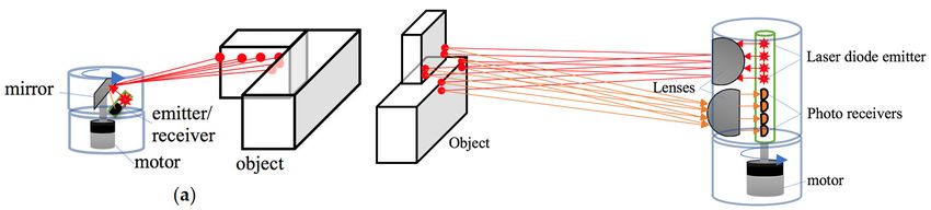
Sensors 2019, 19, 648 3 of 29
2. Environment Perception System
An autonomous vehicle acquires knowledge of its surrounding in two stages. The first stage
consists of scanning the road ahead to detect possible changes in driving conditions (traffic lights and
signs, pedestrian crossing, and barriers, among others). The second stage relates to the perception of
other vehicles.
This section presents the most representative sensors that make up the perception systems of
AVs: Ultrasonic, RADAR, LiDAR, cameras, IMU, GNSS, and RTK. There are numerous informative
and scientific articles or books that show the types of sensors used in AVs, their applications, as well
as their advantages and disadvantages. These works portray the sensors as black boxes, formed by a
set of inputs and outputs, without delving into the physical foundations of their operation. As a novel
aspect of this work, these sensors are presented from a point of view of the electromagnetic spectrum
that they actively or passively use for their operation. This will allow researchers to acquire a deeper
knowledge of the benefits and disadvantages of these sensors in degraded environments or adverse
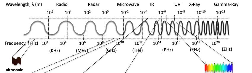
weather conditions. In Figure 2, the electromagnetic spectrum is divided into two scales:
Wavelengths and frequencies. In addition, the spectral ranges used by the sensors analysed in this
work are shown.
Figure 2. An overview of different spectra used for perception systems in autonomous vehicles.
2.1. Ultrasonic Sensor
As its name indicates, ultrasonic sensors use sonic waves, in the range of 20 kHz to
40 kHz, generated by a magnetoresistive membrane, to measure the distance to an object. Its principle
of operation is based on the measurement of the time of flight (ToF) of the sonic wave from when it
is emitted until the echo is received:
= × ToF (1)
2
The c velocity of the wave is in meters per second and ToF is time of flight in seconds.
These sensors are usually used in industrial environments for the measurement of height in
storage of all types of raw materials. In vehicles, they are used in parking systems or as short distance
measurement sensors at low speeds (Figure 3a and b). These low-cost sensors produce good results
when measuring distances with any material, independent of its colour, in dusty environments or in
adverse weather conditions (humidity or rain). Disadvantages of these sensors include a tendency to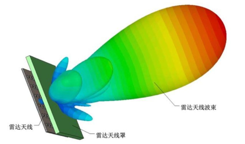
Sensors 2019, 19, 648                                                                                       4 of 29

produce false positives by bouncing, and a blind zone (blanking) in the measurements, located
between the sender element of the sensor and the minimum range.

                                                                                (b)
                        (a)

           Figure 3. (a) Ultrasonic car sensors from Bosch; (b) an assistance parking system from Audi.

2.2. RADAR (Radio Detection and Ranging)
      Radar systems work in wavelengths of the order of millimetres; these are used in a wide variety
of military and civil applications, such as aerial or terrestrial threat detection systems, shooting
systems, and airports or meteorological systems. The emergence of smart vehicles and the need to
increase road safety have triggered the use of this type of device in the automotive sector. Radar
systems for intelligent vehicles work at frequencies of 24/77/79 GHz, known as millimetre wave radar
(MMW). The radar measures the distance between the emitter and the object by calculating the time
of flight of the emitted signal and the received echo. The radars not only allow the detection of the
distance to several targets, but are also capable of accurately supplying the direction and speed of the
targets. The new radars for vehicles use an array of micro antennas capable of generating a set of
lobes that allow improvement of the range and a processing system for the detection of multiple
targets (Figure 4a and b).

                                                                                                main lobe

                                           microarray antenna
                                                                          insolate material

                        (a)                                                     (b)

      Figure 4. Millimetre-wave RADAR CAR70 from Nanoradar: (a) Microarray radar antenna;
      (b) multi-lobe system.

      Range millimetre-wave RADAR is applied in Blind Spot Detection (BSD), Lane Change Assistant
(LCA), Rear Cross Traffic Alert (RCTA), Forward Cross Traffic Alert (FCTA) or radar video fusion.
Radar waves have higher penetrability because they offer good features in all weather conditions,
and can accurately detect short-range targets in front, to the side, and to the rear side of vehicle. For
this reason, they are used in several ADAS systems. RADAR can significantly improve vehicle safety
performance and reduce the decision-making burden of people at the wheel. Furthermore, it can be
installed besides the bumpers of the vehicle. Some disadvantages of this sensor type are the lack of
precision, its reduced Field of View (FOV), and the fact that it can produce false positives due to
bouncing of the emitted signal.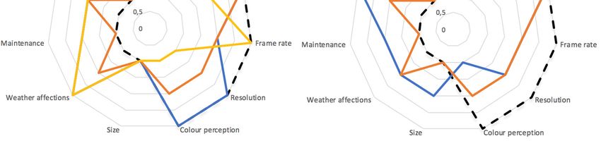
Sensors 2019, 19, 648                                                                                   5 of 29

2.3. LiDAR (Light Detection and Ranging)
     LiDAR systems were initially developed in the 70s to measure elements in sea or land from
satellites or airplanes. It was specifically developed for the detection of submarines by the American
Navy. LiDAR systems base their operation on the measurement of the time of flight of a pulsed light
emitted from a laser diode until it is received by an emitter. The emission are in infrared ranges (905
nm or 1550 nm). Emissions at 905 nm require less energy than those emitted at 1550 nm because the
water in the atmosphere begins to absorb energy from 1400 nm. This initial disadvantage of power
increase at 1550 nm is used by the aqueous liquid of the eye to totally filter this wavelength, making
them less harmful than LiDAR at 905 nm [10]. Lasers used for vehicles belong to Class 1 [11] and are
safe under all conditions of normal use. LiDARs use the ToF principle to carry out the measurement
of distance between emission and reception. These can be classified according to the type of
information they obtain from their environment in 2D or 3D LiDARs or it can be classified according
to their construction rotary or solid state LiDAR. 2D LiDAR obtains information from the
environment by projecting a single laser beam on a rotating mirror perpendicular to the axis of
rotation (see Figure 5a). The 3D LiDAR allows to obtain a 3D map of great accuracy to be obtained of
the environment; for that purpose, they use a set of diodes lasers mounted on a pod that rotates at
high speed (see Figure 5b). The number of lasers installed in the pod determines the accuracy of the
point cloud obtained in each turn. Currently we can find 3D LiDARs that integrate from 4 to 128
lasers or channels with a horizontal FOV of 360 grades and vertical FOV that oscillates between 20-
45 grades with accuracy of a few centimetres. Depending of the number of channels, 3D LiDAR are
used in Adaptive Cruise Control (ACC), object avoidance, object identification or 3D mapping.
LiDAR is affected by weather conditions such as rain, snow, fog or dusty environments due to the
diffraction of light in these environments. Furthermore, they reduce their operating range detection
depending on the reflectivity of the objects that are reached by the laser beams. The maximum
detection capacity depending on the type of reflectivity of the material to be detected is presented in
the datasheet provided by the manufacturer.

                        (a)
                                                                            (b)

                                                       (c)

      Figure 5. Operating schemes: (a) Rotating 2D LiDAR, (b) rotating 3D LiDAR, (c) solid state 3D LiDAR.

     The last kind of device based on laser measurement that has arrived in the autonomous vehicles
world is the solid state LiDAR. Solid state LiDAR allows a 3D representation of the scene to be
obtained around the LiDAR without the use of mobile parts in the device. A micro mirror MEMS
circuit carries out the synchronization with a beam laser to scan the horizontal FOV in multiples lines.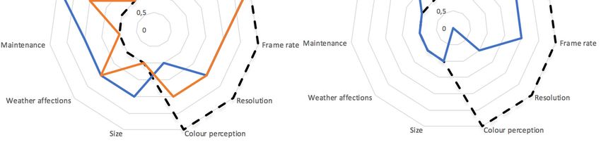
Sensors 2019, 19, 648                                                                             6 of 29

For that, the micro-mirror reflects the beam over a diffuser lens, which creates a vertical line that
touches the objects (Figure 5c). The light reflected is captured by a lens and is sent to a photodetector
array to build the first line of a 3D matrix. The process is repeated until a point cloud of the scene is
created. This feature notably increases its durability, reduces maintenance tasks, and decreases its
price. Solid state has a smaller FOV than the rotary LiDAR. The trends in perception system are
replacing the current rotating 3D LiDAR by a set of solid state LiDARs integrated around the vehicle.

2.4. Cameras
      In the perception system of autonomous vehicles and from a point of view of the wavelength
received by the device, cameras can be classified as visible (VIS) or infrared (IR). The element used
by the camera to capture a scene is known as an imaging sensor and has traditionally been
implemented with two technologies: Charge-coupled device (CCD) and complementary metal oxide
semiconductor (CMOS). CCD image sensors are manufactured by an expensive manufacturing
process that confers them unique properties such as high quantification efficiency and low noise.
CMOS was developed to reduce the cost of manufacturing at the expense of reducing its
performance. The design of the extraction architecture of the luminosity values allows the selection
and processing of regions of interest (ROI); furthermore, the CMOS device has a lower consumption
than CCDs. These characteristics make them the most used technology for mobile devices. On the
other hand, CCD technology has a high dynamic range and higher image quality in low light
environments. The differences of both technologies begin to overlap and it is expected that in the
future, CMOS technology will replace CCD [12,13].
      VIS cameras capture wavelengths between 400 nm to 780 nm (see Figure 2), same as the human
eye can. The visible spectrum is divided into three bands or channels: R, G and B, which will be coded
separately. These devices are the most commonly used in AV perception systems to obtain
information about the surroundings of the vehicle due to their low cost, high quality colour
information, and high resolution. The huge volume of data generated by means of the device
supposes a further problem for the processing system. The most common applications are BSD, side
view control, accident recording, object identification, LCA, and signs detection. VIS cameras are
highly affected by variations in lighting conditions, rain, snow or fog conditions and for this reason
are combined with RADAR and LiDAR technologies to increase its robustness.
      The combinations of two VIS cameras with a known focal distance allows stereoscopy vision to
be performed, which adds a new channel called depth information. Cameras with these features are
known as RGBD. These devices supply a 3D representation of the scene around the vehicle.
      IR cameras are passive sensors that work in infrared (IR) wavelengths ranges between 780 nm
to 1 mm. There are many devices which work in this spectrum because fewer light interferences exist
(e.g., LiDARs). Perception systems that includes IR cameras [14,15] work in near-infrared (NIR: 780
nm–3 mm) or mid-infrared (MIR: 3mm–50mm, known as thermal cameras) ranges. The uses of NIR
usually replace or complement VIS cameras. IR cameras are used: (1) In situations where there are
peaks of illumination; for example, at the exit of a tunnel, when driving in front of the sun or when
long light crosses the car; and (2) in hot body detection, such as pedestrians [16–18], animals [19] or
other vehicles [20]. In these cases, the thermal cameras allow the segmentation process to be
simplified to fewer operations based on thresholds and they are not affected by weather or lighting
conditions. On the other hand, they supply a grey scale image and the bigger cell size of the image
sensor notably reduces its resolution.
      ToF cameras are active sensors that use the time of flight principle to obtain a 3D representation
of the objects in the scene. ToF cameras emit NIR light pulses of 850 nm with an LED (Light Emitting
Diodes) array and they measure the difference in phase Δφ between the modulated signal emitted
(sE) and the signal received (sR) to compute the distance, as shown in Equation 1 and Figure 6 [21].
Sensors 2019, 19, 648                                                                                      7 of 29

                            Figure 6. Emitted signal (blue) and received signal (red).

                                                                 Δ
                                                 =       ×                                                   (2)
                                                     2       2
     The distance ranges from 10 meters for indoor scenes and about 4 meters for outdoor scenes,
depending on the number of LEDs in the matrix. As with IR cameras, they have a low resolution due
to characteristics of the wavelength they are required to capture.
     Table 1 shows a summary of the advantages and disadvantages of the sensors analysed in this
section. In the table are shown 11 features, which have been quantified in line with data obtained in
this review. The quantification has been carried out using four scores to simplify the process: 0—
none, 1—low, 2—medium and 3—high. The first six features pose maximum quality with the highest
score and the rest obtained the best quality with the minimum score.

               Table 1. Summary of the main features of sensors used in perception systems of AV.

                                 Ultrasonic     RADAR                     3D LiDAR             Cameras
                                                                     Rotating Solid State   VIS IR ToF
                FOV                   1              2                  3          2         3   3     2
               Range                  1              3                  3          3         2   3     2
              Accuracy                1              2                  3          3         3   2     2
             Frame rate               2              2                  2          2         2   3     3
             Resolution               1              1                  2          2         3   1     1
          Colour perception           0              0                  1          2         3   1     1
                Size                  1              1                  2          1         1   1     1
          Weather affections          1              1                  2          2         3   1     3
            Maintenance               2              1                  2          1         2   2     2
              Visibility              2              1                  3          2         2   2     2
                Price                 1              2                  3          1         1   3     2

     Figure 7 shows a set of spider charts of features of the sensors presented in this review. A perfect
sensor is defined as the one that obtains the best scores in all the characteristics analysed in this
review. This means maximum values (3) for FOV, range, accuracy, frame-rate, resolution, colour
perception, and minimum values (0) for weather affections, maintenance, visibility, and price. This
comparison offers a clear overview of the sensors’ strengths and weaknesses.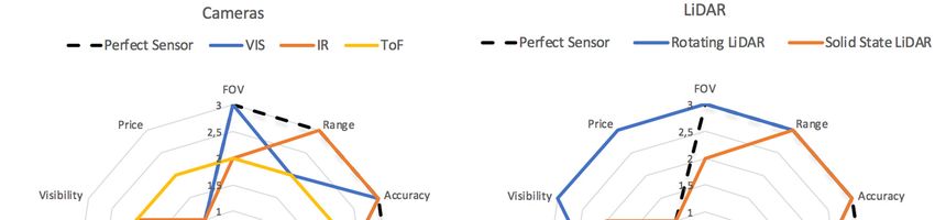
Sensors 2019, 19, 648                                                                                    8 of 29

      Figure 7. Comparison of the features of the different sensors used in environment perception systems.

3. Position Estimation Systems

3.1. Global Positioning Systems
      Global Navigation Satellite System (GNSS) is the most widely used technology for vehicle
positioning on land, sea, and air. The GNSSs provides the absolute position of a receiver with respect
to a fixed reference and consists of a set of satellites orbiting approximately 20,000 km from the earth’s
surface. These emit signals with information about the satellite, its position, orbital parameters, etc.
This system is complete with reception systems, which receive those signals and extract information
about position, speed, and exact time. The best-known GNSS system is the Global Positioning System
or GPS, developed by the USA in the 1970s, which consists of 24 satellites located in six planes
separated by 55º and with a rotation period of 11 hours and 58 minutes. Its configuration allows any
receiver located on the earth’s surface to receive signals from between 6 and 12 satellites.
      The operating principal of the GNSS is based on measuring the time of flight of the signal
emitted by the satellite and that received by the receptor. The system is able to reliably obtain details
of position and time (x, y, z, t) with a minimum of four visible satellites. Table 2 shows the
characteristics of the most widely used GNSS systems for global positioning, their constellations,
precision, coverage, period of rotation, height, and owner [22,23].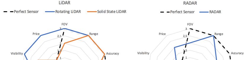
Sensors 2019, 19, 648 9 of 29
Table 2. Most commonly used global positioning systems.
GPS GLONASS GALILEO BEIDOU
Satellites 24 24 30 30 + 5*
7.8 m, civil 7.4 m, civil 1.0 m, civil 10 m, civil
Precision
5.9 m, military 4.5 m, military 0.01 m, advantage 0.1 m, military
Coverage Global Global Global Chinese
Period 11 h 58 m 11 h 15m 14 h 12h 53m
height 26650 Km 19100 Km 23222 Km 21150 Km
Owner EEUU Russia European Union China
* Geostationary Satellite.
Satellite signals are influenced by numerous errors: (1) Synchronization of the atomic clocks of
the orbiting satellites, (2) signal transmission by the ionosphere and troposphere, (3) noise in the
receivers, (4) multipath effect due to signal reflections, and (5) geometric uncertainties.
Differential GNSS (DGNSS) was developed to alleviate errors that affect signal measurement
from satellite constellations. The DGNSS consists of two GNSS receivers, a ground or base station
and a mobile station, known as a Rover. The base station knows its exact position and continuously
communicates the signal corrections to the moving station. The signal corrections provide precisions
of 0.7 m to 3 m in civil applications and improve the integrity of the measurement (ability of the
system to provide timely warnings to users when the system should not be used for navigation).
DGNSS needs a system of precisely georeferenced land stations and a communication system,
usually UHF radio, with the mobile stations.
There are other systems based on signal correction that come from satellites, such as the Satellite
Based Augmentation System (SBAS) and Real-Time Kinematic (RTK).
SBAS was designed to improve air navigation by increasing the horizontal and vertical accuracy
of the receptors and providing information about the quality of the signals. For this purpose, it
has a set of stations distributed over large geographical areas that monitor the status of the
satellite constellations, informing of any anomaly. These systems are operated by different
institutions, governments, and even private companies [24].
RTK systems use the satellite signal carrier to improve the position accuracy of the mobile
stations; the base station retransmits the carrier to one or more rover stations and these compare
the carriers with the signals received from the satellites and calculate the position accurately.
These systems obtain precisions of up to 2 cm and usually use a radio modem to communicate
between base stations and rovers within a range of 20 km. RTK has been successfully applied in
autonomous driving [25] and precision agriculture [26].
3.2. Dead-Reckoning (DR) and Inertial Positioning
DR is the process of estimating the position and heading of a vehicle based on previous position
measurements. The simplest position estimates are made using rotary sensors (encoders) fixed to the
steering wheel and the wheels of the vehicle [27], a technique known as odometry. It is not capable
of quantifying slippages or lateral movements of the vehicle, and for this reason is complemented
with Inertial Measurement Units (IMUs) which combine accelerometers, gyroscopes and
magnetometers [28]. The incorporation of these sensors allows the previously mentioned errors to be
corrected and the sampling speed of the measurement system to be increased. However, they
introduce errors due to the measurement of first and second order variables [29]. IMUs alone do not
provide a global vehicle position, so they are usually accompanied by a GNSS system.
The current positioning systems for vehicles are hybrid systems that merge data from different
sources such as odometry, IMUs, GNSS, LiDARs, RADARs and cameras to obtain a reliable position
and heading with tolerable error.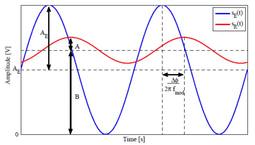
Sensors 2019, 19, 648                                                                            10 of 29

4. Fusion Algorithms
       Sensory fusion or data fusion aims to improve the measurement of two or more sources of data
from sensors, beyond the individual measurement of each of them. Sensory fusion is especially
indicated when large amounts of disparate sensor data are produced. Sensorial fusion applied to the
measurement of redundant data reduces the uncertainty of the measurement, increases the accuracy
and improves the integrity of the system, improving fault tolerance.
       Obtaining a classification of the algorithms or fusion techniques is an arduous and difficult task
due to multidisplinarity and the large number of case studies reported in the literature. In a review
carried out by [30], it is possible to find an extensive classification of fusion methods according to
different criteria such as: (1) relations between the input data sources; (2) input / output data types
and their nature; (3) abstraction level of the employed data; (4) different data fusion levels, and (5)
architecture types. In this review, we will stablish three categories: (1) estimation methods based on
Gaussian filters (e.g., Kalman filter (KF) or particle filters (PF)), (2) probabilistic inference methods
(i.e., Bayes theorem), and (3) artificial intelligence methods based on machine learning algorithms.
Three categorizations are applied to both perception systems and location systems in autonomous
vehicles. Following are examples that combine the merging of data from the different categorizations.
and different sensors of the perception and location systems.

4.1. Fusion Methods in Perception Systems
      There are numerous works related to the sensors mentioned in this review that detect vehicles,
pedestrians, lanes, signs, and so on. In [31], the data supplied by a LiDAR and a stereo camera are
fused to improve a vehicle’s detection. The method has two stages: (1) Hypothesis generation, where
a vehicle candidate is obtained, combining Haar features from depth maps with the AdaBoost
classifier; and (2) hypothesis verification, where a shape estimation of the candidates is calculated
using the LiDAR information and a support vector machine. The proposed fusion approach achieves
a lower false alarm rate in urban environments. A method that fuses the MMW RADAR with camera
information is presented in [32]. The work presents a collaborative fusion approach to achieve an
optimal balance between vehicle detection accuracy and computational efficiency. The MMW radar
first detects the potential vehicle and provides a region of interest. The vision processing module
employs symmetry detection and active contour detection to identify the vehicle inside the region of
interest provided by the MMW radar. The experimental results show a 92.36% detection rate and 0%
false alarm rate using a real-world dataset. In [33], the advantages of the fusion of LiDAR and RADAR
sensors are used in order to provide permanent precise spatial and dynamical data. The work
presents a real-time algorithm, which enables an autonomous car to comfortably follow other cars at
various speeds, while maintaining a safe distance. In [34], an unscented Kalman filter and Joint
Probabilistic Data Association is used to fuse the data from a 2D LiDAR and camera information to
detect vehicles. The presented approach achieves an increase in safety for vehicle detection in single-
lane carriage-ways, where casualties are higher than for other road classes.
      The increase in precision and robustness obtained with the fusion methods when redundant
information is available is especially relevant when the systems can produce injuries or death to
people. Pedestrian detection is a common area to use the fusion algorithms, as demonstrated by
numerous works found on this topic. In [35], the distance data and the reflexivity of a 3D LiDAR are
fused through a set of 50 features to detect pedestrians. The features are composed by three subsets:
(1) Shape features obtained in XYZ projections of pedestrian cloud points, (2) Hu invariants moments
from XYZ projections and, (3) statistical features from the reflexivity data. The data fused was used
to train an SVM. The pedestrian detection method obtained a higher classification rate when it was
compared with similar algorithms. In [36], a set of machine-learning algorithms (MLA) are tested
with different fusion schemes with the proposal of determining the best performance in pedestrian
detection. The experimental results provide a false positive rate, AUC (Area Under Curve ROC is a
metric to evaluate the performance of two classifiers), and provide an accuracy of 96.67%. An RGB
camera and a LiDAR are fused for pedestrian detection. LiDAR is used to evaluate the value of depth
perception for pedestrian detection. In the work, the detectors were trained on both input modalities
Sensors 2019, 19, 648 11 of 29
(from KITTI database) and various fusion strategies. The best performance was obtained by a late re-
scoring strategy that was designed to be sensitive to geometric context. The advance in GPUs has
allowed algorithm execution times that would have been unthinkable a few years ago (i.e., CNN);
there are numerous projects that use convolutional neural networks (CNN) to obtain high grades of
data abstraction. In [37], multispectral information is used from a thermal camera and an RGB camera
(TRGB channels) and a multi-layer fused CNN to detect pedestrians under adverse illumination
conditions. The algorithm development on the basis of a multiple-layer fusion technique can
significantly reduce the detection miss rate. In [38], the distance data with reflectance information
from 3D LiDAR is fused by means of a CNN. Distance and intensity raw data from LiDAR are
transformed to high-resolution (dense) maps, which allow direct implementation on CNNs, both as
single or multi-channel inputs. The results of the CNN were tested with the KITTI dataset Vision
Benchmark Suite [39].
4.2. Fusion Methods in Positioning Systems
The precise determination of the position of a vehicle is a crucial aspect for navigation tasks in
related areas such as autonomous vehicles, intelligent transporting systems and intelligent vehicles.
The bibliography reports a huge number of applications where fusion methods are used with sensors
belonging to both positioning systems and environment perception systems mentioned in this work.
Traditionally, the Kalman filter and extended Kalman filter has been one of the most used
algorithms to reduce the degree of uncertainty in sets of data supplied by different sources and to
increase the accuracy in positioning systems. In [40], a real-time data fusion system for improving car
positioning precision in urban environments is proposed. The proposed method uses the data from
four-wheel speed sensors and low-cost GNSS with an EKF to fuse the data. The urban scenarios are
prone to suffer low precision and transient unavailability of the GNSS signal. The main contribution
of this work enables accurate car positioning during short GNSS signal outages. In [41], a fusion
framework to obtain the cooperative positioning information from radar sensor data is presented.
The framework fuses the information received from radar sensors by means of the KF method. The
measurements recorded on a highway and a rural road demonstrate that the fusion of both
information sources outperforms the positioning estimation using only the radar sensor
In [42], a fusion method is presented, which integrates the information supplied by a stereo
camera, a 2D LiDAR, and a GPS to obtain precise positioning of a vehicle. The proposed method uses
a prelaminar stage, where an outlier-rejection invariant closest point method reduces the matching
ambiguities of scan alignment during tasks of motion estimation with the 2D LiDAR. Finally, after
the validation process, the information is fused by means of an unscented information filter.
The particle filter (PF) is a method used to obtain a good estimation of vehicle position in non-
linear models. In [43], a robust fusion algorithm is presented, based on a particle filter using the
entropy information theory. The fusion method uses a 3D urban area mapped previously (point cloud
map) together with a 3D LiDAR with 32 channels, an IMU, and wheel odometry for obtaining the
location of a vehicle in urban scenarios. The results have been compared with the offline ground-
truth obtained with a RTK-GPS. Another example is the location of a vehicle in urban areas by fusing
the data and a PF as shown in [44]. In this case, the data input to the particle filter is composed of
GPS, an IMU, a camera, and a digital map. The experimental results have shown that this system
reliably localizes the vehicle, even while passing through tunnels, long urban canyons, and under an
elevated railroad.
The selection of the most suitable type of filter for data fusion will depend on the linearity of the
model used. For linear models, the KF provides an optimal solution to the fusion problem. For non-
linear models, other techniques such as EKF, UKF, or PF are used to perform the linearization of the
model. For example, in the field of perception systems, the non-linearity of the data produced by
RADAR systems requires the use of EKF, UKF or PF filters. The bibliography reports comparisons in
the performance of this type of filters; the best results in the estimation of non-linear models are
produced with UKF [45,46].Sensors 2019, 19, 648 12 of 29
Fusion techniques based on features extraction that use classification algorithms (e.g., AdaBoost,
SVM, etc.) are being overcome by the enormous degree of data abstraction achieved by CNNs. The
ability to model any system, however complex it may be, through the insertion of thousands or
millions of hidden layers with different kernels, coupled with the computational increase of the new
GPUs, CNN will have a promising future as a data fusion technique.
5. Simulation
Modelling and simulation are well-established tools for analysis, design, acquisition and
training in the automotive domain. Despite the heterogeneity of subsystems and disciplines involved
in the development of an autonomous vehicle [9], there are many simulation methods that together
allow covering of the entire development process. V-model and its variants have become the most
common process models adopted in the automotive industry, guiding the development of systems
on a variety of refinement levels with a multiple-stage validation and testing process [47]. By
applying virtual simulation technologies at different abstraction levels, several “X”-in-the-Loop (XIL)
(where “X” refers to any type of test included in the development process) testing setups can be
performed: Model-In-the-Loop (MIL), Software-In-the-Loop (SIL), and Hardware-in-the-Loop (HIL).
Moreover, ISO 26262 itself does have some limited guidance on the use of simulation in verification
activities. The safety process of ISO 26262 is based on a safety V-model. As such, it is not
straightforward to match with an agile development process, which is the natural choice for AV
development. Section 6, “Product Development at the Software level”, provides some directions on
verification of the software architecture design and recommends “simulation of dynamic parts of the
design”. Section 6 further notes that “software integration testing can be executed in different
environments”, and lists as examples MIL tests, SIL tests, processor-in-the-loop tests, and HIL tests.
Although the number of tools for the simulation of autonomous vehicles has increased in recent
years, it is very difficult to select the best tool for a specific development. Features like open-source,
multi-platform, personalization and documentation are desirable in all simulators. Furthermore,
regarding the simulation of such robotic systems, one must take into account all the aspects of
physical implementation to further simplify the transition from virtual- to real-world scenarios.
The Agent paradigm has been introduced as well, as a way to address some of the current issues
in autonomous-based driver behavior regarding its distribution capabilities, computing efficiency
and scalability [48,49]. However, these are not found in all the simulation tools. Some of the solutions
provide a series of toolchains to address the end-to-end process of an autonomous vehicle; others
only contemplate some of the subsystems or functionalities (Advanced Driver Assistance Systems
(ADAS), Simultaneous Localization And Mapping (SLAM), Driving, traffic, etc.). Most simulation
tools are compatible with programming languages such as C/C++, Perl, Python, Java, LabVIEW, URBI
or MATLAB
Below we present the different approaches that can be taken into account to select a simulator
for autonomous vehicles (vehicle tests, robotics, game engine, specific development), focusing on the
perception subsystem.
5.1. Vehicle Test Simulation
As previously mentioned, achieving high fidelity autonomous driving requires testing of
autonomous characteristics in every possible scenario. The design, implementation, and testing of
vehicles in a wide range of use cases and in realistic traffic conditions are costly, time-consuming,
complicated and, often, not reproducible. The integration of tests with the physical platform in these
cases are unnecessarily complex and often carried out in the last stage of the development process.
This makes prototype design, implementation, intensive testing and simulation with a real vehicle in
the simulation circuit the most effective way to verify and validate the design idea. The simulation of
Software-In-the-Loop (SIL) in the laboratory environment offers a safe way to prototype and
implement the control and algorithms of vehicles. The incorporation of a vehicle and real sensors in
the simulation loop (called Hardware-In-the-Loop or HIL) validates the design and reduces the time
required for system verification.Sensors 2019, 19, 648 13 of 29
Test engineering roles are plentiful, and that is because it is not easy to make sure everything
works all the time in autonomous vehicles. But there are tools that accelerate the process. These
software tools provide environments, templates and architectures to validate anything in the vehicle,
be it in a consulting engineering or high-volume manufacturing environment. As has been
commented previously, in the engineering of vehicles and therefore in autonomous vehicles, the
development based on models is more widely accepted and more concretely the development
following model V. This model is composed of different phases of development and testing:
The first step is a Model-In-the-Loop (MIL) [50] approach, which allows quick algorithmic
development without involving dedicated hardware. Usually, this level of development
involves high-level abstraction software frameworks running on general-purpose computers.
The second step is a Software-In-the-Loop (SIL) [51] validation, where the actual implementation
of the developed model will be evaluated on general-purpose hardware. This step requires a
complete software implementation very close to the final one. SIL testing is used to describe a
test methodology, where executable code such as algorithms (or even an entire controller
strategy), usually written for a particular mechatronic system, is tested within a modelling
environment that can help prove or test the software. SIL testing and simulation can thus be a
useful technique for software proving at earlier stages of the design.
The last step of this validation process is Hardware-In-the-Loop (HIL) [52], which involves the
final hardware, running the final software with input and output connected to a simulator. HIL
testing provides a way of simulating sensors, actuators and mechanical components in a way
that connects all the I/O of the Electronic Control Units (ECU) being tested, long before the final
system is integrated. It does this by using representative real-time responses, electrical stimuli,
and functional use cases. Therefore, the integration of SIL and HIL in the simulator will allow
designers and engineers to evaluate advances in the development cycle of the vehicle before the
physical prototypes are built.
Another interesting solution that combines nearly all the advantages of the previous methods
without most of their drawbacks is the Vehicle-Hardware-In-the-Loop (VeHIL) approach. This
kind of test is a combination of the HIL and test-drive approaches. Functional as well as
integration tests can be done easily and early in the development cycle. As the vehicle is
physically locked on the chassis-dynamometer, this system greatly improves the safety of the
tests.
Although this type of V model development is applied to the entire development process of an
autonomous vehicle, it is mainly used in the development of Advanced Driver Assistance
Systems (ADAS), where more references to it are found. [47,53–56]. Most of the HIL tests of the ADAS
functions are reduced to sending a series of simulated objects to the unit under test. Depending on
the sensor systems involved, information on the kinematics of the object can be included, as well as
whether the object is a vehicle, a pedestrian, or something else. In addition to the current sensor data,
supplementary vehicle data from other ECUs may be required. Depending on the configuration,
several real ECUs can be part of the test bed and connect through automotive network systems such
as CAN, FlexRay or Automotive Ethernet. A consortium called ADAS iiT [57] demonstrated a recent
example of a HIL test system that uses the platform-based approach for sensor fusion testing. This
group demonstrated an ADAS test configuration that can synchronously simulate RADAR, LiDAR,
communications and camera signals for an ADAS system. In one case, the configuration was able to
simulate a virtual test unit using the CarMaker software (by IPG Automative) and VeriStand (by
National Instruments).
To select an XIL simulator, several factors must be taken into account:
Availability and compatibility of models: The main companies provide you with convenient and
powerful solutions to run complex physical models designed with Simulink [58], Stateflow [59],
Simscape [60], or any other MathWorks [61] software tool on highest performance multi-core
CPUs, GPU and FPGAs. The majority of companies offer Open Models; on other occasions, it
will be necessary to develop a custom model or buy one.Sensors 2019, 19, 648 14 of 29
Subsystems which can be tested: simulators were built according to a specific purpose. For
example, a Micro HIL system offers a simpler and more economical solution; the strategy is
restricted to the analysis of ECU outputs, when excited by specific controlled inputs.
Real-time simulation communications protocols available, including CAN, FlexRay, ARINC 429,
MIL-STD-1553, EtherCAT, real-time UDP and XCP.
Compliant with ISO 26262: The development of high-integrity systems within the automotive
industry is characterized by demonstrating compliance with ISO 26262, an international
standard for road vehicle functional safety.
To perform this type of simulation, many of the works found in the literature mainly make use
of MathWorks tools [62]. MathWorks is the leading developer of mathematical computing software.
MATLAB, the language of technical computing, is a programming environment for algorithm
development, data analysis, visualization, and numeric computation. Simulink is a graphical
environment for simulation and Model-Based Design for multi-domain dynamic and embedded
systems. In particular, Simulink models are used in the development of most pre-ADAS vehicle
controllers, and can even be deployed directly to ECUs (following a code generation process).
Recently Matlab extended its capabilities for ADAS development with the Autonomous Driving
Toolbox, available from the 2017b release. This toolbox provides algorithms and tools for designing
and testing ADAS and autonomous driving systems. It allows engineers to automate ground-truth
labelling, generate synthetic sensor data for driving scenarios, perform multi-sensor fusion, and
design and simulate vision systems.
Table 3 shows some of the simulators or simulation platforms used for the validation and testing
of autonomous vehicles, following a model-based approach.
Table 3. Summary of the main features of simulator platforms for AV.
XIL
Simulators Open ISO 26262
License MIL SIL HIL
Models Compliant
PaTAVTT [63] GPL x U x
Simulink &Matlab [61] Commercial - X x x x
dSpace GmbH [56] Commercial - X x x x
LabVIEW [64] Commercial - X x x x
CarSim [65] Commercial u X x x x
CAT Vehicle [66] GPL/ Open Source x U x x x
*Table Legend: x - Yes | u – Unknown or couldn’t be determined | - – No
5.2. Games and Physic Engines for Simulation
A common alternative to using a dedicated simulator for vehicle and robot simulation is to
repurpose an available game engine for simulation and research [67]. However, in general, any
available game engine could conceivably be used for the purpose of simulation.
A game engine is the software part of a computer game that contains a 2D or 3D graphic
representation (rendering engine), representations of physical laws (physics engine), or collision
detection (and collision response), sound, scripting, animation, artificial intelligence, networking,
streaming, memory management, threading, localization support, scene graph, and may include
video support for cinematic. The most modern game engines also include support for Virtual Reality
(VR) simulation. Game engines are generally independent of the specific scenarios or applications for
which they were originally developed, and the source code of some game engines is partially open.
Therefore, researchers can use the source codes of the game engine to create completely new scenarios
and applications.
Some of the key features that game engines provide, which are favorable to robotics and
autonomous vehicles researchers [68], are listed below:Sensors 2019, 19, 648 15 of 29
Physical fidelity: Realistic simulation, suitable for virtual-reality environments, such as a driving
simulator; most recent game engines feature both rigid and soft body dynamics, some of them
even use a new dedicated hardware named Physics Processing Unit (PPU). Cutting-edge
lightning effects, polygon rendering, and realistic destructible environments are also
present/considered
Distributed architecture: Support for multiple processor cores is included in earlier frameworks
for maximum computational resources exploitation. It is possible to simulate multiple entities
in multiple networked computers, distributing the processing power over all nodes.
Cutting-edge graphics: Use of game engines will significantly increase the level of detail and
realism of the environment; relating to camera sensor simulation, higher resemblance from the
virtual to the real world can be achieved.
Scriptable environment: Featuring simple but powerful scripting languages, game engines can
be rapidly extended to support a new type of sensor, or an optimized statistics module
The main problem with game engine simulators is that they may not be high fidelity. A game
engine allows you to test the dynamics based on behavior, but when a high-fidelity simulation is
required, you must use models or software that contains a mathematical representation of the
subsystems to achieve realistic calculations. This software is often validated with HIL tests, used to a
large extent in the evaluation of computer-based test equipment. The high-level algorithms for
trajectory planning, vision processing and interactions of multi-agent systems are examples of
suitable fields for use with simulators based on game engines.
The principal game engines used in the development of autonomous vehicle simulators, or for
some of its subsystems, are:
Unity 3D [69] is an open source Game Engine, which is primarily used to develop video games
and simulations for computers, consoles and mobile devices. The Unity graphics engines use
OpenGL, Direct3D, OpenGL for Embedded Systems (OpenGL ES) for mobile platform (iOS,
Android) and various APIs. The Unity engine provides built-in support for PhysX physics engine
with real-time cloth simulation on skinned meshes, collision layers, and thick ray casts.
Unreal Engine [70], is, like Unity, a popular general-purpose games development engine. It
provides a scripting engine, physics engine, and highly realistic video capabilities
Blender [71] is an open source 3D modelling and rendering application whose main purpose is
the creation of computer generated images and animations. Though it is not designed as a tool for
simulation, it provides many features that facilitate the development of such an application. A
community of robotics researchers who use Blender for some simulations already exists, and there is
a drive to improve on this functionality. Blender has BlenSor [72], a Free Open Source Simulation
Package for Light Detection and Ranging (LiDAR/LADAR) and Kinect sensors
Cry Engine [73]: Since version 5.2, CryPhysics has supported multiple physical entity grids
In the case of simulation for a perception system, the most important component is the physics
engine, which will allow modeling of the perception system of an autonomous vehicle with less
fidelity. Physical simulators work according to the detection of collisions. These differ in the way they
react in a collision. They usually work in two ways, where the collision is detected a posteriori or a
priori. Collision detection refers to the problem of calculating the detection of the intersection of two
or more objects.
As possible physics engines, we found Open Dynamics Engine (ODE) [74], a high-performance,
open source library for dynamic simulation of rigid bodies. It is fully equipped, stable and with an
easy to use C/C + + platform. It has some very useful methods, such as the method of approaching
friction. An advantage is that it is a free and open source. ODE uses a Euler integrator and fixed time
stepping. It provides an additional 2D constraint, and has been ported to a large number of platforms.
Bullet physics [75] is a powerful open source physics engine. It differs from other physics engines
such as Box2D, Chipmunk, or Sprite Kit’s physics engine. This physics engine is 3D and includes 3D
collision detection, soft body dynamics, and rigid body dynamics. It also includes a partial graphics
processing unit (GPU) for physics implementation.Sensors 2019, 19, 648 16 of 29
A very powerful and free physics engine is NVidia PhysX [76]. PhysX is a proprietary
middleware or middleware layer engine and a development kit designed to perform very complex
physical calculations. Physical middleware engines allow videogame developers to use abstraction
during development, as PhysX provides specialized functions in complex physical simulations,
which results in high code writing productivity.
5.3. Robotics Simulators
Robotics simulators are also used in the simulation of autonomous vehicles. Different works [77–
79] mention that to be able to consider a robotics simulator useful in the domain of autonomous
vehicles, they must provide modeling of all sensors and actuators present in an autonomous vehicle.
They must also provide an environment as realistic as possible to simulate and test algorithms of
acquisition and fusion of data from the sensors, navigational planning, and control of the steering
and traction system. Bearing this in mind, the following criteria represent the most important aspects
to consider when selecting a robotics platform in an autonomous vehicle approach:
3D rendering: The visual robustness of the simulation
License: Whether the simulator has a General Public License (GPL), or a commercial one
External Agent Support: In order to control a vehicle using an agent-based methodology, the
simulator should feature a distributed architecture at the control level
Sensor noise: Simulators that are able to calculate random noise at the outputs of the sensors
will allow for more realistic testing of the decision-making systems that need to deal with non-
ideal nature that real sensors have
Parallelism/Distribution: In order to distribute processing power over processor cores or
networks
Level of Maturity: If the simulator is already widely used and validated
Fault-tolerance: When a hardware module fails, higher level modules should rapidly make
decisions whether to stop or modify the control system. When developing a final product, such
behavior should be strictly tested
Realistic Scenario Simulation: The level of realism to simulate difficult context scenarios e.g.
snow, day and night, and wind, not only interactively but also physically, i.e. affecting the
sensorial input:
o Environment affecting sensors—harsh weather conditions and hazardous terrains can
affect sensors in various ways; for example, fog or darkness affecting the visibility of an
optical camera, or intense weather causing echoes in laser scanners. Simulators might
include these factors in the calculation of sensor values
o Environment affecting physics—weather and ground conditions can also affect the
performance and control of the vehicle in various ways; for example, loose gravel, rain,
or snow making the roads more slippery
Techniques for HIL simulation have been recently applied to the automatic generation of
complex controllers for robots. A robot uses its own real hardware to extract sensor and
actuation data, then uses this data to infer a physical simulation (self-model) containing aspects
such as its own morphology as well as characteristics of the environment. Algorithms such as
Back-to-Reality (BTR) and Estimation Exploration (EEA) have been proposed in this context.
One of the key aspects to take into account when selecting a robotic simulation framework is the
type of compatible sensors and implementation of their mathematical model. Some current robotics
simulation platforms incorporate data simulation sensors such as Gazebo [80], V-REP [81], or Webots
[82] (see Table 4 for a broader list). Another aspect to take into account is the widespread use of some
frameworks or middleware in robotics (for example, ROS [83] or YARP), which make use of
simulators conditioned by the characteristic of being compatible with the middleware. The Robot
Operating System (ROS) is a mature and flexible framework for robotics programming. ROS provides
the required tools to easily access sensors data, process that data, and generate an appropriate
response for the motors and other actuators of the robot. The whole ROS system has been designedSensors 2019, 19, 648 17 of 29
to be fully distributed in terms of computation, so different computers can take part in the control
processes, and act together as a single entity (the robot).
Gazebo [80] is an open source simulator that offers the ability to simulate robot systems in
complex environments. It is one the most popular simulation platforms for the robotic simulation
research work. Gazebo has a modular design that allows different physics engines to be used, along
with high-quality graphics, sensor models, and the creation of 3D worlds and graphical interfaces.
Gazebo is built on top of the rendering engine Ogre3D to provide more realistic environments. The
use of plugins expands the capabilities of Gazebo to include abilities such as dynamic loading of
custom models and the use of stereo cameras, LiDAR, GPS, IMU or RADAR sensors. Being an open
source product, there is a large and active robot community supporting and improving the product.
One of the advantages of Gazebo is that it is already included in the ROS bundle. Gazebo is informally
part of the ROS, a set of libraries and open source software tools that allow the user to create a robotic
application. ROS and Gazebo are becoming more popular for the development of AVs. There have
been a multitude of studies designing methods for validating the physics and sensor simulations of
Gazebo; for example, in the latest edition of ROSCon Conference [84], BMW presented several works
[85,86] that focus on the simulation of autonomous vehicles. The TSC prototype Basic Autonomous
Control Systems (B-ACS) for the LUTZ pods has been developed using ROS and simulated using
Gazebo.
The robot simulator V-REP [81], with an integrated development environment, is based on a
distributed control architecture. Each object/model can be individually controlled via an embedded
script, a plugin, a ROS or BlueZero node, a remote API client, or a custom solution. This makes V-
REP very versatile and ideal for multi-robot applications. Controllers can be written in C/C++, Python,
Java, Lua, Matlab or Octave.
Webots is a commercial robot simulator developed by Cyberbotics used in more than 800
universities and research centers worldwide. It has reached a fairly stable state and supports a wide
range of hardware. Webots makes use of ODE (Open Dynamics Engine) for the detection of collisions
and dynamic simulation of the rigid body. The ODE library allows the physics of the objects to be
simulated. Note that the physics plugins can be programmed only in C or C++. The software also
provides a large collection of sensors, including a distance sensor, light sensor, cameras, LiDARs,
GPS, accelerometer, and force-sensor.
Microsoft Robotics Developer Studio (MRDS) is a Windows-based robotics platform from
Microsoft Company using .NET based technology. It features visual programming, web and
windows-based interfaces, 3D simulation with advanced physics, as well as easy access to robot’s
sensors and actuators in a number of languages. In addition to providing support for Microsoft Visual
Studio 2010, Microsoft Robotics Developer Studio 4 provides a Visual Programming Language (VPL),
which allows developers to create applications simply by dragging and dropping components onto
a canvas and wiring them together. Princeton University's DARPA Urban Grand Challenge
Autonomous Car [87] was programmed with MRDS. It is oriented towards educational projects with
a low degree of complexity.
Apart from robotic simulation platforms, there are other simulators in the robotic domain, which
are relevant for research. Among them are USARSim [88], BlenSor [72] and MORSE [89]. USARSim
is a free simulator based on the cross platform Unreal Engine. It was released under the GPL license,
physics is simulated using the Karma Physics. USARSim comes with several detailed models of
robots available for use in simulations; however, it is possible to create custom robot components in
external 3D modeling software and specify physical attributes of the components once they are
loaded into the simulator. BlenSor is a Free Open Source Simulation Package for Light Detection and
Ranging (LiDAR/LADAR) and Kinect sensors. BlenSor is not designed for real-time simulation, as it
is a precise simulation and with complex scenarios, it takes time. BlenSor is not based on the Blender
game engine (or any other) and can simulate complex scenarios. It is designed to produce data for
offline data processing. They are designed for the simulation of robotic environments and also
implement a laser range scanner. MORSE is a generic simulator for academic robotics. In MORSE,
simulations are small Python scripts that describe the robots and the environment. MORSE providesYou can also read