A Two-Level Communication Routing Algorithm Based on Vehicle Attribute Information for Vehicular Ad Hoc Network
←
→
Page content transcription
If your browser does not render page correctly, please read the page content below
Hindawi
Wireless Communications and Mobile Computing
Volume 2021, Article ID 6692741, 14 pages
https://doi.org/10.1155/2021/6692741

Research Article
A Two-Level Communication Routing Algorithm Based on
Vehicle Attribute Information for Vehicular Ad Hoc Network

         Chenguang He ,1,2 Guanqiao Qu ,1 Liang Ye,1,3 and Shouming Wei                                       1,2

         1
           School of Electronics and Information Engineering, Harbin Institute of Technology, Harbin 150000, China
         2
           Key Laboratory of Police Wireless Digital Communication, Ministry of Public Security, China
         3
           Science and Technology on Communication Networks Laboratory, Shijiazhuang 050000, China

         Correspondence should be addressed to Chenguang He; hechenguang@hit.edu.cn

         Received 11 December 2020; Revised 11 January 2021; Accepted 5 February 2021; Published 25 February 2021

         Academic Editor: Maode Ma

         Copyright © 2021 Chenguang He et al. This is an open access article distributed under the Creative Commons Attribution License,
         which permits unrestricted use, distribution, and reproduction in any medium, provided the original work is properly cited.

         Recently, the research on the vehicular ad hoc network (VANET) has been paid more attention by researchers with the quick
         development of the autonomous driving technology. In the VANET, vehicles can communicate with everything through the
         route established by routing algorithms. However, the topology of the VANET changes fast because the vehicles move fast. Also,
         as the number of vehicles increases, the probability of data collision and the transmission latency will also increase when
         communicating. Therefore, the VANET needs a stable, low-latency, and efficient route for vehicles to communicate with each
         other. However, the existing routing algorithms are either unable to aggregate data or are not suitable for the large-size VANET.
         In this paper, we consider the vehicle attribute information comprehensively and cluster the vehicles on the road by using the
         cluster algorithm we propose. We dynamically select the cluster heads at each moment according to their attribute information.
         We consider all kinds of nodes in the network and the vehicle nodes will communicate with each other through the cluster
         heads under the two-level communicating algorithm we propose. Compared with the existing cluster routing algorithm, the
         algorithm we propose is much more suitable for the large-size VANET because the cluster heads do not need a gateway to help
         them communicate. In the simulation part, we set some real street scenes in Simulation of Urban Mobility (SUMO) and the
         vehicles can move by the traffic rules like in the real world, which is more suitable for the VANET. After analysing the
         communication performance in Network Simulator version 2 (NS2), we can get a conclusion that the algorithm proposed is
         superior to the traditional routing algorithm. The route established by the algorithm we propose is much more stable and
         efficient. And the latency is also lower than the former.

1. Introduction                                                       vehicle-to-network (V2N) communications [3, 4]. In vehicu-
                                                                      lar ad hoc network (VANET), a special kind of mobile ad
Recently, there is an unprecedented proliferation in the area of      hoc network (MANET), V2X communications can provide
autonomous driving technologies, therefore, causing the great         vehicles with the key information such as the map about the
need of traffic for reliable and safe services [1]. Autonomous          road, the situation about neighbor vehicles, and the informa-
vehicles can exchange information gathered from local sensors         tion about traffic. Vehicles and drivers can decide an appropri-
and the cooperative communication mechanism permits the               ate driving path. Besides, vehicles can download messages
coordination of vehicles, improving traffic efficiency, and               about weather from the internet and some information from
people comfort [2]. Therefore, vehicle communication is an            other applications to enhance the comfort when driving.
important part of intelligent transportation systems and self-        Therefore, V2X communication is a very promising technol-
driving systems due to the fact that information can be               ogy in vehicular ad hoc network.
exchanged between vehicles and everything. Vehicle-to-                    In VANET, it is important to develop a stable and effi-
everything (V2X) includes vehicle-to-vehicle (V2V), vehicle-          cient route to support V2X communications in any time. Ser-
to-pedestrian (V2P), vehicle-to-infrastructure (V2I), and             vices in VANET such as those about vehicle-safety-related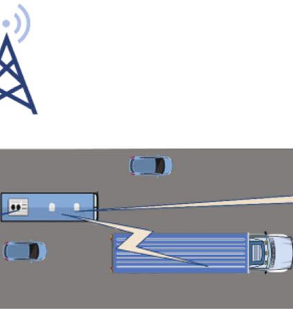
2                                                                            Wireless Communications and Mobile Computing

communication require V2X messages should be delivered              ferred between the RSUs. Therefore, this paper introduces a
reliably and fast [5]. Actually, besides information about          method that data packets can be transferred to the MEC in
safety, every information should be transmitted in time and         the farther road in advance by using V2V and V2I communi-
correctly by using this route.                                      cations to reduce the latency of the computation off load.
     The routes used for communication are established by a              Reference [13] introduces an algorithm based on ant col-
routing protocol, such as AODV (Ad hoc On-demand                    ony optimization (ACO) to avoid congestion accidents when
Vector Routing), DSDV (Destination-Sequenced Distance               communicating. ACO takes inspiration from the foraging
Vector), and DSR (Dynamic Source Routing). The tradi-               behavior of ants. Ants can mark some favorable paths that
tional routing protocols used in VANET can be classified into        could be followed by other members [14]. The iteration
two kinds of protocols. One is proactive routing protocol, the      count value in each RSU in all the subsets will decrease by
other one is reactive routing protocols. However, no one kind       time and increase when a vehicle passes by. The shortest
of these traditional routing protocols is suitable for all          route will be found by comparing all RSUs’ iteration counts
VANET scenarios [6]. Also, because vehicles drive in a high         and the larger the iteration count is, shorter the route is.
speed, the topology in VANET can be very complicated soon           Thus, after finding the shortest path in each subset, they are
[7]. Packets should be delivered in a low latency; otherwise,       connected together between the source and destination to
the information in packet would be useless. Moreover,               make sure the message can be sent efficiently
because some packets may contain important safety informa-               The adaptive quality-of-service (QoS) based routing pro-
tion and some information may be about video and audio,             tocol proposed in [15] can choose the interactions which
the communication route should be stable so that vehicles           packets pass to select the route which can fulfill the best
can receive and decode information in packets successfully.         QoS by using an ACO-based algorithm. The ACO-based
Also, the spectrum resource is more and more precious in            algorithm can explore the available candidate paths by using
the 5th-generation mobile networks. Too many V2X com-               forward ants and choose the optimal route by using back-
munications at the same time and sensor networks in a small         ward ants between two terminal intersections. The local
area on the road can cause the link congestion and consume          QoS models for the local road segment can be used to esti-
too much energy, respectively, which breach the concept of          mate real-time pheromone, which can alleviate network con-
green communication [8]. Like the communication in the              gestions and have an efficient communication.
industrial internet of things (IIOT), it is important to allocate        In order to avoid congestions and increase the efficiency
the power and resources for the integrated network to               when communicating, it is important to aggregate data in
decrease the system cost [9]. As a result, VANET needs an           communications. Vehicles communicating by clusters is
efficient communication mechanism to prevent network                  one of these methods. Reference [16] points out that the clus-
congestion in order to ensure the reliability of communica-         ter heads (CHs) can perform cooperative spectrum sensing to
tion between vehicles and other devices. Also, communica-           get available spectrum, which can efficiently deduce the aver-
tion with data aggregation can save bandwidth resources             age total throughput and balance the whole system energy.
and support a large-scale vehicular network [10].                   Also, reference [17] implements major routing mechanisms
     Therefore, V2X communications in VANET need a sta-             in cluster-based routing protocol (CBRP). In each cluster,
ble, low-latency, and efficient route to exchange information.        there is a cluster head (CH) serving as the relay node which
                                                                    is responsible for forwarding data packets between the source
2. Related Work                                                     and destination. It maintains a less overlapping 1-hop
                                                                    cluster-head-based cluster structure. Each node can send
Reference [11] introduces an edge computing solution to             out “Hello” message including its own information to its 1-
enhance the efficiency of content delivery. In the architecture       hop neighbors. In order to have a greater cluster, the CH’s
proposed, the intelligence at the wireless edge (i.e., base sta-    neighboring CHs could be 2 or 3 hops away and the other
tions and autonomous vehicles) can be made full use of for          nodes in the CH’s route table would be cluster members
coordinated content delivery. An edge server is added at each       (CMs). If the destination node is not in the route table of
BS to serve as an agent between cloud servers and vehicles for      source node, the source node will send a route request
content delivery. Also, the resources at BSs are greater than       (RREQ) to discover the route. The data from the source node
those on vehicles. Not only can those be utilized to cache          and destination node will be transferred through the cluster
contents for all kinds of services usually required but also it     head and cluster gateway (CGW). CGWs are the cooperative
can be used to compute the data from vehicles and servers.          nodes that include their neighboring cluster information and
Therefore, when the density of vehicles grows, this architec-       know their 3-hop neighboring CHs. This kind of structure is
ture can reduce the burden on cellular network and decrease         more stable and efficient than traditional routing protocols
the transmission delay.                                             and can increase the network traffic load or size.
    Moreover, [12] points out that vehicles may pass through             The mobility prediction-based clustering (MPBC)
several RSUs due to the high driving speed and the sending          scheme proposed in [18] is designed for ad hoc networks
back of the computation data output needs to be transmitted         with high-speed nodes which can improve the scalability
through several MEC (mobile edge computing) servers in the          and stability. The node will periodically exchange “Hello”
traditional communication architecture used edge servers.           messages between its neighbors to estimate their relative
However, in order to improve the transmission efficiency of           speeds. In the start of clustering, the node with the smaller
the wireless backhauls, the task-input file cannot be trans-         speed and the greater number of neighbors in the cluster will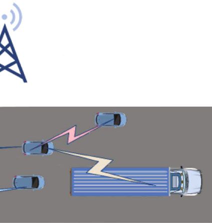
Wireless Communications and Mobile Computing                                                                                    3

be easier to become the CH. During the time when the net-          to the vehicle attribute information such as the vehicle type,
work maintains the cluster, it will use mobility prediction        the number of neighboring vehicles, the total distance, and
strategies to extend the connection lifetime for each node         the speed at the same time. The first level of network is CH,
and make the clusters more stable. When a CM is going to           and the second level is CM. Therefore, it can aggregate the
run out of the limited transmission range, it will choose the      communication data more efficiently and possibly avoid data
cluster that it may stay in for the longest time. When two         congestion. Also, this algorithm takes the condition of each
CHs and their own clusters come into each other’s coverage         node into account.
area, the CH with the smallest relative speed will become              The two-level communication routing algorithm is based
the new cluster head of these two clusters. This scheme has        on the cluster information from the two-level cluster algo-
longer connection time and can increase the network stability      rithm. In order to communicate more efficiently, the algo-
and scalability.                                                   rithm does not have the CGW. The algorithm is based on
     In summary, V2X communications in VANET need to               AODV; thus, it could have a bigger size of cluster and a lower
establish routes before communicating. The proactive rout-         overhead which is different from CBRP and more suitable for
ing protocols such as AODV only find the route to destina-          VANET. After vehicles are clustered, the source vehicle node
tion when the source needs to communicate. Although this           will communicate with the destination vehicle node through
can save the overhead of the network, the transmission delay       this algorithm.
is high. The reactive routing protocols such as DSDV will              The existing researches on VANET routing algorithms
maintain all available routes in each node’s routing table by      are mostly set on the background of nodes that can move
exchanging messages periodically. Although, it is helpful to       randomly in the scene set, which does not conform to the
decrease the communication delay, the overhead of the net-         truth that vehicles can only move in such particular lanes
work is higher. Due to the fact that the VANET has the char-       according to the traffic rules under the limited legal speed.
acteristics of high data capacity, low-latency demand, and         This paper utilizes Simulation of Urban Mobility (SUMO)
high nodes’ speed, it is important to improve the structure        to simulate vehicles’ movements on real road lanes in the real
of the network or the traditional routing protocols in order       world under the traffic rules to truly show the advantages of
to provide VANET with a stable, low-latency, and efficient           the routing algorithm proposed.
route for vehicles to communicate with each other.                     The rest of this paper is listed below. Section 3 describes
     However, although the network added with MEC servers          the two-level cluster algorithm. Section 4 introduces the
may decrease the transmission delay when communicating, it         two-level communication routing algorithm. Section 5 dis-
does not solve the problem of congestions when lots of vehi-       cusses the communication performance results of the routing
cles communicate with each other in a small area on the road.      algorithm proposed and traditional routing algorithm. Sec-
It is necessary to aggregate data or find a better route for the    tion 6 concludes this paper based on the results above.
high number of vehicles in V2X communications to possibly
avoid data congestion. Although the routing algorithms
added with ACO may find a better route from source to des-          3. Two-Level Cluster Algorithm
tination, it has the characteristics of high complexity. Because
                                                                   In this section, we introduce a cluster algorithm which can
the route in ACO needs much time to accumulate, it is not
                                                                   cluster the vehicles on the road and select the CHs based on
suitable to use in the VANET whose topology and surround-
                                                                   vehicle attribute information. The cluster algorithm executed
ing scene change rapidly, which is not beneficial for routes to
                                                                   by vehicles can aggregate communication data with the help
be formed. Finally, although CBRP aggregates the communi-
                                                                   of CHs.
cation data and decreases the possibility of data congestion in
a certain degree in V2X communications by clustering the
vehicles on the road compared with the traditional routing         3.1. The Vehicle Attribute Information. In the exiting cluster
protocols, the CH is selected only according to the mobility       algorithms, CHs are selected by only one kind of nodes’ attri-
and the number of neighboring vehicles in the limited dis-         bute information. Therefore, these algorithms are not suit-
tance. It does not consider all nodes’ characters comprehen-       able to be used in VANET due to the fact that the vehicle
sively when selecting the CH. Also, the size of CBRP’s cluster     nodes in VANET have much more specific information
is 1 hop to 2 hop. It is designed for MANET and is not suit-       which is different from the nodes in ordinary MANETs.
able for VANET for the size of cluster in VANET is much                 The vehicle attribute information we use in this algo-
bigger than 2 hop. If the cluster size were to be as small as 2    rithm is below.
hop, the overhead of the whole network will increase fast as            The first one is the vehicle type Ci of the vehicle node i.
the number of clusters and CHs grows. And the CGW will             The common three kinds of vehicle type on the road are
make the structure more complex.                                   the buses, the trucks, and the cars. C i is an important attri-
     In this paper, we propose a two-level cluster algorithm       bute information that differentiates vehicles nodes in
and a two-level communication routing algorithm. And the           VANET from nodes in MANET. The CH serving as buses
major contributions of this paper are as follows.                  is the most stable because the buses’ trace is the most stable
     Firstly, the two-level cluster algorithm proposed con-        among these three types of vehicles. The CH serving as cars
siders the vehicle nodes’ attribute information comprehen-         can cause the least shadow fading when vehicles communi-
sively. It clusters the vehicles on the road with a limited        cate because the cars’ volume is the smallest, and the trucks’
distance threshold and periodically selects the CHs according      volume is the biggest among these three types of vehicles.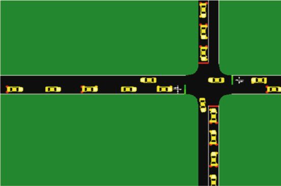
4                                                                                                       Wireless Communications and Mobile Computing

We consider the impact of each kind of vehicle on communi-                                                         Table 1: The value of C i .
cation and set the value of C i in Table 1.
       The second one is the number of neighboring vehicles                                   Type                                                             Value
N i,t . It is the number of neighboring vehicles in the limited                               Bus                                                               1
distance threshold of the vehicle node i at time t. Once the                                  Car                                                               2
distance between the source nodes and the destination nodes                                   Truck                                                             3
surpasses the limited distance threshold, the destination
nodes cannot decode the packets from source nodes cor-
rectly. The limited distance threshold th is 300 m and the size                               distance Di,t , and the speed M i,t of a vehicle node in each
of each cluster is no more than this threshold.                                               cluster at time t. After that, it will select the CHs and the
       The third one is the total distance Di,t . It is the total dis-                        CMs in each cluster at current time t and increase the current
tance between vehicle node i and its each neighboring node                                    time by tim. The details about selecting CHs and CMs will be
j. Use the following formula (1) to obtain the total distance                                 introduced in the next part. Finally, if the current time t + tim
Di ,t .                                                                                       is smaller than the stop time, the algorithm will be executed
                                                                                              again.
                      rffiffiffiffiffiffiffiffiffiffiffiffiffiffiffiffiffiffiffiffiffiffiffiffiffiffiffiffiffiffiffiffiffiffiffiffiffiffiffiffiffiffiffiffiffiffiffiffiffiffi
                    n
                         n
                                                                  2                            The details about this part are shown in Algorithm 1.
         Di , t = 〠 〠    xi,t − x j,t 2 + yi,t − y j,t ,                                ð1Þ
                  i=1 j=1, j≠i                                                                3.3. Select CHs in Each Cluster. This part is about how the
                                                                                              cluster algorithm selects the CHs in each cluster at time t in
      where n is the total number in the whole scene. xi,t is the                             part 3.2. It will firstly calculate the weighted count wi,t of
coordinate on the x axis of the vehicle node i at time t. x j,t is                            the vehicle node i at time t based on the four kinds of attri-
the coordinate on the x axis of the vehicle node j at time t.                                 bute information above. Use the following formula (3) to cal-
yi,t is the coordinate on the y axis of the vehicle node i at time                            culate the wi,t .
t. y j,t is the coordinate on the y axis of the vehicle node j at
time t.                                                                                               wi,t = λ1 × Ci + λ2 × M i,t + λ3 × Di,t − λ4 × N i,t ,     ð3Þ
      The fourth one is the speed M i,t of a vehicle node. It is the
distance movement per unit time of the vehicle node i at time                                 where λi is the weight of each attribute information.
t within the algorithm execution interval tim. Because the tim                                     From Table 1, we can infer that the CH served as the node
is short, the distance movement per unit time can be approx-                                  with the smaller value of C i may cause the less negative effect
imately regarded as the speed. Use the following formula (2)                                  when vehicles communicate. Also, the lower the speed of a
to obtain the speed M i,t of a vehicle.                                                       vehicle node is, the more stable the route established through
                    qffiffiffiffiffiffiffiffiffiffiffiffiffiffiffiffiffiffiffiffiffiffiffiffiffiffiffiffiffiffiffiffiffiffiffiffiffiffiffiffiffiffiffiffiffiffiffiffiffiffiffiffiffiffiffiffiffiffiffiffi
                                                                            2ffi
                                                                                              this node is. Therefore, the CH served as the node with the
                     ðxi,t − xi,t−tim Þ2 + yi,t − yi,t−tim                                    smaller speed may be beneficial for communication. More-
          M i,t =                                                                   ,   ð2Þ   over, the smaller the total distance Di,t is, the closer the node
                                               tim
                                                                                              is to the center of the cluster. Therefore, the route established
    where xi,t−tim is the coordinate on x axis of the vehicle                                 through the CH served as the node with the smaller total dis-
node i at time t − tim. yi,t−tim is the coordinate on the y axis                              tance may have the lower communication latency. Finally,
                                                                                              the more the number of neighboring vehicles N i,t is, the more
of the vehicle node i at time t − tim.
    These four kinds of attribute information in the algo-                                    neighboring nodes can be covered in the cluster. Therefore,
rithm proposed are important due to the fact that not only                                    the CH served as the node with the greater number of neigh-
they represent the properties of the vehicles but also they                                   boring vehicles can aggregate more data packets when com-
measure the connectivity between different vehicles. It is ben-                                municating and the route established through this node can
eficial for vehicles to communicate through clusters.                                          be more efficient. In conclusion, the cluster algorithm will
                                                                                              select the node with the smallest weighted count wi,t to be
3.2. Cluster the Vehicles on the Road. In this part, the cluster                              the CH in each cluster at time t.
algorithm will firstly judge the current time t is whether                                          When selecting the CHs at time t, the algorithm will
smaller the stop time. If the current time t is 0, it will increase                           firstly check whether the sequence number of the node is
the current time by tim after regarding the current coordi-                                   greater than the total number of the nodes. If so, the algo-
nate as the initial coordinate. The algorithm is executed from                                rithm will stop and the latest cluster information will be used
node zero. During the execution of the cluster algorithm in                                   in the two-level communication routing algorithm next.
each interval, it will firstly calculate the distance between a                                     If the sequence number of the node is smaller than the
node and the other nodes in the scene. And the nodes will                                     total number of the nodes, the cluster algorithm will check
be clustered into a same cluster when the distance between                                    whether the node has been classified as a CM or CH in any
nodes is less than the th. If a node has no neighbors within                                  cluster at time t. If the node has been a CM or CH at time t
the th, there will be only one node in this cluster. The algo-                                , the cluster algorithm will check the next node. Otherwise,
rithm will keep clustering the nodes until all the nodes are                                  the algorithm will check if the node has neighboring nodes
clustered. After clustering the nodes, the algorithm will cal-                                or not at time t. If it has no neighboring nodes, it will be
culate the number of neighboring vehicle nodes N i,t , the total                              selected to be the CH of itself at time t. If it has neighboring
Wireless Communications and Mobile Computing                                                                                          5

                               Operation Flow
                               1:    Input: the current time, the stop time, and the attribute information
                               2:    While the current time is smaller than the stop time
                               3:         if the current time is 0
                               4:            regard the current coordinate as the initial coordinate
                               5:            increase the current time by tim
                               6:         get the current coordinate of each node
                               7:         calculate the distance between a node and other nodes in the scene
                               8:         cluster the vehicles on the road
                               9:         calculate the number of neighboring vehicle nodes
                               10:        calculate the total distance among each node
                               11:        calculate the speed of a vehicle node in each cluster
                               12:        select the CHs in each cluster at time t
                               13:        increase the current time by tim
                               14:   End

                                             Algorithm 1: How to cluster the vehicles on the road.

             Operation Flow
             1: Input: the weighted count wi,t
             2: While the sequence number of the node is smaller than the total number
             3:    if the node has not been a CM or CH in any cluster at time t
             4:       if the node has neighboring nodes which are connected to itself and are not in any cluster either at time t
             5:          compare the weighted count among these nodes in the cluster
             6:          select the CH and the CMs in this cluster at time t
             7:       else
             8:          select itself to be the CH
             9:    else
             10:        continue
             11: End

                                  Algorithm 2: How the cluster algorithm selects the CHs in each cluster.

                                        CH                                                       CH

        CH

       Cluster1                              Cluster2                                                 Cluster3

                                                 Figure 1: The model of the cluster algorithm.

nodes connected to itself and not in any cluster either, the algo-           The model in this section about cluster algorithm is
rithm will compare the weighted count wi,t among these nodes             shown in Figure 1.
in the cluster and select the node with the smallest weighted                In Figure 1, there are three kinds of vehicles, i.e., cars,
count to be the CH in this cluster and the other nodes will              buses, and trucks. Also, there are three clusters on the road
become the CMs in this cluster at time t. After that, the algo-          at current time t. The cluster head is labelled by “CH” in each
rithm will check the next node and will be executed again.               cluster while others are cluster members in each cluster.
     After checking all nodes and selecting CHs in all clusters
at time t, the algorithm will increase the current time by tim.          4. Two-Level Communication
If the current time t + tim is still smaller than the stop time,            Routing Algorithm
the algorithm in part 3.2 will be executed again.
     The details in this part which is about selecting the CHs           In this section, we introduce a two-level communication
in each cluster at time t is shown in Algorithm 2.                       routing algorithm based on the cluster information above.
6                                                                                Wireless Communications and Mobile Computing

                              Operation Flow
                              1: Input: cluster information
                              2: If the node index is the source of the RREQ it received
                              3:    discard this RREQ
                              4: else
                              5:    set up a reverse route or update the exiting reverse route
                              6:    read the cluster information from the cluster algorithm
                              7: End

                           Algorithm 3: The initial part of the two-level communication routing algorithm.

           Operation Flow
           1:    Input: cluster information
           2:    If the ih − >saddrðÞ is the source of the RREQ it received
           3:         if the ih − >saddrðÞ and the node index are in the same cluster
           4:              node index sends RREP
           5:              free this RREQ
           6:         else
           7:              free this RREQ
           8:    else
           9:         if the destination node index is the CH½index and the ih − >saddrðÞ is the CH dst prehop½ih−>saddrðÞ
           10:             node index sends RREP
           11:             free this RREQ
           12:        else
           13:             if ih − >saddrðÞ is the CH½index
           14:                   node index sends RREP
           15:                   free this RREQ
           16:   End

                                          Algorithm 4: How destination nodes send RREP.

The source node will communicate with the destination node
with the help of the reliable CHs in the clusters.                                  Situation 1.1
                                                                                                             S             D
     The society is stepping into the era of big data, and the
spectrum resources are facing serious shortage. Therefore, it                                                     R
                                                                                    Situation 1.2.1      S                     D
is important to guarantee the spectrum access probability of
each user in the network [19]. And the algorithm we propose
in this section is beneficial for aggregating the data when                          Situation 1.2.2      S        R            D
communicating and saving the precious spectrum resource.
Therefore, it can provide the communication with a stable                                 CH
and efficient route.
     In the exiting routing algorithms such as AODV, DSR,                                 CM
and DSDV, all nodes are in one level; it can cause data packet                      S: the source node
congestion and even loss when the number of communicat-                             D: the destination node
ing vehicles increases. Also, these routing algorithms can also                     R: the relay node
waste the communication resource because of the lack of data                              : the hop count is 1
                                                                                          : the hop count is more than 1
aggregation. Therefore, these routing algorithms need to
effectively aggregate the data when communicating.                     Figure 2: All kinds of situations about the destination node replying
     In the exiting cluster routing algorithms such as CBRP,          a RREP.
the size of clusters is small and it is suitable for MANETs with
small scene. It is not suitable for VANETs because the scene
in VANETs may be much greater and much more complex.                  the cluster information obtained from the section above to
Also, the CGWs in CBRP may cause the waste of communi-                fit in with the needs of the VANETs and the data aggregation.
cation resource when communicating. Therefore, these clus-
ter routing algorithms need to be improved in order to adapt          4.1. Route Discovery and Maintenance in AODV. AODV is
to the scene in VANETs.                                               an on-demand route algorithm. The nodes do not need to
     Therefore, we propose a two-level communication rout-            maintain the route to destination all the time. The node will
ing algorithm based on an existing routing algorithm and              discover and maintain the route only when the source node
Wireless Communications and Mobile Computing                                                                                          7

                           Operation Flow
                           1:    Input: cluster information
                           2:    If the intermediate node index has the valid route to the destination
                           3:       node index sends RREP and GRAT_RREP
                           4:       free this RREQ
                           5:    else
                           6:       if the intermediate node index is the CH
                           7:              if the ih − >saddrðÞ is the source node
                           8:                 if the source node is the CH
                           9:                     broadcast this RREQ
                           10:                    free this RREQ
                           11:                else
                           12:                      if the source node and the node index are in the same cluster
                           13:                            broadcast this RREQ
                           14:                            free this RREQ
                           15:                       else
                           16:                            free this RREQ
                           17:             else
                           18:                  if the ih − >saddrðÞ is the CH of itself
                           19:                      broadcast this RREQ
                           20:                      free this RREQ
                           21:                  else.
                           22:                      free this RREQ
                           23:      else
                           24:           free this RREQ
                           25: End

                                       Algorithm 5: How intermediate nodes broadcast RREQ.

communicates with the destination node. Although AODV                                  Situation 3.1.1   S           R        D
uses a broadcast route discovery mechanism like DSR,
AODV establishes the route table entries at intermediate
nodes dynamically, which can effectively decrease the over-                             Situation 3.1.2   S        R           D
head in packets. Also, AODV utilizes the sequence numbers
of packets like DSDV; however, each node in AODV main-
tains a monotonically increasing sequence number counter                               Situation 3.2     S       R       R        D
[20]. Therefore, the two-level communication routing algo-
rithm proposed is based on AODV.                                                            CH
    In AODV, the source node will only broadcast RREQ                                       CM
(route request) targeting the destination node when a source                           S: the source node
node needs a route to destination node. An intermediate                                D: the destination node
node will firstly set up a reverse path to the source node                              R: the relay node
and regard the previous hop of the RREQ as the next hop                                      : the hop count is 1
of this reverse path. If the intermediate node has a valid route                             : the hop count is more than 1
to the destination node or the node is the destination node, it
                                                                        Figure 3: All kinds of situations about the intermediate node
will send a RREP (route reply) to the source node via the
                                                                        broadcasting the RREQ.
reverse path. Otherwise, the intermediate node will rebroad-
cast the RREQ and the other nodes will discard the duplicate
copies of the RREQ. A forward path will be successfully
established to transfer data packets after the source node
receives the RREP from the destination node [21].                       routing algorithm based on AODV and the cluster
    When a route is broken, the nodes in this route will be             information.
notified with RRER (route error) packets which are intended                  In this algorithm, when the node index receives a RREQ,
to inform all sources using this failed route and the source            it will firstly drop this RREQ if it is the source of this RREQ.
nodes will discovery a new route if it is needed [22].                  Otherwise, the node index will set up a valid reverse path rt0
                                                                        or update the exiting rt0 to the source node. The previous
                                                                        hop of the RREQ is the next hop of this reverse path. In
4.2. The Two-Level Communication Routing Algorithm. In                  AODV, the node index is the node that is currently executing
this part, we will introduce the two-level communication                the algorithm.
8 Wireless Communications and Mobile Computing
CH CH
CH
Cluster1 Cluster2 Cluster3
Figure 4: The model of the two-level communication routing algorithm.
After the establishment or the update of the rt0, the algo-
rithm will read the cluster information from the cluster algo-
rithm in the above section. The algorithm will regard the ith
CH as cluster½i½0 and regard the jth CM in the ith cluster as
cluster½i½j. Also, it will regard the CH of index as CH½index. (a) The one-lane road (b) The two-lane road
The initial part of the two-level communication routing
algorithm is shown in Algorithm 3.
After that, the node index will check whether itself is the
destination of the RREQ. And it will regard the prehop of this
RREQ as ih − >saddrðÞ.
Situation 1. If the index is the destination of the RREQ, the
algorithm will denote the CH of the pre-hop of this RREQ
as CH dst prehop½ih−>saddrðÞ. (c) The two-lane road intersection
Figure 5: Three kinds of real street scenes.
Situation 1.1. If now the ih − >saddrðÞ is the source of this
RREQ, which means that the hop count of the RREQ is only
one. Therefore, in order to communicate effectively, the des- Table 2: The parameters of the communication.
tination node index will send a RREP to the source node
directly if they are in the same cluster. If they are not in the Parameter Value
same cluster, the algorithm will free this RREQ. The number of vehicles 10, 20, 30, 40, 50, 60, 70
The type of vehicles 3
Situation 1.2. If now the ih − >saddrðÞ is not the source of The maximum of the limited
this RREQ, it means that this RREQ is broadcasted by inter- 5, 7.5, 10, 12.5, 15, 17.5, 20
speed on lanes (m/s)
mediate nodes. The destination node index will only send a The size of the scene 1100 m × 1100 m
RREP in the following situations.
The stop time (s) 300.0
MAC protocol 802.11
Situation 1.2.1. The destination node index is the CH½index
AODV, the algorithm
and at the same time the ih − >saddrðÞ is CH dst prehop½ih Routing algorithm
we propose
−>saddrðÞ.It means that the node index is the CH of index
and the ih − >saddrðÞ is the CH of ih − >saddrðÞ. It ensures Transport layer protocol TCP
that only the CH can successfully receive and forward the The rate of communication nodes 0.5
RREQ. Algorithm execution interval tim (s) 1
The limited distance threshold th (m) 150
Situation 1.2.2. ih − >saddrðÞ is the CH½index. It means that
the ih − >saddrðÞ is the CH of index. It ensures that the des-
tination node will only receive the RREQ from its CH when Situation 2. If the index is not the destination of the RREQ
the destination node is not a CH. but the intermediate node has a valid route to the destination,
the node index will send a RREP to the source node and also
The operation flow about how the destination nodes send send a GRAT_RREP to the destination node.
the RREP to establish the route is shown in Algorithm 4.
All kinds of situations about the destination node reply- Situation 3. If the intermediate node index does not have a
ing a RREP are shown in Figure 2. The nodes in the same valid route to the destination, the algorithm will denote the
cluster have the same color. source node of this RREQ as CH src½rq−>rq src and it willWireless Communications and Mobile Computing 9
0.045
0.04
0.035
The rate of packet loss
0.03
0.025
0.02
0.015
0.01
0.005
0
10 20 30 40 50 60 70
The number of vehicles
The routing algorithm proposed
Traditional AODV
(a) The rate of packet loss
0.75
0.7
The average transmission delay (s)
0.65
0.6
0.55
0.5
0.45
0.4
0.35
0.3
10 20 30 40 50 60 70
The number of vehicles
The routing algorithm proposed
Traditional AODV
(b) The average transmission delay
Figure 6: Continued.10 Wireless Communications and Mobile Computing
0.6
The proportion of normalized routing overhead
0.5
0.4
0.3
0.2
0.1
0
10 20 30 40 50 60 70
The number of vehicles
The routing algorithm proposed
Traditional AODV
(c) The proportion of normalized routing overhead
Figure 6: The communication performance of the two routing algorithms on the condition that the maximum of the limited speed is 15 m/s.
also regard the CH of ih − >saddrðÞ as CH relay prehop½ih The source node will communicate with the destination
−>saddrðÞ. In Situation 3, only the intermediate node which node through the CH on the route. The model of this algo-
is the CH can broadcast the RREQ successfully. rithm is shown in Figure 4. The communication with the
same color is the same.
Situation 3.1. If the ih − >saddrðÞ is the source node, it means
that the intermediate node index is the first intermediate node.
The intermediate node index will only broadcast this RREQ in 5. Simulation Results
the following situations. It ensures that the first intermediate
node can only broadcast the RREQ from the source node In this section, vehicles will communicate with each other
which is the CH or the CM of the first intermediate node. through the two-level communication routing algorithm
and the traditional AODV routing algorithm by the help of
Situation 3.1.1. The source node is the CH of itself. NS2 (Network Simulator version 2). And we choose some
real street scenes to simulate the movement of vehicles in real
world by using SUMO (Simulation of Urban Mobility).
Situation 3.1.2. The source node and the intermediate nodes
SUMO is an open-source traffic simulator. We compare the
are in the same cluster.
communication performance of the two-level communica-
tion routing algorithm proposed with that of the traditional
Situation 3.2. If the ih − >saddrðÞ is not the source node, it routing algorithm in order to verify the reasonability and
means that this RREQ reaches the intermediate node index superiority of the algorithm proposed.
through other intermediate nodes. The intermediate node We choose three kinds of real street scenes, namely, the
index will only broadcast the RREQ it received when the ih one-lane road, the two-lane road, and the two-lane intersec-
− >saddrðÞ is the CH, namely, the CH relay prehop½ih−> tion. The specific situation is shown in Figure 5.
saddrðÞ. It ensures that only the intermediate node as the The parameters of the communication are shown in
CH can broadcast the RREQ to find the route to the destina- Table 2.
tion from the second intermediate node. Use the following formulas (4), (5), and (6) to calculate
The operation flow about how the intermediate nodes the rate of packet loss L, the average transmission delay T,
broadcast the RREQ they revive is shown in Algorithm 5. and the proportion of normalized routing overhead O,
All kinds of situations about the intermediate node respectively.
broadcasting the RREQ are shown in Figure 3. The nodes
in the same cluster have the same color.
The two-level communication routing algorithm we pro-
pose considers all kinds of situations of the source nodes, the The total number of packets received
L= , ð4Þ
destination nodes, and the intermediate nodes. The total number of packets sentWireless Communications and Mobile Computing 11
0.03
0.025
The rate of packet loss
0.02
0.015
0.01
0.005
5 7.5 10 12.5 15 17.5 20
The maximum of the limited speed (m/s)
The routing algorithm proposed
Traditional AODV
(a) The rate of packet loss
0.8
The average transmission delay (s)
0.7
0.6
0.5
0.4
0.3
5 7.5 10 12.5 15 17.5 20
The maximum of the limited speed (m/s)
The routing algorithm proposed
Traditional AODV
(b) The average transmission delay
Figure 7: Continued.12 Wireless Communications and Mobile Computing
0.6
The proportion of normalized routing overhead
0.5
0.4
0.3
0.2
0.1
0.0
5 7.5 10 12.5 15 17.5 20
The maximum of the limited speed (m/s)
The routing algorithm proposed
Traditional AODV
(c) The proportion of normalized routing overhead
Figure 7: The communication performance of the two routing algorithms on the condition that the maximum of the number of vehicles is 60.
The duration between the first and the last packet On the condition that the number of vehicles is the same,
T= , ð5Þ the rate of packet loss of the algorithm we propose is smaller
The total number of packets sent
than the traditional AODV. The average value is reduced
The number of routing packets about 1%.
O= : ð6Þ Therefore, the route established by the two-level commu-
The total number of packets sent
nication algorithm we propose is much more stable than the
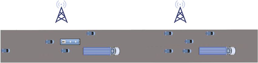
Figure 6 shows the communication performance of the traditional routing algorithm.
two routing algorithms on the condition that the maximum
of the limited speed is 15 m/s. 5.2. The Average Transmission Delay. On the condition that
Figure 7 shows the communication performance of the the maximum of the limited speed on the lane is same, the
two routing algorithms on the condition that the number of average transmission delay is smaller than the traditional
vehicles is 60. AODV.
In the real-world scenes, the distance among the vehicles On the condition that the number of vehicles is same, the
is close like the distance in the real world. Also, the vehicles average transmission delay is smaller than the traditional
move according to traffic rules in the real world. Moreover, AODV.
there will always be the same traffic jam or smoothness which The average value is both reduced about 100 ms in both
is similar to the real world, as well as there will often be a conditions.
large number of vehicles that are close communicating at Therefore, the route established by the two-level commu-
the same time. Therefore, the real-world scenes we set are nication algorithm we propose has a lower latency than the
more suitable to simulate the communication in VANET traditional routing algorithm.
than the random moving scenes used in other researches.
Although, the data fluctuates slightly, it is conceivable 5.3. The Proportion of Normalized Routing Overhead. Com-
because the curves have the same trend since the two algo- pared to traditional AODV, the proportion of normalized
rithms use the same files when simulating. routing overhead of the two-level communication routing
From the curves above, the following conclusions can be algorithm is much more stable and smaller on the both con-
drawn. ditions. The average value is both reduced about 0.3 in the
both conditions.
5.1. The Rate of Packet Loss. On the condition that the max- Therefore, the route established by the two-level commu-
imum of the limited speed on the lane is same, the rate of nication algorithm we propose is much more efficient than
packet loss of the algorithm we propose is much more stable the traditional routing algorithm.
as the number of vehicles increases. And the rate is also Above all, the two-level communication algorithm is bet-
smaller than the traditional AODV. The average value is ter than the traditional routing algorithm in real street scenes.
reduced about 1.5%. This algorithm establishes a route which has a low rate ofWireless Communications and Mobile Computing 13
packet loss and average transmission delay to communicate [2] L. Hobert, A. Festag, I. Llatser, L. Altomare, F. Visintainer, and
with low routing overhead and meets the need of a stable A. Kovacs, “Enhancements of V2X communication in support
low-latency and efficient route for communication in of cooperative autonomous driving,” IEEE Communications
VANET. Magazine, vol. 53, no. 12, pp. 64–70, 2015.
[3] N. Cheng, F. Lyu, J. Chen et al., “Big data driven vehicular net-
6. Conclusion works,” IEEE Network, vol. 32, no. 6, pp. 160–167, 2018.
[4] S. Chen, J. Hu, Y. Shi et al., “Vehicle-to-everything (v2x) ser-
In this paper, we cluster the vehicles on the roads by compre- vices supported by LTE-based systems and 5G,” IEEE Commu-
hensively considering their most attribute information. We nications Standards Magazine, vol. 1, no. 2, pp. 70–76, 2017.
also carefully select the CH in each cluster every time. [5] X. Ma, J. Zhang, X. Yin, and K. S. Trivedi, “Design and analysis
The vehicles can communicate with each other by using of a robust broadcast scheme for VANET safety-related ser-
the two-level communication routing algorithm proposed vices,” IEEE Transactions on Vehicular Technology, vol. 61,
in VANET. We consider all kinds of nodes in the VANET. no. 1, pp. 46–61, 2012.
Therefore, the source nodes will successfully communicate [6] A. Gupta, R. Singh, D. Ather, and R. S. Shukla, “Comparison of
with the destination nodes through the CHs. The algorithm various routing algorithms for VANETS,” in 2016 Interna-
proposed is based on the routing algorithm AODV and the tional Conference System Modeling & Advancement in
Research Trends (SMART), pp. 153–157, Moradabad, 2016.
cluster information. Not only can it aggregate the communi-
cation data and save more precious communication [7] E. Schoch, F. Kargl, M. Weber, and T. Leinmuller, “Communi-
cation patterns in VANETs,” IEEE Communications Maga-
resources than traditional one-level algorithms but also it
zine, vol. 46, no. 11, pp. 119–125, 2008.
can be more suitable for the VANETs, which have a much
[8] W. Lu, X. Xu, G. Huang et al., “Energy efficiency optimization
bigger size than the MANETs, compared with the existing
in SWIPT enabled WSNs for smart agriculture,” IEEE Trans-
cluster routing algorithms.
actions on Industrial Informatics, 2020.
Also, because the vehicles move by the traffic rules in the
[9] X. Liu, X. Zhai, W. Lu, and C. Wu, “QoS-guarantee resource
real world, the real street scenes we set in the simulation is
allocation for multibeam satellite industrial internet of things
more suitable than the random moving scenes in other with NOMA,” IEEE Transactions on Industrial Informatics,
researches on VANET communication. From the simulation vol. 17, no. 3, pp. 2052–2061, 2019.
results, we can get the conclusion that the rate of packet loss, [10] S. Dietzel, F. Kargl, G. Heijenk, and F. Schaub, “Modeling in-
the average transmission delay, and the proportion of nor- network aggregation in VANETs,” IEEE Communications
malized routing overhead are all superior to the traditional Magazine, vol. 49, no. 11, pp. 142–148, 2011.
routing algorithm. The route established by the algorithm [11] Q. Yuan, H. Zhou, J. Li, Z. Liu, F. Yang, and X. S. Shen,
we propose is much more stable and much more efficient “Toward efficient content delivery for automated driving ser-
than the traditional routing algorithm. And it also has a lower vices: an edge computing solution,” IEEE Network, vol. 32,
latency. Therefore, the algorithm we propose meets the need no. 1, pp. 80–86, 2018.
of a stable low-latency and efficient route for communication [12] K. Zhang, Y. Mao, S. Leng, Y. He, and Y. ZHANG, “Mobile-
in VANET. edge computing for vehicular networks: a promising network
paradigm with predictive off-loading,” IEEE Vehicular Tech-
Data Availability nology Magazine, vol. 12, no. 2, pp. 36–44, 2017.
[13] J. Amudhavel, K. P. Kumar, C. Jayachandrameena,
The data used to support the findings of this study are avail- S. Jaiganesh, S. S. Kumar, and T. Vengattaraman, “An robust
able from the corresponding author upon request. recursive ant colony optimization strategy in VANET for acci-
dent avoidance (RACO-VANET),” in 2015 International Con-
Conflicts of Interest ference on Circuits, Power and Computing Technologies
[ICCPCT-2015], pp. 1–6, Nagercoil, 2015.
The authors declare that they have no conflicts of interest. [14] M. Dorigo, M. Birattari, and T. Stutzle, “Ant colony optimiza-
tion,” IEEE Computational Intelligence Magazine, vol. 1, no. 4,
Acknowledgments pp. 28–39, 2006.
[15] G. Li, L. Boukhatem, and J. Wu, “Adaptive quality-of-service-
This work was supported by the National Natural Science based routing for vehicular ad hoc networks with ant colony
Foundation of China (41861134010), the National Key optimization,” IEEE Transactions on Vehicular Technology,
R&D Program of China (2018YFC0807101), and the Fund vol. 66, no. 4, pp. 3249–3264, 2017.
Project of the Key Laboratory of Communication Network [16] X. Liu and X. Zhang, “NOMA-based resource allocation for
Information Transmission and Distribution Technology cluster-based cognitive industrial internet of things,” IEEE
(HHX20641X002). Transactions on Industrial Informatics, vol. 16, no. 8,
pp. 5379–5388, 2020.
References [17] J. Y. Yu, P. H. J. Chong, and M. Zhang, “Performance of effi-
cient CBRP in mobile ad hoc networks (MANETS),” in 2008
[1] I. Yaqoob, L. U. Khan, S. M. A. Kazmi, M. Imran, N. Guizani, IEEE 68th vehicular technology conference, pp. 1–7, Calgary,
and C. S. Hong, “Autonomous driving cars in smart cities: BC, 2008.
recent advances, requirements, and challenges,” IEEE Net- [18] M. Ni, Z. Zhong, and D. Zhao, “MPBC: a mobility prediction-
work, vol. 34, no. 1, pp. 174–181, 2020. based clustering scheme for ad hoc networks,” IEEE14 Wireless Communications and Mobile Computing
Transactions on Vehicular Technology, vol. 60, no. 9, pp. 4549–
4559, 2011.
[19] X. Liu, C. Sun, M. Zhou, C. Wu, B. Peng, and P. Li, “Reinforce-
ment learning-based multislot double-threshold spectrum
sensing with Bayesian fusion for industrial big spectrum data,”
IEEE Transactions on Industrial Informatics, 2020.
[20] C. E. Perkins and E. M. Royer, “Ad-hoc on-demand distance
vector routing,” Proceedings WMCSA'99, Second IEEE Work-
shop on Mobile Computing Systems and Applications, ,
pp. 90–100, IEEE, New Orleans, LA, USA, 1999.
[21] M. K. Marina and S. R. Das, “On-demand multipath distance
vector routing in ad hoc networks,” in Proceedings Ninth Inter-
national Conference on Network Protocols. ICNP 2001, pp. 14–
23, Riverside, CA, USA, 2001.
[22] C. E. Perkins, E. M. Royer, S. R. Das, and M. K. Marina, “Per-
formance comparison of two on-demand routing protocols for
ad hoc networks,” IEEE Personal Communications, vol. 8,
no. 1, pp. 16–28, 2001.You can also read