A590DSP I A540DSP 4-CHANNEL SMART DIGITAL AMPLIFIERS - INSTALLATION & OPERATION MANUAL EINBAU & BEDIENUNGSANLEITUNG
←
→
Page content transcription
If your browser does not render page correctly, please read the page content below
A590DSP I A540DSP
4-CHANNEL SMART DIGITAL AMPLIFIERS
INSTALLATION & OPERATION MANUAL
EINBAU & BEDIENUNGSANLEITUNG

Thank you for purchasing this innovative AXTON amplifier!                                         SAFETY INSTRUCTIONS
                                                                                                   Do not turn on any function which may distract you while driving the vehicle.
                                                                                                 n
To maximize the performance of this amplifier and your complete car audio system
                                                                                                     Functions requiring sustained attention must only be used when the vehicle is at a
install, we recommend that you acquaint yourself thoroughly with all technical features
                                                                                                     complete standstill. Make sure to always stop your vehicle in a safe place before
and controlling options of this AXTON amplifier. Please read this manual carefully, before
                                                                                                     operating these functions. There is a risk of causing an accident.
attempting the installation. If, after reading this manual, you still have questions regarding
functions or the installation of the amplifier, we recommend that you consult your dealer.         Keep the volume at a low level to be able to hear exterior noises while driving
                                                                                                 n
                                                                                                     the vehicle. There is a risk of causing an accident.
                                                                                                   Do not open the amplifier or undertake any modification of the product. There
                                                                                                 n
                                                                                                     is a risk of accident, fire or electric shock.
                                                                                                   Only use this amplifier with 12V mobile applications. Any other use other than
                                                                                                 n
                                                                                                     the use for which this product has been designed may lead to fire, electric shock or
                                                                                                     injury.
                                                                                                   Use fuses of the correct amperage. There is a risk of fire or electrocution.
                                                                                                 n
                                                                                                   Do not obstruct radiators and/or vents. Internal overheating may occur and cause
                                                                                                 n
                                                                                                     a fire.
                                                                                                   Ensure all connections are properly made. Check the section of cable and the
                                                                                                 n
                                                                                                     type of cable if it does not correspond with the use. There is a risk of fire, injury and/
                                                                                                     or damage to the product.
                                                                                                   Do not use nuts or fasteners part of the steering or braking systems for ground
                                                                                                 n
                                                                                                     connection. The fasteners and nuts used for the brake and steering systems (or any
                                                                                                     other security system) as well as various tanks must never be used for grounding.
                                                                                                     Use of these parts as ground may deactivate the vehicle’s control system and cause
                                                                                                     a fire or other technical problem.
                                                                                                   Keep all small objects which could be swallowed, such as the fasteners and
                                                                                                 n
                                                                                                     screws, out of the reach of children. Swallowing such objects may cause serious
                                                                                                     injuries. In the event of swallowing any of these objects, immediately seek medical
                                                                                                     advice.
                                                                                                   Before starting the installation, disconnect the negative terminal of the battery
                                                                                                 n
                                                                                                     to avoid any risk of injury, fire or damage to the equipment.

                                            –2–                                                                                                –3–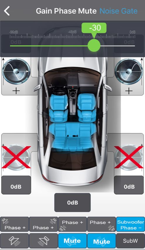
TECHNICAL SPECIFICATIONS A590DSP / A540DSP                                                    INSTALLATION DIAGRAM

                                  A590DSP                     A540DSP
 Music Power Output:*             150 W x 4 @ 4/2 ohms        54 W x 4 @ 4 ohms
 RMS Power Output:*               76 W x 4 @ 4/2 ohms         32 W x 4 @ 4 ohms
 Music Power Output:              100 W x 4 @ 4/2 ohms        n.a.
 RMS Power Output:                50 W x 4 @ 4/2 ohms         n.a.
 Frequency response:              20Hz ~ 20 kHz               20Hz ~ 20 kHz
                                                                                                                                                      ORIGINAL CAR SOCKETS
 Audio sampling frequency:        192 kHz                     192 kHz
 Distortion:                      1 KHz  120 dB
 Dynamic range:                   > 96 dB                     > 96 dB
 Standby current:                 0 mA                        0 mA
                                                                                                                                                        HEAD UNIT
 Maximum operating current:       20 A                        15 A
 Dimensions (LxWxH):              185(218**) x 114 x 40 mm    145(177**) x 114 x 40 mm

* With additional power supply.
** Including BT antenna.

 MAIN FEATURES
n   4-channel Smart Digital Amplifier with iOS or Android App controlled audio DSP
    functions
n   DSP-controlled 5-channel Preout (6 Volt) including REM out to control additional
    amplifiers
n   Bluetooth Audio Streaming with automatic source switching                                  MOUNTING INSTRUCTIONS
n   Plug’N’Play quick installation system via optional vehicle brand and model specific ISO
    wire harness
                                                                                              1. Before you start with the installation, make sure you know the security code of your
n   Auto-Turn-On function
                                                                                                 headunit (if applicable).
                                                                                              2. Remove the headunit from the dashboard and disconnect the main wire.
 FUNCTIONALITY & ADJUSTABILITY
                                                                                              3. Find a place for the A590DSP or A540DSP and connect the provided (or optionally
n   Bluetooth connection and control of DSP settings via iOS or Android Smartphone App           available car-specific) wire to the amp.
n   Freely configurable active crossover: High-/Low-/Band-/Bypass with 6/12/18/24dB/
     Oct. slope for Front, Rear and Subwoofer channel                                         4. A590DSP only: For more power output please follow these steps: Run a 10 mm2
n   Time Alignment in cm (0 – 420 cm) for front, rear and subwoofer channel                      power wire from the (+) pole of the battery to the (BATT) terminal of the amplifier.
n   5 channel control: Gain, Phase switch and Mute function for each speaker                     Use a fuse with the related value of the cross section of the power wire. The distance
n   Freely configurable 10 or 31-band parametric Equalizer for every single front and rear       between the B+ pole and the fuse holder must be 30 cm or less. Run the minus cable
     speaker                                                                                     with the same cross section from the (GND) terminal of the amp to the vehicle chassis
n   Freely configurable 5-band parametric Equalizer for subwoofer channel                        ground. Make sure that the contact surface is clean in order to get best conductance.
n   Can save 5 memories in the amp and unlimited sound settings on the smartphone             5. Connect the wire to the headunit.
n   Dynamic Bass setting for powerful performance without subwoofer
n   Noise Gate function to reduce car stereo background noise                                 6. Install the headunit back in the dashboard.

                                             –4–                                                                                        –5–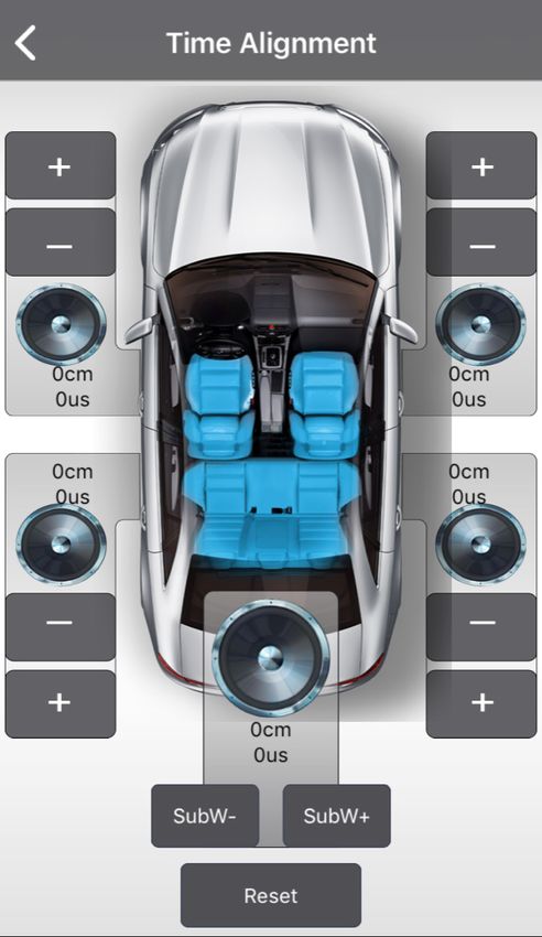
WIRING DIAGRAM A590 DSP WIRING DIAGRAM A540 DSP
Installation Diagram
If you want to use just the DSP function of the A590DSP with a separate high performance If you want to use just the DSP function of the A540DSP with a separate high performance
amplifier, connect the line out of the A590DSP with the RCA input of your amplifier. amplifier, connect the line out ofUSER
theMANUAL
A540DSP with the RCA input of your amplifier.
SPEAKER SPEAKER
Wire Diagram
20 20
20
FR+in RR-out
FR-in RR+out
FL+in RL-out
FL-in RL+out
1* ACC-in 11 GND 1* ACC-in 11 GND
RL+in FR-out
RL-in FR+out
RR+in FL-out
Installation Diagram
RR-in FL+out
GROUND (-) BATTERY (+) FUSE 2* Rem-out 12 +B +B
GND
Model No.: MDA-100
2* Rem-out 12 +B
ANTENNA USER MANUAL SPEAKER REMOTE POWER ANTENNA
3 RR-in 13 FL+out 3 RR-in 13 FL+out
SPEAKER IMPEDANCE
4 RR+in 14 FL-out 4 RR+in 14 FL-out
5 RL-in 15 FR+out 5 RL-in 15 FR+out
6 RL+in 16 FR-out 6 RL+in 16 FR-out
Wire Diagram
7 FL-in 17 RL+out 7 FL-in 17 RL+out
20
FR+in RR-out
FR-in RR+out
FL+in RL-out
FL-in
RL+in
RL+out
FR-out
8 FL+in 18 RL-out 8 FL+in 18 RL-out
RL-in FR+out
9 FR-in 19 RR+out 9 FR-in 19 RR+out
RR+in FL-out
RR-in FL+out
+B
GND
Model No.: MDA-100
FRONT/REAR FRONT/REAR
FRONT/REAR SPEAKER REMOTE POWER 10 FR+in 20 RR-out LINEOUT LINE IN 10 FR+in 20 RR-out
LINEOUT
1* In some cases with old headunits the Auto-Turn-On function cannot work. If you meet this problem, please 1* In some cases with old headunits the Auto-Turn-On function cannot work. If you meet this problem, please
just put the separately provided wire “ACC-IN” into the connector of the connection cable and connect it to just put the separately provided wire “ACC-IN” into the connector of the connection cable and connect it to
ACC/Amp Remote of the car stereo or another cable which will provide +12 V only when the car stereo is ACC/Amp Remote of the car stereo or another cable which will provide +12 V only when the car stereo is
turned on. Secondly select “REMOTE TURN ON” on the remote switch. turned on. Secondly select “REMOTE TURN ON” on the remote switch.
2* REM-Out: Connect this wire to the remote input of a separate amplifier, for example a mono amp for a 2* REM-Out: Connect this wire to the remote input of a separate amplifier, for example a mono amp for a
subwoofer. subwoofer.
DIMENSIONS A590 DSP DIMENSIONS A540 DSP
Model No.: MDA-100
185 mm 145 mm
USER MANUAL
POWER PROTECT
(20 A)
FUSE
4Ω
REMOTE TURN ON
SIGNAL TURN ON
2Ω
A590DSP
SUB R
SUB L
BATT.
SPEAKER LEVEL
INPUT/OUTPUT
POWER IN
LINE OUT
114 mm
114 mm
RR
RL
GND
Installation Diagram
Wire
FL
FR
Diagram
FR
FL
RR+out
FR+out
RL+out
FL+out
RR-out
FR-out
RL-out
FL-out
20
GND
SPEAKER
INPUT/OUTPUT
GND
RR+in
FR+in
RL+in
+B
FL+in
RR-in
FR-in
RL-in
FL-in
LINE OUT
RL
RR
LEVEL
BATT.
RR+in
FR+in
RL+in
FL+in
RR-in
FR-in
RL-in
RR+out
FL-in
FR+out
RL+out
FL+out
RR-out
FR-out
RL-out SIGNAL TURN ON
FL-out
A590DSP
GND
+B
Installation Diagram
SUB R
SUB L
20
REMOTE TURN ON
POWER PROTECT
Wire Diagram
2Ω
ANT
4Ω
40 mm
40 mm
USER MANUAL
–6– –7–
Model No.: MDA-100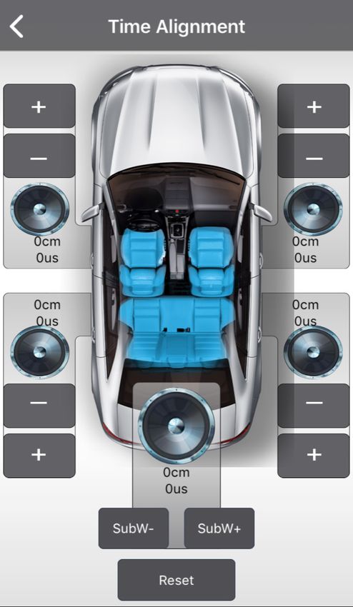
APP INSTALLATION A590DSP                                                                     FUNCTIONS
For Android phones only:
1. Download the A590DSP_V1.0.apk by scan of the QR code or download from the Axton                   Connection to the smart mobile
   website www.axton.de                                                                      Start the app and touch the      “Connect” button. After the connection procedure is
2. Install A590DSP_V1.0.apk to your Android smart phone.                                     done successfully, the app downloads the current settings from the amplifier.
3. Turn on Bluetooth on your mobile and search “A590DSP”, then connect to it with paring
   code 1234.
                                                                                                     Save to Phone
4. Open A590DSP app and click the “Connect” button           to connect your mobile to the
                                                                                             You can save the settings on your smartphone. To do this, press „Save on Phone“ button
   amplifier.
                                                                                                 , enter the desired filename, and confirm with „OK“.
For iOS smart phones only:
1. Visit the Apple AppStore, search for „A590DSP“ and install the app.
2. Turn on Bluetooth.                                                                                Save to AMP
3. Open the app and press the “Connect” button        in order to connect the amp with 		    When you have done the settings, touch the „Save to Amplifier“ button           and chose the
   the app.                                                                                  favorite to transfer the settings to the amplifier. During the saving process do not switch
           Scan to download and                  Scan to download and                        off the amplifier as this may lead to malfunction and/or damage.
           install the app from the              install the app from the
           Apple AppStore                        Axton homepage                                     Load
                                                                                             Shows a list of files saved on the smartphone. Touch the desired setup to load. If you
 APP INSTALLATION A540DSP                                                                    now want to save the loaded setup permanently on the amp, press „Save to Amplifier“
                                                                                             button     .
For Android phones only:
1. Download the A540DSP_V1.0.apk by scan of the QR code or download from the Axton
   website www.axton.de                                                                             Favorites
2. Install A540DSP_V1.0.apk to your Android smart phone.                                     Press the star button      at the top right, and select one of the favorites 1 – 5.
3. Turn on Bluetooth on your mobile and search “A540DSP”, then connect to it with paring
   code 1234.                                                                                UI: Connecting

4. Open A540DSP app and click the “Connect” button           to connect your mobile to the
   amplifier.
For iOS smart phones only:
1. Visit the Apple AppStore, search for „A540DSP“ and install the app.
2. Turn on Bluetooth.                                                                                                                                                        Favorites:
                                                                                                                                                                             Star button
3. Open the app and press the “Connect” button        in order to connect the amp with 		                                                                                    top right
   the app.
          Scan to download and                   Scan to download and
          install the app from the               install the app from the
          Apple AppStore                         Axton homepage

 BLUETOOTH AUDIO STREAMING
                                                                                              Start the app
Open the Bluetooth settings on your smartphone and search for „BT Audio“ device. Press        and touch the
“connect” to get the amp paired with your mobile. When you start playing music on your        ”Connect”
                                                                                              button
mobile, the amp automatically mute the signal from your car stereo. Please note that you
then also cannot hear any warnings or navigation notes from your car stereo.

                                          –8–                                                                                           –9–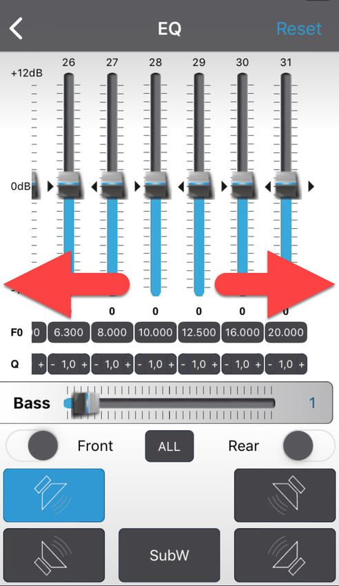
If required, you can choose independent
                                                                      equalizer preferences for the front and
        EQ Settings                                                   rear channels and even for each channel
In the EQ menu you can build your sound                               separately. Simply use the slider Front or
according to your settings. Depending on                              Rear. When you want to do one setting for
the grade of required accuracy, you can                               all channels (w/o sub) just press the “all”
chose between a 10 and a 31 band para-                                button       .
metric equalizer.
                                                                      To reset all settings to „0“, press the
Swipe to the right/ to the left to get to the                         „Reset“ button         in the EQ menu. If
bands outside of the screen area.                                     you just want to try out the presets and
                                                                      then go back to your personal preferences,
                                                                      exit without saving the app, and then
                                                                      restart. The app will then load your saved
                                                                      preferences from the amplifier.

                                                         EQ Setting
                                                                                                                         EQ Setting

In the line „f0“ tap on the band you want to                          Dynamic Bass
adjust. A pop-up window appears to enter                              Located in the EQ menu, the “Bass” slider
the value of the center frequency you want.                           is a very effective way to increase bass per-
Confirm with „Ok“         .                                           formance without overloading the speakers.
                                                                      Level at “0” = no Dynamic Bass function
In the line „Q“ tap on the band you want to                           active.
adjust. A pop-up window appears to enter                              Level at “1” to “20” = the higher the value
the value of the quality factor you want.                             the higher the bass increasing. Simulta-
Confirm with „Ok“         . Instead you can                           neously a strong subsonic filter is enabled
also touch “-“ or “+” to adjust the Q factor in                       to protect the speakers from deepest bass
0.1 steps.                                                            frequencies to avoid damage to them.
The quality factor (Q factor) determines the
effect of the EQ filter (bandwidth) on the
frequency band around the chosen center                               Dynamic Bass:
frequency f0.                                                         The „Bass“ slider
                                                                      offers the bass level
Example1: f0 = 1000 Hz                                                without overloading
desired bandwidth of EQ filter = 1000 Hz                              the speakers.
(i.e. 500 Hz – 1500 Hz) Q = 1
Example2: f0 = 1000 Hz
desired bandwidth of EQ filter = 200 Hz
(i.e. 900 Hz – 1100 Hz) Q = 5

Q factors from 0.3 to 9.9 are possible.
                                                     EQ Setting                                                          EQ Setting

                                                – 10 –                                                          – 11 –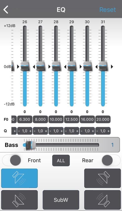
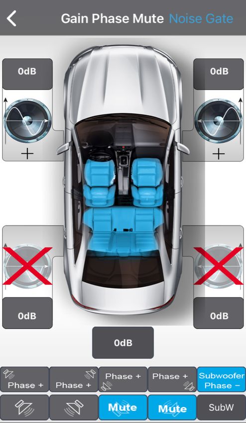
Gain Phase                                                       Crossover
In this menu you can make the following                           In this menu you can assign a frequency
settings for each individual channel: sound                       band to the connected speakers that cor-
level, mute and phase. The sound level set-                       responds to their recommended operat-
tings are made in the field above and under                       ing range. You can chose to adjust each
the respective speaker icons.                                     channel separately, combine front and rear
                                                                  speakers and also all speakers together.
In the lower area of the menu in the top line
are the icons for setting the phase. From
                                                                  In the left half of the diagram you can set
left to right: Front left, Front right, Rear left,
                                                                  the break frequency of the high pass filter
Rear right, Subwoofer.
                                                                  as well as its slope. In the right half are the
In the bottom line are the icons for setting                      break frequency and slope of the low pass
the mute switch. From left to right: Front                        filter. The blue line shows the set slope of
left, Front right, Rear left, Rear right, Sub-                    the filter. „Bypass“ means that the signal is
woofer.                                                           unfiltered and contains all frequencies.
When you have done the settings, go back                          The filter settings also apply to the corre-
to the main menu, and touch the „Save                             sponding preamp outputs.
to Amplifier“ button        to transfer the
settings to the amplifier. During the sav-                        When you have done all settings, go back
ing process do not switch off the amplifier                       to the main menu, and touch the „Save
as this may lead to malfunction and/or                            to Amplifier“ button       to transfer the
damage. You can also save the settings on                         settings to the amplifier. During the saving          Crossover
your smartphone. To do this, press „Save                          process do not switch off the amplifier as
on Phone“         , and enter the desired                         this may lead to malfunction and/or dam-
filename.                                                         age. You can also save the settings on your
                                                                  smartphone. To do this, press the „Save on
                                                                  Phone“ button       , and enter the desired
Noise Gate                                                        filename.
In the upper right corner of the GAIN menu
you can find the Noise Gate function. It’s a
dedicated to reduce the back ground noise
of the head unit. If back ground noise of
the head unit is audible, increase the Noise
Gate level by sliding to the left until you
cannot listen the noise anymore.

      Noise Gate
      function top right

                                                     Gain Phase

                                                – 12 –                                                         – 13 –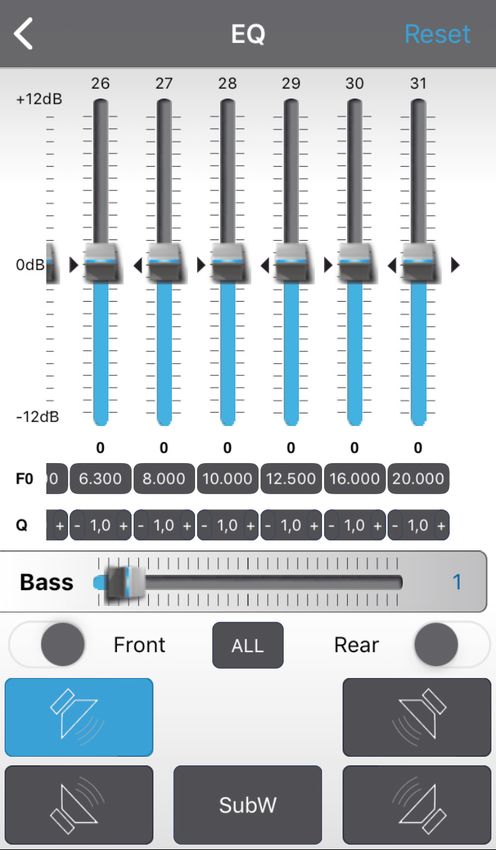
WARRANTY CONDITIONS + LIMITATIONS
       Time Alignment
                                                                     Dear customer
Press the „Time Alignment“ button to go
                                                                     Please read the warranty specifications below carefully.
to the menu. In this menu you can apply a                            Should your AXTON amplifier require warranty service, please return it to the retailer from whom it
time delay to the speaker signal to simulate                         was purchased or the distributor in your country. Do not send any product to AXTON. Should you
an ideal listening position. Note the                                have difficulty in finding an authorized AXTON service center, details are available from your local
distance between your listening position                             distributor.
and each speaker. Choose the most distant                            This AXTON amplifier is fully warranted against defective materials or workmanship for a period of
speaker as the reference for the other                               two years from date of purchase at retail to the original buyer. Warranty work will not be carried out
speakers.                                                            unless this warranty certificate is presented fully completed with serial number, purchaser‘s address,
                                                                     purchasing date and dealer stamp together with the original sales slip and either an authorized deal-
                                                                     er‘s confirmation of installation or authorized dealer‘s installation approval!

                                                                     This warranty does not cover any damage due to:
                                                                     1. Unauthorized or unapproved installation, incorrect audio or mains connection(s).
                                                                     2. Defects caused by exposure of the amplifier to humidity, water and organic fluids, prolonged
                                                                        exposure to sun rays or excessive dirt or dust.
Note the distance                                                    3. Mechanical defects caused by accidents, fall or impact.
between your                                                         4. Unauthorized repair attempts and modifications not explicitly authorized by the manufacturer.
listening position
and each speaker.                                                    This warranty is limited to the repair or the replacement of the defective product at the manufacturer‘s
                                                                     option and does not include any other form of damage, whether incidental, consequential or other-
                                                                     wise. The warranty does not cover any transport costs or damages caused by transport or shipment
                                                                     of the product. Any additional or further claims and requirements for compensation of auxiliary com-
                                                                     ponents that have been damaged by the amp in sequence, directly or indirectly, are strictly excluded.
                                                     Time Aligment

With the aid of the following example,                               You can find the warranty slip on page 30.
calculate the values for your speakers:

(FL)     front left is    0.80 m from the listening position
(FR)     front right is   1.40 m from the listening position
(RL)     rear left is     0.50 m from the listening position
(RR)     rear right is    1.30 m from the listening position
(SubW)   subwoofer is     2.00 m from the listening position
Value for FL = SubW – FL → FL = 2.00 – 0.80 m
Value for FR = SubW – FR → FL = 2.00 – 1.40 m
Value for RL = SubW – RL → RL = 2.00 – 0.50 m
Value for RR = SubW – RR → RR = 2.00 – 1.30 m
SubW remains at the value „0“

                                            – 14 –                                                                  – 15 –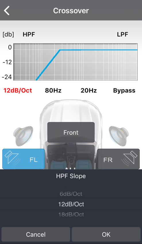
Wir danken Ihnen für den Kauf dieser innovativen AXTON Endstufe.                            SICHERHEITSHINWEISE
Damit Sie die Wiedergabequalität und die Leistungsfähigkeit dieses Verstärkers voll aus-     Bedienen Sie keine Funktion, die Sie während der Autofahrt ablenken könnte.
                                                                                           n
schöpfen können, bitten wir Sie, sich eingehend mit den Möglichkeiten und technischen          Funktionen, welche Ihre besondere Aufmerksamkeit erfordern, dürfen ausschliesslich
Features dieses Verstärkers vertraut zu machen. Lesen Sie deshalb die nachfolgenden            genutzt werden, wenn das Fahrzeug stillsteht. Stellen Sie sicher, dass Sie an einem
Abschnitte sorgfältig durch und bewahren Sie diese Bedienungsanleitung auf.                    sicheren Ort parken, bevor Sie das Gerät bedienen. Es besteht sonst ein hohes
Falls Sie im Anschluss weitergehende Fragen zu den Funktionen oder dem Anschluss               Risiko eines Unfalls.
dieser Enstufe haben, kontaktieren Sie Ihren Händler.                                        Halten Sie die Lautstärke auf einem Level, wo Sie noch Geräusche von aussen
                                                                                           n
                                                                                               wahrnehmen können. Es besteht sonst ein hohes Risiko eines Unfalls.
                                                                                             Öffnen und/oder modifizieren Sie das Produkt nicht. Es besteht sonst ein hohes
                                                                                           n
                                                                                               Risiko eines Unfalls, Feuers oder elektrischen Schlags.
                                                                                             Der Verstärker ist ausschliesslich für Anwendungen in PKW mit einem 12 Volt
                                                                                           n
                                                                                               Bordnetz mit (-) Masse vorgesehen. Es besteht bei anderweitiger Verwendung ein
                                                                                               hohes Risiko eines Unfalls, Feuers oder elektrischen Schocks.
                                                                                             Verwenden Sie für den Masseanschluss keine Mutter oder Befestigungen
                                                                                           n
                                                                                               der Bremse, Lenkung oder des Tanks. Die Nutzung dieser Teile kann die
                                                                                               Sicherheitseinrichtungen des Fahrzeugs deaktivieren oder zu Fehlfunktionen führen.
                                                                                               Es besteht daher ein hohes Risiko eines Unfalls oder Feuers.
                                                                                             Verdecken oder behindern Sie keine Öffnungen oder Ventilatoren. Durch
                                                                                           n
                                                                                               Überhitzung besteht die Gefahr eines Feuers.
                                                                                             Stellen Sie sicher, dass alle Anschlüsse korrekt sind. Es besteht sonst ein hohes
                                                                                           n
                                                                                               Risiko eines Unfalls, Feuers oder elektrischen Schocks.
                                                                                             Halten Sie kleine Objekte, wie zum Beispiel Schrauben und Muttern von
                                                                                           n
                                                                                               Kindern fern. Ein Verschlucken solcher Objekte kann schwerwiegende Folgen für
                                                                                               die Gesundheit haben. Im Fall eines Verschluckens suchen Sie umgehend ärztliche
                                                                                               Hilfe.
                                                                                           n   Trennen Sie vor der Installation den Minus-Pol von der Batterie, um
                                                                                                Verletzungen oder Beschädigungen am Produkt oder Fahrzeug zu vermeiden.

                                         – 16 –                                                                                    – 17 –
TECHNISCHE SPEZIFIKATIONEN A590DSP / A540DSP                                                INSTALLATIONSSCHEMA

                                A590DSP                      A540DSP
 Music Power Output:*           150 W x 4 @ 4/2 Ohm          54 W x 4 @ 4 Ohm
 RMS Power Output:*             76 W x 4 @ 4/2 Ohm           32 W x 4 @ 4 Ohm
 Music Power Output:            100 W x 4 @ 4/2 Ohm          n.a.
 RMS Power Output:              50 W x 4 @ 4/2 Ohm           n.a.
 Wiedergabebereich:             20 Hz ~ 20 kHz               20 Hz ~ 20 kHz
                                                                                                                                                  ORIGINAL CAR SOCKETS
 Audio Sampling Frequenz:       192 kHz                      192 kHz
 Verzerrung:                    1 KHz < 0.001%               1 KHz < 0.001%
 Spannungsbereich:              9 V – 15 V                   9 V – 15 V
 Störabstand:                   > 120 dB                     > 120 dB
 Dynamikumfang:                 > 100 dB                     > 100 dB
 Ruhestrom:                     0 mA                         0 mA                                                                                   HEAD UNIT
 Maximale Stromaufnahme:        20 A                         15 A
 Abmessungen (L x B x H):       185(218**) x 114 x 40 mm     145(177**) x 114 x 40 mm

* Mit zusätzlicher Stromversorgung.
** Inklusive BT Antenne.

 HAUPTMERKMALE
n 4-Kanal Smart Digital Amplifier mit iOS oder Android App kontrollierten Audio DSP
  Funktionen
n DSP-kontrollierter 5-Kanal Vorverstärkerausgang (6 Volt) inklusive Remote-Ausgang          MONTAGEANLEITUNG
  zum Ansteuern zusätzlicher Verstärker
n Bluetooth Audio Streaming mit automatischer Quellenumschaltung                            1. Bevor Sie beginnen, vergewissern Sie sich, dass Sie den Diebstahlcode Ihres
n Plug’N’Play Installation mit optionalen fahrzeugspezifischen Anschlusskabeln                 Autoradios kennen (falls es eine Code-Sperre hat).
n Auto-Turn-On Funktion
                                                                                            2. Entfernen Sie das Radio aus dem Radioschacht. Beachten Sie dabei die Anleitung
                                                                                               des Herstellers.
 FUNKTIONEN & EINSTELLMÖGLICHKEITEN                                                         3. Suchen Sie sich einen geeigneten Platz für den A590DSP und A540DSP
n Frei einstellbare 3-Wege Aktivweiche : Hoch-/Tief-/Band-/Bypass mit 6/12/18/24 dB/           und verbinden Sie das beiliegende Kabel mit dem Verstärker (oder mit einem optional
  Oct. Flankensteilheit für Front, Rear und Subwoofer Kanäle                                   erhältlichen fahrzeugspezifischen Axton-Anschlusskabel).
n Laufzeitkorrektur in cm für Front-, Rear- und Subwoofer-Kanäle (0 – 420 cm)               4. Nur A590DSP: Für eine höhere Ausgangsleistung gehen sie wie folgt vor:
n Gain, Phasenschalter und Mute Funktion pro Kanal                                             Verlegen Sie ein 10 mm2 Kabel von der Batterie zum (B+)-Anschluss des
n Frei konfigurierbarer 10 oder 31-Band parametrischer Equalizer für alle einzelnen Front      Verstärkers. Sichern Sie das Batteriekabel mit einer entsprechenden Sicherung ab.
  und Rear Lautsprecher                                                                        Der Sicherungshalter darf höchstens 30 cm vom Batteriepol entfernt sein.
n Frei konfigurierbarer 5-Band parametrischer Equalizer für den Subwoofer-Kanal                Verbinden Sie ein Minuskabel gleichen Querschnitts mit dem (B-)-Anschluss und der
n Speicherplätze für eigene Settings: 5 auf dem Verstärker, unlimitiert auf dem                Fahrzeugmasse. Achten Sie darauf, dass die Kontaktfläche sauber und leitfähig ist.
  Smartphone
n Dynamic Bass Funktion für kraftvolle Performance ohne Subwoofer                           5. Verbinden Sie das Anschlusskabel mit dem Radio.
n Noise Gate Funktion zum Reduzieren des Grundrauschens des Radios.                         6. Installieren Sie das Radio wieder im Radioschacht gemäss Herstelleranleitung.

                                          – 18 –                                                                                    – 19 –
ANSCHLUSSSCHEMA A590DSP ANSCHLUSSSCHEMA A540DSP
Wenn Sie nur die DSP Funktionen des A590DSP in Verbindung mit einem separaten Wenn Sie nur die DSP Funktionen des A540DSP in Verbindung mit einem separaten
Installation Diagram
Verstärker verwenden möchten, verrbinden Sie den Line Out des A590DSP mit den RCA Verstärker verwenden möchten,USER
verrbinden
MANUAL
Sie den Line Out des A540DSP mit den RCA
Eingängen des separaten Verstärkers. Eingängen des separaten Verstärkers.
SPEAKER SPEAKER
Wire Diagram
20 20
20
FR+in RR-out
FR-in RR+out
FL+in RL-out
FL-in RL+out
1* ACC-in 11 GND RL+in
RL-in
RR+in
FR-out
FR+out
FL-out
1* ACC-in 11 GND
Installation Diagram
RR-in FL+out
GROUND (-) BATTERY (+) FUSE
2* Rem-out 12 +B +B
GND
Model No.: MDA-100 2* Rem-out 12 +B
ANTENNA USER MANUAL SPEAKER REMOTE POWER ANTENNA
3 RR-in 13 FL+out 3 RR-in 13 FL+out
SPEAKER IMPEDANCE
4 RR+in 14 FL-out 4 RR+in 14 FL-out
5 RL-in 15 FR+out 5 RL-in 15 FR+out
Wire Diagram
6 RL+in 16 FR-out 6 RL+in 16 FR-out
7 FL-in 17 RL+out 7 FL-in 17 RL+out
20
FR+in RR-out
FR-in RR+out
8 FL+in 18 RL-out 8 FL+in 18 RL-out
FL+in RL-out
FL-in RL+out
RL+in FR-out
RL-in FR+out
RR+in
RR-in
FL-out
FL+out
+B
9 FR-in 19 RR+out 9 FR-in 19 RR+out
GND
Model No.: MDA-100
FRONT/REAR FRONT/REAR
FRONT/REAR SPEAKER REMOTE POWER 10 FR+in 20 RR-out LINEOUT LINE IN 10 FR+in 20 RR-out
LINEOUT
1* In seltenen Fällen wird die Auto-Turn-On Funktion mit älteren Autoradios nicht arbeiten. Falls Sie auf dieses 1* In seltenen Fällen wird die Auto-Turn-On Funktion mit älteren Autoradios nicht arbeiten. Falls Sie auf dieses
Problem treffen, stecken Sie bitte das mitgelieferte „ACC-IN“ Kabel in den Anschlussstecker und verbinden Problem treffen, stecken Sie bitte das mitgelieferte „ACC-IN“ Kabel in den Anschlussstecker und verbinden
es mit dem ACC/Amp Remote Anschluss des Radios oder einem anderen Kabel, welches +12 V liefert, es mit dem ACC/Amp Remote Anschluss des Radios oder einem anderen Kabel, welches +12 V liefert,
sobald das Radio eingeschaltet ist. Wählen Sie zweitens „REMOTE TURN ON“ auf dem Remoteschalter. sobald das Radio eingeschaltet ist. Stellen Sie den Remoteschalter auf „REMOTE TURN ON“.
2* REM-Out: Schliessen Sie dieses Kabel an den Remote-Eingang eines separaten Verstärkers an, zum 2* REM-Out: Schliessen Sie dieses Kabel an den Remote-Eingang eines separaten Verstärkers an, zum
Beispiel einen Monoblock für einen Subwoofer. Beispiel einen Monoblock für einen Subwoofer.
DIMENSIONS A590DSP DIMENSIONS A540DSP
Model No.: MDA-100
185 mm 145 mm
USER MANUAL
POWER PROTECT
(20 A)
FUSE
4Ω
REMOTE TURN ON
SIGNAL TURN ON
2Ω
A590DSP
SUB R
SUB L
BATT.
SPEAKER LEVEL
INPUT/OUTPUT
POWER IN
LINE OUT
114 mm
114 mm
RR
RL
GND
Installation Diagram
Wire
FL
FR
Diagram
FR
FL
RR+out
FR+out
RL+out
FL+out
RR-out
FR-out
RL-out
FL-out
20
GND
SPEAKER
INPUT/OUTPUT
GND
RR+in
FR+in
RL+in
+B
FL+in
RR-in
FR-in
RL-in
FL-in
LINE OUT
RL
RR
LEVEL
BATT.
RR+in
FR+in
RL+in
FL+in
RR-in
FR-in
RL-in
RR+out
FL-in
FR+out
RL+out
FL+out
RR-out
FR-out
RL-out SIGNAL TURN ON
FL-out
A590DSP
GND
+B
Installation Diagram
SUB R
SUB L
20
REMOTE TURN ON
POWER PROTECT
Wire Diagram
2Ω
ANT
4Ω
40 mm
40 mm
USER MANUAL
– 20 – – 21 –
Model No.: MDAAPP INSTALLATION A590DSP FUNKTIONEN
Nur für Android Smartphones: Verbinden mit dem Smartphone
1. Laden Sie die A590DSP_V1.0.apk App über den QR-Code oder von der Axton Starten Sie die App und drücken Sie den “Connect” Button . Nach dem
Webseite www.axton.de herunter. Verbindungsaufbau lädt die App automatisch die aktuellen Einstellungen des Verstärkers.
2. Installieren Sie A590DSP_V1.0.apk auf Ihrem Android Smartphone.
3. Schalten Sie Bluetooth auf Ihrem Smartphone ein und suchen Sie “A590DSP”.
Koppeln Sie die Geräte mit dem Pairing-Code 1234. Save to Phone
4. Öffnen Sie die A590DSP App und berühren Sie den “Connect” Button , um den Sie können die Einstellungen auch auf Ihrem Smartphone speichern. Drücken Sie dazu auf
Verstärker mit der App zu verbinden. „Save on Phone“, geben den gewünschten Dateinamen ein und bestätigen Sie mit „OK“.
Nur für iOS Smartphones:
1. Gehen Sie in den Apple AppStore, suchen Sie nach „A590DSP“ und laden Sie die
App auf Ihr Smartphone. Save to AMP
2. Aktivieren Sie Bluetooth. Berühren Sie den „Save to Amp“ Button, um die Einstellungen auf den Verstärker zu
3. Öffnen Sie die A590DSP App und berühren Sie den “Connect” Button , um den übertragen. Wählen Sie dazu einen der fünf Speicherplätze aus. Während des Speichervor-
Verstärker mit der App zu verbinden. gangs darf der Verstärker nicht abgeschaltet werden, da dies zu Fehlfunktionen und/oder
Schäden führen kann.
Scannen zum Download Scannen zum Download
und zur Installation der und zur Installation der APP Load
APP aus Apple AppStore von der Axton Homepage
Zeigt eine Liste der auf dem Smartphone gespeicherten Dateien. Das gewünschte Setup
antippen und es wird geladen. Soll das geladene Setup nun permanent auf dem Verstär-
APP INSTALLATION A540DSP ker gespeichert werden, drücken Sie im Anschluss auf „Save to Amp“ Button
Nur für Android Smartphones:
1. Laden Sie die A540DSP_V1.0.apk App über den QR-Code oder von der Axton Favoriten
Webseite www.axton.de herunter. Drücken Sie den Stern-Button oben rechts und wählen Sie einen der Favoriten 1 – 5.
2. Installieren Sie A540DSP_V1.0.apk auf Ihrem Android Smartphone.
3. Schalten Sie Bluetooth auf Ihrem Smartphone ein und suchen Sie “A540DSP”.
Koppeln Sie die Geräte mit dem Pairing-Code 1234.
4. Öffnen Sie die A540DSP App und berühren Sie den “Connect” Button , um den UI: Connecting
Verstärker mit der App zu verbinden.
Nur für iOS Smartphones:
1. Gehen Sie in den Apple AppStore, suchen Sie nach „A540DSP“ und laden Sie die
App auf Ihr Smartphone.
2. Aktivieren Sie Bluetooth. Favoriten:
Stern-Button
3. Öffnen Sie die A540DSP App und berühren Sie den “Connect” Button , um den oben rechts
Verstärker mit der App zu verbinden.
Scannen zum Download Scannen zum Download
und zur Installation der und zur Installation der APP
APP aus Apple AppStore von der Axton Homepage
BLUETOOTH AUDIO STREAMING
Starten Sie
Öffnen Sie die Bluetooth Einstellung auf Ihrem Smartphone und suchen Sie das Gerät „BT die App und
Audio“. Drücken Sie „Verbinden“ um Ihr Smartphone mit dem Verstärker zu koppeln. Wenn drücken Sie
Sie nun die Musikwiedergabe starten, wird das Radiosignal automatisch stummgeschaltet. den ”Connect
Button”
Beachten Sie bitte, dass Sie während der BT Audio Wiedergabe auch keine Warnhinweise
oder Navigationsdurchsagen des Radios hören.
– 22 – – 23 –Sie können bei Bedarf für die Front und
EQ Setting Rückkanäle unabhängige Equalizer Ein-
stellungen wählen. Drücken dafür einfach
Im Equalizer Menü können Sie den Klang auf den Slider Front oder Rear. Die App
an die Gegebenheiten des Fahrzeuges an- kopiert nun wahlweise die Werte von FL
passen. Abhängig vom Grad der erforder- oder FR. Möchten Sie identische Einstel-
lichen Genauigkeit, wählen Sie zwischen lungen für sämtliche Kanäle vornehmen,
dem 10-Band oder dem 31-Band para- drücken Sie auf „ALL“ .
metrischen EQ. Mit diesem EQ sind Sie in
der Lage, den Frequenzgang punktgenau Um sämtliche Einstellungen auf „0“ zu-
zu korrigieren. rückzusetzen, drücken Sie „Reset“
oben rechts. Für den Fall, dass Sie die
Wischen Sie nach rechts bzw. Links, um Presets nur ausprobieren und danach
die Frequenzbänder außerhalb des Dis- wieder zu Ihren persönlichen gelangen
plays zu erreichen. wollen, beenden Sie ohne zu speichern
die App und starten Sie sie neu. Die App
lädt dann Ihre gespeicherten Einstellungen
vom Verstärker.
EQ Setting EQ Setting
Dynamic Bass
Tippen Sie in der Zeile „f0“ auf das gewün-
schte Band. Ein Pop-Up Fenster erscheint, Der „Bass“-Regler bietet eine grossartige
wo Sie den Wert der gewünschten Mit- Möglichkeit für mehr Bass ohne die Laut-
tenfrequenz eintragen und mit „Ok“ sprecher zu stark zu überlasten.
bestätigen. Tippen Sie in der Zeile „Q“ auf Level „0“ = keine Dynamic Bass Funktion
das gewünschte Band. Ein Pop-Up Fenster aktiv
erscheint, wo Sie die gewünschte Güte Level „1“ bis „20“ = je höher der Wert, umso
eintragen und mit „Ok“ bestätigen. grösser die Bassverstärkung. Gleichzeitig
Die Güte bestimmt die Auswirkungen des wird ein Subsonicfilter aktiviert, der die
EQ-Filters (Bandbreite) der gewählten Lautsprecher vor sehr tiefen Frequenzen
Mittenfrequenz f0 auf das umliegende schützt.
Frequenzband.
Dynamic Bass:
Beispiel 1: f0 = 1000 Hz “Bass” Regler für
mehr Bass ohne
gewünschte Bandbreite des EQ-Filters =
die Lautsprecher zu
1000 Hz (also 500 Hz – 1500 Hz) stark zu überlasten.
Q=1
Beispiel 2: f0 = 1000 Hz
gewünschte Bandbreite des EQ-Filters =
200 Hz (also 900 Hz – 1100 Hz)
Q=5
Es sind Q-Werte von 0,3 bis 9,9 möglich. EQ Setting EQ Setting
– 24 – – 25 –Gain Phase Crossover
In diesem Menü können für jeden einzel- In diesem Menü können Sie den ange-
nen Kanal folgende Einstellungen vorge- schlossenen Lautsprechern ein Frequenz-
nommen werden: Pegel, Stummschaltung band zuweisen, welches deren empfohle-
und Phase. Die Einstellungen ändern Sie nen Einsatzbereich entspricht. Sie können
direkt im Feld über dem jeweiligen Laut- die Einstellungen für jeden Kanal einzeln,
sprecher-Icon. Front und Rear paarweise oder alle Kanäle
zusammen vornehmen.
Im unteren Bereich des Menüs befinden
sich in der oberen Zeile die Icons zum Ein-
stellen der Phase. Von links nach rechts: In der linken Hälfte des Diagramms wählen
Front links, Front rechts, Hinten links, Sie die Flankensteilheit und die Einsatz-
Hinten rechts, Subwoofer. frequenz des Hochpassfilters HPF, in der
rechten Hälfte die gleichen Parameter für
In der unteren Zeile befinden sich die Icons den Tiefpassfilter LPF. Die blaue Linie zeigt
zum Einstellen der Stummschaltung. Von exemplarisch die eingestellte Flankensteil-
links nach rechts: Front links, Front rechts, heit des Filters. „Bypass“ bedeutet, dass
Hinten links, Hinten rechts, Subwoofer. das Signal ungefiltert alle Frequenzen
Wenn Sie die Einstellungen abgeschlossen enthält. Die Einstellungen der Filter gelten
haben, kehren Sie in das Hauptmenü zu- auch für die entsprechenden Vorverstärker-
rück und berühren Sie den „Save to Amp“ ausgänge.
Button , um die Einstellungen auf den
Verstärker zu übertragen. Während des Gain Phase Crossover
Wenn Sie die Einstellungen abgeschlossen
Speichervorgangs darf der Verstärker nicht
haben, kehren Sie in das Hauptmenü zu-
abgeschaltet werden, da dies zu Fehlfunk-
rück und berühren Sie den „Save to Amp“
tionen und/oder Schäden führen kann. Sie
Button , um die Einstellungen auf den
können die Einstellungen zusätzlich auf
Verstärker zu übertragen. Während des
Ihrem Smartphone speichern. Drücken Sie
Speichervorgangs darf der Verstärker nicht
dazu „Save on Phone“ und geben Sie
abgeschaltet werden, da dies zu Fehlfunk-
den gewünschten Dateinamen ein.
tionen und/oder Schäden führen kann. Sie
können die Einstellungen zusätzlich auf
Noise Gate Ihrem Smartphone speichern. Drücken Sie
dazu „Save on Phone“ und geben Sie
In der oberen rechten Ecke des GAIN-
den gewünschten Dateinamen ein.
Menüs befindet sich die Noise Gate
Funktion. Sie ist dazu gedacht, mögliches
Grundrauschen des Radios zu reduzieren.
Falls ein Grundrauschen hörbar ist, schie-
ben Sie den Regler nach links, bis es nicht
mehr oder nur noch kaum hörbar ist.
Noise Gate
Funktion oben
rechts
Gain Phase
– 26 – – 27 –GARANTIE-BESTIMMUNGEN + EINSCHRÄNKUNGEN
Time Alignment
Sehr geehrter Kunde,
In diesem Menü sind Sie in der Lage,
Wir bitten Sie die untenstehenden Garantie-Bestimmungen genau durchzulesen.
das Signal der Lautsprecher zeitlich zu Sollten Sie für Ihren Verstärker Garantie-Leistungen beanspruchen, wenden Sie sich bitte direkt an
verzögern, um eine ideale Hörposition zu den Händler, bei dem Sie das Gerät gekauft haben. Bitte senden Sie keine Geräte an AXTON. Bei
simulieren. Schwierigkeiten, ein geeignetes AXTON Service-Center zu finden, erhalten Sie bei Ihrem jeweiligen
Landes-Vertrieb weitere Informationen.
Notieren Sie sich die Distanzen von Ihrer Der Hersteller gewährleistet auf diesen AXTON Verstärker für den Fall von Material- oder
Hörposition zu jedem angeschlossenen Herstellungsfehlern zwei Jahre Garantie, ab Kaufdatum in Fachhandel an den Erstkäufer. Garantie-
Lautsprecher. Der am weitesten entfernte Ansprüche können nur mit einer korrekt und vollständig ausgefüllten Garantie-Karte zusammen mit
Lautsprecher ist die Basis, an der sich die dem Original-Kaufbeleg geltend gemacht werden.
anderen Lautsprecher orientieren müssen.
Nicht durch Gewährleistung oder Garantie des Herstellers abgedeckt, sind Schäden infolge von:
1. Nicht-autorisiertem bzw. ungeprüftem Selbst-Einbau mit in Folge inkorrekten Audio- und/
oder Stromanschlüssen.
2. schädliche Einwirkung von Feuchtigkeit, Wasser, organische Flüssigkeiten, übermässiger
Notieren Sie sich Hitze oder Sonneneinstrahlung und starker Verschmutzung.
die Distanzen von 3. Mechanischer Beschädigung durch Fall, Stoss oder Unfall.
Ihrer Hörposition zu 4. Schäden durch nicht autorisierte Reparaturversuche oder nicht durch den Hersteller aus-
jedem angeschloss- drücklich autorisierte Modifikationen.
enen Lautsprecher
Die Garantie dieses Produkts bleibt in jedem Fall auf die Reparatur bzw. den Ersatz (Entscheidung
durch Hersteller) des jeweiligen AXTON Produkts beschränkt. Schäden durch unsachgemässe
Verpackung und daraus resultierende Transportschäden werden nicht durch diese Garantie gedeckt.
Jeder über diese Garantie-Erklärung hinausgehende Anspruch und jede Haftung für direkte oder
Time Aligment
indirekte Folgeschäden werden ausdrücklich abgelehnt.
Berechnen Sie anhand des folgenden Beispiels Sie finden die Garantiekarte auf Seite 30.
die Werte für Ihre Lautsprecher:
(FL) Front Links ist 0,80 m von der Hörposition entfernt
(FR) Front Rechts ist 1,40 m von der Hörposition entfernt
(RL) Hinten Links ist 0,50 m von der Hörposition entfernt
(RR) Hinten Rechts ist 1,30 m von der Hörposition entfernt
(SubW) Subwoofer ist 2,00 m von der Hörposition entfernt
Wert für FL = SubW – FL → FL = 2,00 – 0,80 m
Wert für FR = SubW – FR → FR = 2,00 – 1,40 m
Wert für RL = SubW – RL → RL = 2,00 – 0,50 m
Wert für RR = SubW – RR → RR = 2,00 – 1,30 m
SubW bleibt bei Wert „0“
– 28 – – 29 –WARRANTY SLIP / GARANTIE-KARTE
Model name: A590DSP A540DSP
Date of purchase / Kaufdatum:
Your name / Ihr Name:
Your address / Ihre Adresse:
City / Stadt / Ville:
ZIP or Postal Code / PLZ:
Country / Land:
Your Dealer:
A590DSP 10R-0510392
(EN) Hereby, ACR Brändli + Vögeli AG declares that the type of radio equipment A590DSP/A540DSP
complies with the 2014/53/EU Directive. The full text of the EU Declaration of Conformity is available
at the following Internet address: http://www.acr.ch/en/ (see link “Product Conformity Documents” in
A540DSP 10R-0510263 the footer are of the page).
(DE) Hiermit erklärt ACR Brändli + Vögeli AG, dass der Funkanlagentyp A590DSP/A540DSP der
Richtlinie 2014/53/EU entspricht. Der vollständige Text der EU-Konformitätserklärung ist unter der
folgenden Internetadresse verfügbar: http://www.acr.ch/ (siehe Link „Dokumente zur Produktkonform-
ität“ im Fussbereich).
(FR) ACR Brändli + Vögeli AG déclare par la présente que le type d’équipement radio A590DSP/
A540DSP est conforme à la directive 2014/53/UE. Le texte complet de la déclaration de conformité
EU Legal Representative: ACR S & V GmbH ∙ Industriestr. 35 ∙ D-79787 Lauchringen ∙ Germany
UE est disponible à l’adresse Internet suivante: http://www.acr.ch/en/ (voir le lien “Documentation de
Exclusive Distributor for Europe: ACR AG ∙ Bohrturmweg 1 ∙ CH-5330 Bad Zurzach ∙ Switzerland conformité du produit” dans le pied de page).
– 30 –Rev. D
You can also read