ACCENT 800 FLAME EFFECT SPACE HEATER - INSTALLATION & OPERATING MANUAL The Real Flame Accent 800 space heater is suitable to be installed into
←
→
Page content transcription
If your browser does not render page correctly, please read the page content below
ACCENT 800 FLAME EFFECT
     SPACE HEATER
 INSTALLATION & OPERATING MANUAL

 The Real Flame Accent 800 space heater is suitable to be installed into a
                         frame out installation.
           Designed to operate on Natural gas and ULPG gas.
                         Approval no.GMK 10528

                               VERSION 5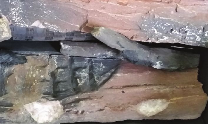
WARRANTY INFORMATION
    The benefits provided to you under the following warranty are in addition to any other rights and remedies available to
    you under the law.
    1. Warranty
    If:
    (a)   during the first 15 years from the date of purchase (Firebox Warranty Period), there is a defect in the firebox of the
          Gas Burner; or
    (b)   during the first 2 years from the date of purchase (Parts Warranty Period), there is a defect in the gas valves or
          other parts of the Gas Burner,
          due to improper workmanship or material, Glen Dimplex will replace or repair the Gas Burner without charge. Any
          replacement product is warranted only for the time remaining on the original Firebox Warranty Period or the Parts
          Warranty Period as relevant.
    2. Registration
          You must register to receive the benefit of this warranty by completing the warranty registration on our website
          (www.realflame.com.au) or completing and mailing the attached registration card within 30 days of purchase of
          your Gas Burner (or, if the Gas Burner is fitted to a new home, within 30 days of the date of settlement of purchase
          of such new home).
    3. Exclusions
          Glen Dimplex is not obliged to replace or repair the Gas Burner under clause 1 if:
    (a)   it has been improperly stored, installed, connected, used, operated or repaired, or damaged, abused, tampered
          with, altered (without our written approval), or not maintained in strict accordance with our installation and
          operating instructions; or
    (b)   it has been installed in an outdoor setting.
    4. Limit of Liability
          The warranty provided under this warranty is limited to replacement or repair of the Gas Burner only, at our option.
          To the extent permitted by law, Glen Dimplex excludes liability for consequential loss or any other loss or damage
          caused to property or persons arising from any cause whatsoever, and damage arising from normal wear and tear.
    5. Claiming under the Warranty
          In order to claim under this warranty you must, within the Firebox Warranty Period or the Parts Warranty Period
          (as relevant), contact Glen Dimplex, providing the original proof of purchase and the details below:

    Supplier Name___________________________________________________________________________
    Date Of Purchase / settlement of property if new home _________________
    Model / Serial Number_______________________
    This warranty does not cover the cost of claiming under the warranty or transporting the Real Flame Gas Burner to and
    from the supplier.

    Our goods come with guarantees that cannot be excluded under the Australian Consumer Law. You are entitled to a
    replacement or refund for a major failure and for compensation for any other reasonably foreseeable loss or damage.
    You are also entitled to have the goods repaired or replaced if the goods fail to be of acceptable quality and the failure
    does not amount to a major failure.

    If you would like to speak to someone about your Gas Burner or claiming under this warranty, please contact the
    Service Warranty Desk on 1300 554 155.

    Glen Dimplex Australia Pty Ltd ACN 69 118 275 460
    Head Office: 1340 Ferntree Gully Road, Scoresby 3179
    Telephone: (03) 8706 2000 Facsimile: (03) 876 2001

2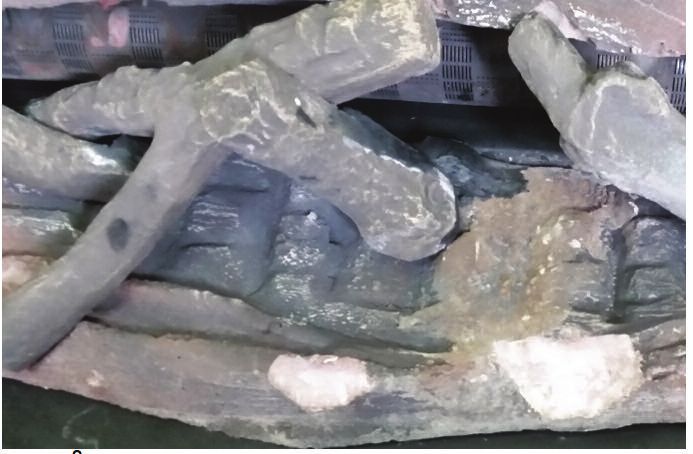
WARNING
The Accent 800 space heater has a primary safety glass fitted in front of the glass door. This safety glass is
fitted to this appliance to reduce the risk of injury from burns and at no time should this glass be
permanently removed.
For protection of young children or the infirm, a secondary guard is required.
The appliance is not intended for use by persons (including children) with reduced physical, sensory or
mental capabilitites, or lack of experience and knowledge, unless they have been given supervision or
instruction concerning use of the appliance by a person responsible for their safety. Children should be
supervised to ensure that they do not play with the appliance.

WARNING
The outer glass panel gets extremely hot! Precaution should be taken and young children
supervised at all times when heater is operating.

INSTALLATION NOTICE
   The installation of this appliance is only to be carried out by an authorised person in accordance
   with the Manufacturer’s Instructions, local gas fitting regulations, AS/NZS5601.1-2013 installation
   code for gas burning appliances and any other relevant statutory regulations.
   Do not modify this appliance.
   In all cases the installation of this appliance shall meet the requirements as set out in
   AS/NZS5601.1-2013.
   Do not install in a fireplace as a Type 1 installation.

   NOTE: A slight smell may be apparent for the first few hours of use. This is due to the heat resistant
   paint curing. It is recommended to open windows in the room for the first lighting of the fire. In some
   instances a slight discolouration may occur inside the firebox. This is a normal condition and is not
   covered by warranty.

IMPORTANT SAFETY NOTICE
   DO NOT PLACE ARTICLES ON OR AGAINST THIS APPLIANCE.
   DO NOT USE OR STORE FLAMMABLE MATERIALS IN OR NEAR THIS APPLIANCE.
   DO NOT SPRAY AEROSOLS IN THE VICINITY OF THIS APPLIANCE WHILST IT IS IN OPERATION.
   CARE MUST BE TAKEN TO ENSURE THAT ANY RETURN AIR REGISTER OR EXHAUST SYSTEM
   DOES NOT ADVERSLEY AFFECT THE OPERATION OF THE APPLIANCE OR DRAUGHT OF
   CHIMNEY OR FLUE.

SERVICING
It is recommended you service your gas fire every 2 years as a minimum.

CORD REPLACEMENT
Electrical cord replacement must be undertaken by qualified and trained personnel only.

   APPLIANCE IS DESIGNED TO OPERATE WITH LUMINOUS FLAMES.                                                        3
   MAY EXHIBIT SLIGHT CARBON DEPOSIT.
CONTENTS
       Contents .................................................................................................................4
       Data Plate ...............................................................................................................5
       Dimensions .............................................................................................................5
       Installation Instructions ...........................................................................................6
       Flue Termination .....................................................................................................8
       Installation Instructions
              Setup with external wall mounted fan terminal...............................................9
              Setup with rooftop termination......................................................................14
       Timber Frame Installation .....................................................................................18
       Media Installation..................................................................................................19
       Commissioning Procedure....................................................................................23
       Operation - User Instructions................................................................................24
       Troubleshooting ....................................................................................................29
       Remote Control.....................................................................................................30
       Wiring Diagram .....................................................................................................31
       Conversion Details................................................................................................32
       Parts List...............................................................................................................33
       Real Flame Contact Information ...........................................................................36

4
DATA PLATE (Affixed to the base of the unit for reference to gas pressure & consumption)
 MODEL                ACCENT 800

 GAS TYPE         INJECTOR SIZE                       TPP                  N.G.C. (Mj/hr)

 Natural Gas      1 X 2.50mm            0.90kPa High / 0.47kPa Low        26.5 High/19 Low

 ULPG             1 X 1.38mm            2.60kPa High / 1.60kPa Low        24.5 High/19 Low

DIMENSIONS

         7                                       7

                               804

    65
                                                     659

                                                                                             5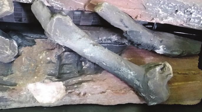
INSTALLATION INSTRUCTIONS
        LOCATION
        Select a location where the fire can be supervised during operation.
        An electrical isolation switch must be fitted at the appliance or on an adjacent wall to allow for
        emergency shutdown and maintenance.
        Installation must meet Australian gas codes AS/NZS 5601.

        INSTALLATION CLEARANCES – Clearances from combustible materials
        Floor            0mm
        Sides            5mm
        Top              5mm
        Flue outer       25mm
        Front            250mm
        Back             25mm

        INSTALLATION CODES
        Note appliance gas type – Natural gas or ULPG. Should the appliance be the incorrect gas type
        please contact the supplier for the conversion kits available for the appliance.
        Installers – Please ensure the installation and instruction manuals supplied with this appliance are
        supplied to the customer and the customer is trained on how to operate the appliance correctly.
        Do not modify the appliance.
        Do not exceed maximum rated pressures.
        Appliance must be installed as per gas installation code (AS/NZS 5601) and applicable electrical
        installation code (AS3000).
        Test for gas leaks prior to operating appliance.
        Check gas pressures and adjust if incorrect.
        WARNING - Transit material such as cardboard packaging, pallet, plastic wrap, glass packaging
        warning labels and burner media protection must be removed prior to use.

        FLUE CONFIGURATIONS
        Flue configurations are a maximum of 5m, flue runs less than 5m are permitted. Aluminium flexible
        flue is used for for both the inlet and outlet.

        Flue runs 5m or less (75mm dia Aluminium flexi flue)
        Inlet pipe - Maximum flue run 5m total length including 5 x 90 bends
        Outlet pipe - Maximum flue run 5m total length
        including 4 x 90 bends                                       U style flue runs must not be installed
        Appliance is supplied with a 2 x 5m flexible flue lengths.
        Flue can be cut to length as required.
        Recommended bend radius 150mm or larger.
        Bends must not form a P Trap.
        Flue must be clipped and supported support.
        Connections must be sealed with silicon and clamped
        where advised.
        Recommended Silicon – Non acetic, neutral cure 150degc
6       or higher temperature rated. Bostik RTV 926 or similar.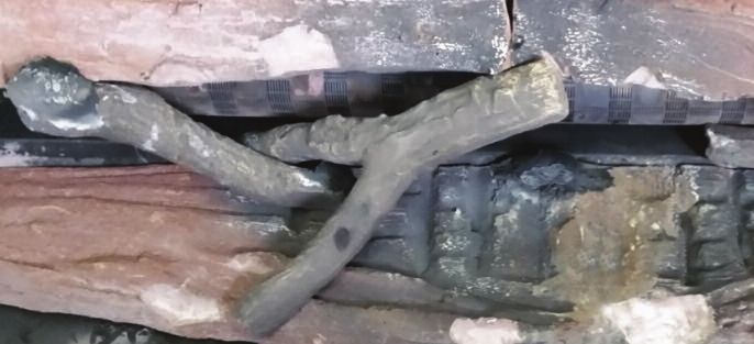
INSTALLATION INSTRUCTIONS (continued)
         FLUE TERMINATION LOCATION
         •   Flue terminations shall not be recessed in walls or sidings.
         •   EXTREMELY IMPORTANT: In heavy snow areas take extra care to prevent blocking
             flue termination with snow removal equipment.
         •   Flue gases exiting flue terminals are very hot and must not be restricted to assure fireplace
             combustion is not affected.
         •   Do not place, build any obstruction, plant any bushes or for any reason attempt to conceal
             the flue termination. To do so will affect the operation of the fireplace and may be hazardous.
         •   This unit must always vent directly to outdoors.

         GAS CONNECTION – 15mm (1/2”) Compression union
         ELECTRICAL CONNECTION – 3 Pin 10 Amp GPO plug
         POWER RATING OF APPLIANCE – 230V 50Hz 0.55Amp

                                                                                                             7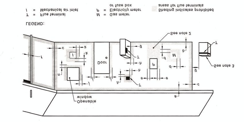
ACCENT 800 FLUE TERMINATION (COWLS)

8
INSTALLATION INSTRUCTIONS (continued)
         SETUP WITH EXTERNAL WALL MOUNTED FAN TERMINAL

         Wall mounted fan terminal

                                     1/ Wall mounted fan module – terminal must be
                                     installed with clearances as specified by AS/NZS
                                     5601.1 Clause 6.9.3
                                     2/ Run exhaust flue and air intake flue as required
                                     – Maximum run 5m. Flues can be run next to each
                                     other. Maintain the required clearances to
                                     combustibles.

                                            3/ Connection to appliance
                                            Cut tube to length where required.
                                            Ensure ends are burr free and round, test fit flue
                                            will slide over connection.

                                                                                                 9
INSTALLATION INSTRUCTIONS (continued)

         Recommended Silicon – Non-acetic, neutral cure 150degc or higher temperature rated.
         Bostik RTV 926 or similar.
         Apply an 8mm thick silicon bead fully around heater connection approx. 10mm from the top.
         Apply an 8mm thick silicon bead fully around the lower fan connection spigot approx. 10mm from
         the end.

                                                    Apply an 8mm silicon bead fully around
                                                    the inside of the flue end (heater
                                                    connection end)
                                                    Fit flue clamp over flue (loosely).

                                                    Slide flue onto connection spigot fully.
                                                    Tighten clamp fully.
                                                    Wipe excess silicon, visually check connection to
                                                    ensure connection is fully sealed.

                                                    4/ Repeat above with air intake flue pipe to heater
                                                    connection.
                                                    5/ Clip flues as required to provide adequate support.
                                                    6/ Connection to wall mounted fan terminal
                                                    Predrill mounting holes into wall.

10
INSTALLATION INSTRUCTIONS (continued)
Remove cover from fan terminal
Cut flue exhaust tube (hot tube) to length
(Approximately flush with wall exit). Wall
termination will sit against wall.
Pull flue tube through approx 100mm further
(will be pushed back once terminal fitted).
Cut Air intake flue 40mm longer.
Feed power cable through wall and into wall
terminal.
11INSTALLATION INSTRUCTIONS (continued)
Ensure ends are burr free and round, test
fit flue will slide over connection.
Apply an 8mm thick silicon bead fully
around flue connection plate spigot
approx. 10mm from the top.
Apply an 8mm silicon bead fully around
the inside of the flue end (heater
connection end)
Slide flue onto connection spigot fully.
Tighten clamp fully.
Wipe excess silicon, visually check
connection to ensure connection is fully
sealed.
Feed air intake flue pipe through location
spigot and fit retaining screw.
Push fan terminal into position. And affix to
wall.
Uneven or rough surfaces may require
sealant along top and side gaps.
Connect power cable connector.
Fit cable clamp to cable.
12INSTALLATION INSTRUCTIONS (continued)
Fit front cover
13TIMBER FRAME INSTALLATION
D*
2 x 84mm OD
FLUES
TRIM
A
Plaster to run
beyond stud and
behind trim
B
C
Frameout Dimensions (in mm)
A B C D*
620 840 450 1500
* Indication only. Can be smaller or larger.
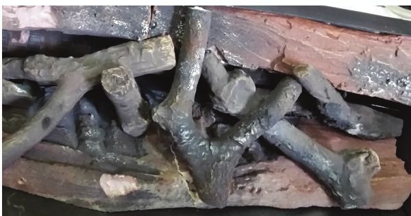
14MEDIA INSTALLATION
Media must be setup as per instructions
• The media is designed and shaped to correctly locate and remain in the correct position.
• DO not add extra media, or combine media types.
• Only the approved supplied media is to be used.
• Do not use any other media than as supplied and recommended by the manufacturer.
Use of other media may result in explosive media which may cause injury or damage.
Correct setup
• Insert rear log and push firmly back.
• Insert front long and bring fully forward
Insert log 1
Insert log 2
15MEDIA INSTALLATION (continued)
Insert log 3
Insert log 4
Insert log 5
16MEDIA INSTALLATION (continued)
Insert log 6
Insert log 7
17MEDIA INSTALLATION (continued)
Insert log 8
Insert log 9
Finished assembly
18COMMISSIONING PROCEDURE
Once the fire is installed.
• Install media.
• Connect to gas and power.
• Fit firebox door.
• Check for gas leaks.
• Connect powerflue module loom to fan control unit.
• Carry out the lighting procedure.
• Check burner pressures and inlet supply pressure (Valve is non adjustable).
• Check appliance for combustion (CO) leakage.
• Turn off
• Fit trim.
• Handover instructions to owner.
• Instruct owner on how to operate the fireplace safely.
• Instruct owner how to isolate the appliance in an emergency.
19OPERATION – USER INSTRUCTIONS
• Do not operate if you smell gas. Turn appliance off, extinguish any open flame.
Contact your installer or a licensed gasfitter.
• Do not use if any part of this appliance has been submerged in water. Contact your installer
or a qualified service technician.
• Solid fuels must not be burnt in the fire. Leaves, sticks, wood, paper food or material must be
kept away from the fire.
• Appliance operates with luminous flames, carbon deposits may occur during operation.
Should the appliance fail to ignite or was recently turned off, allow 2 minutes before attempting to
reignite appliance.
In the event of abnormal operation please contact your licensed gas installer, gas service
personnel or Real Flame Pty Ltd. Abnormal operation may consist of the following, noisy fan,
excessive or small flame, unusual flame appearance or colour, excessive sooting or other.
REMOTE CONTROL OPERATION
Note
• not all remote control functions are available.
• In the event of loss of power, the appliance will shut down safely. The appliance may
automatically resume operation once power is restored, pending the operation mode of the
remote control.
Transmitter LCD display
Remote Control
TECHNICAL DATA
Supply Voltage 4.5V (three 1.5 V AAA batteries)
Ambient temperature settings 0 - 50°C
Radio frequency 315 MHz
WARNING:
THE TRANSMITTER AND RECEIVER ARE RADIO FREQUENCY DEVICES.
20
PLACING THE RECEIVER IN OR NEAR METAL MAY SEVERELY REDUCE THE
SIGNAL RANGE.OPERATION – USER INSTRUCTIONS (continued)
ATTENTION:
• TURN OFF THE MAIN GAS SUPPLY OF THE APPLIANCE DURING INSTALLATION OR
MAINTENANCE OF THE RECEIVER DEVICE.
• TURN OFF MAIN GAS SUPPLY TO THE APPLIANCE PRIOR TO REMOVING OR
REINSERTING THE BATTERIES.
• IN CASE OF REMOTE CONTROL MALFUNCTION TURN OFF THE IFC DEVICE USING
THE ON/OFF SWITCH.
• FOR INSTALLATION/MAINTENANCE SWITCH OFF THE IFC DEVICE REMOVING MAIN
POWER SUPPLY PLUG.
OPERATING PROCEDURE
Initialising the system for the first time
Power the receiver. Activate the procedure of the receiver address programming, see the receiver
instruction (*). The receiver will “beep” three (3) times to indicate that it is ready to synchronize with
a transmitter. Install the 3 AAA type batteries in the transmitter battery bay, located on the base of
the transmitter. With the batteries already installed in the transmitter, push the On button. The
receiver will “beep” four times to indicate the transmitter’s command is accepted and sets to the
particular code of that transmitter. The system is now initialised.
(*) The receiver may be independent or integral to the IFC hearth appliance control module.
The receiver instruction may not be independent when part of the IFC.
Battery compartment
Temperature indication display
With the system in the OFF position, press the thermostat key and the mode key at the same time.
Look at the LCD screen on the transmitter to verify that a C or F is visible to the right of the room
temperature display.
Remote control display Remote control display
in Farenheit in Celcius
Turn on the appliance
With the system OFF, press the ON/OFF key on the transmitter. The transmitter display will show
some other active icons on the screen. At the same time the receiver will activate the appliance. A
single “beep” from the receiver will confirm reception of the command.
21OPERATION – USER INSTRUCTIONS (continued)
Turn off the appliance
With the system ON, press the ON/OFF key on the
transmitter. The transmitter LCD display will only
show the room temperature. At the same time the
receiver will turn off the appliance. A single “beep”
from the receiver confirms reception of the command.
Remote control display
Remote flame control
The proflame has six (6) flame levels. With the system ON, and the flame level at the maximum in
the appliance, pressing the down arrow key once will reduce the flame height by one step until the
flame is turned off.
The up arrow key will increase the flame height each time it is pressed. If the up arrow key is
pressed while the system is on but the flame is off, the flame will come on in the high position. A
single “beep” will confirm reception of the command.
Flame off Flame Level 1 Flame Level 5 Flame Level Maximum
Room thermostat (Transmitter Operation)
The remote control can operate as a room thermostat. The thermostat can be set to a desired
temperature to control the comfort level in a room.
To activate this function, press the thermostat key. The LCD display on the transmitter will change
to show that the room thermostat is “ON” and the set temperature is now displayed. To adjust the
set temperature, press the up or down arrow keys until the desired set temperature is displayed on
the LCD screen of the transmitter.
ROOM
TEMPERATURE
SET TEMPERATURE
22OPERATION – USER INSTRUCTIONS (continued)
Smart thermostat (Transmitter Operation)
The smart thermostat function adjusts the flame height in accordance with the difference between
the set point temperature and the actual room temperatures. As the room temperature gets closer
to the set point the smart function will modulate the flame down. To activate this function, press the
thermostat key until the word “SMART” appears to the right of the temperature bulb graphic.
To adjust the set temperature, press the up or down arrow keys until the desired set temperature is
displayed on the LCD screen of the transmitter.
Note: When the smart thermostat is activated, manual flame height adjustment is disabled.
Smart flame function
Fan speed control - this function is not supported on this fire.
Remote dimmer control (Light) - this function is not supported on this fire.
Split flow control - this function is not supported on this fire.
Continuous pilot/intermittenet pilot (CPI/IPI) selection
With the system in “OFF” position, press the mode key to index to the CPI mode icon.
Pressing the Up arrow key will activate the Continuous Pilot Ignition mode (CPI). Pressing the
Down arrow key will return to IPI. A single “beep” will confirm reception of the command.
NOTE: This fire is designed to run in IPI mode (Intermittent Pilot). The fire is factory preset to
operate in this mode.
Should the fire or remote need factory resetting, the IPI mode must be reselected. Should the
remote be in CPI mode or the pilot remains constantly on, please contact Glen Dimplex or your
installer to correct the settings.
23OPERATION – USER INSTRUCTIONS (continued)
Key Lock
This function will lock the keys to avoid unsupervised operation. To activate this function press the
Mode and Up keys at the same time. To de-activate this function, press the Mode and Up keys at the
same time.
Low battery power detection - transmitter
The life span of the remote control batteries depends on various factors: quality of the batteries
used, the number of ignitions of the appliance, the number of changes to the room thermostat set
point, etc.
When the transmitter batteries are low, a battery icon will appear on the LCD display of the
transmitter before all battery power is lost. When the batteries are replaced this icon will disappear.
Remote auxilliary relay control - this function is not supported on this fire.
Changes to the remote settings will not effect or change the appliance operation.
AUX
24TROUBLESHOOTING
Problem Possible Cause Remedy
When remote is Remote not talking to receiver • Listen for beep for signal being received
activated nothing • Check power to appliance is on
happens
• Check batteries in remote
• Reprogram remote to reciever
Fire cuts off and will Over temperature safety has • Allow fire to cool and reattempt ignition.
not relight tripped • Check room fan is not blocked.
• Check fire airflow is not restricted
Flame appears low or Incorrect gas or pressure • Check test point pressure and supply pressure to
excessively high appliance.
• Check gas type
• Replace valve if required
• Check injector for blockage and size
Smell in room while Paint curing or firebox door leak • If new appliance - run for several hours, open all
operating room ventilation and allow paint to cure.
• Turn off appliance and the have door seal
inspected by service personnel or Real Flame
agent.
Room air fan is noisy Faulty or dirty fan • Fan to be inspected and cleaned
or not working • Replace fan
Appliance operates Remote IPI/CPI incorrectly set • Correct remote control mode to IPI setting.
correctly but pilot
remains constantly
on.
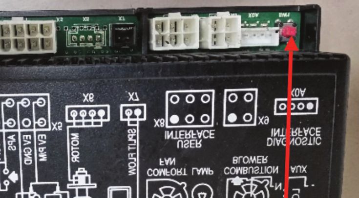
25REMOTE CONTROL (must be performed by an authorized service technician)
TEACHING RF CODE – Reprogramming remote to heater
1. Electrical tray must be slid forward to reprogram a remote control.
2. Turn the remote to off mode
3. Turn mains power to heater on.
4. Press the red button on the receiver once – three beeps should be heard.
Button location
5. Press the on button on the remote – four beeps should be heard.
6. Remote is now connected.
FAULT CODES
Gas Valve controller – no
fault codes available.
Remote – no faults codes
available.
If your fireplace still does not operate correctly consult your dealer,
installer or gas service technician.
All service and repairs should be performed by an authorised agency
All spare parts are available from Real Flame Pty Ltd.
26WIRING DIAGRAM
27CONVERSION DETAILS
Natural gas / ULPG.
1. Electrical tray must be slid forward to reprogram a remote control.
Valve, pilot injector and main burner injector must be changed to suit gas type.
2. Turn the remote to off mode
3. Turn mains power to heater on.
4. Press the red button on the receiver once – three beeps should be heard.
1. Turn appliance off.
VALVE CHANGE
2. Turn gas supply off.
3. Remove trim.
4. Disconnect gas pipe from isolation valve to burner.
5. Remove retaining nuts from electrical tray and slide tray forward.
6. Disconnect gas pipe from valve outlet.
7. Disconnect valve wires from ignition pack.
8. Remove valve from electrical tray (3 retaining screws)
9. Remove gas pipe connections from valve and fit to correct gas type valve.
10. Reattach valve to mounting plate.
11. Reconnect valve wires from ignition pack.
12. Reconnect gas pipe to the valve outlet and the inlet pipe.
13. Slide electrical tray into position and attach / tighten retaining nuts.
14. Connect gas pipe to isolation valve.
15. Ensure all connections are tight.
16. Connect gas and leak test connections upto the gas valve.
17. Remove firebox door (6 screws)
PILOT AND INJECTOR CHANGE
18. Remove twig media from firebox.
19. Remove front log media.
20. Remove front media support (2 screws accesed from electrical area)
21. Lift out front media support
22. Loosen retaining nut from end of burner and lift burner out.
23. Remove injector and replace with correct gas type injector, ensure injector is tightened into holder.
24. Replace burner and refit holding nut at end.
25. Unclip pilot head and lift off.
26. Undo pilot spud using allen key from above
27. Refit correct pilot spud, fully tighten
28. Refit fit pilot head and clip into place
29. Refit front media support
30. Refit front log
31. Refit media as per media setup (refer previous section in instructions)
32. Refit firebox door.
33. Fit manometer to TPP.
34. Start appliance and check for gas leaks.
35. Start appliance and check burner pressure.
36. Check appliance for correct flame operation
37. Remove manometer and tighten gas test point.
38. Check for gas leaks.
39. Check door and appliance for spillage or CO leakage.
40. Turn appliance off.
28 41. Refit front trim.PARTS LIST
1 Valve
2 SIT Pilot assembly
3 Injector
4 Burner
5 Remote control
6 Sit Ignition pack / gas control
1 2 3
4
5 6
2930
31
GLEN DIMPLEX AUSTRALIA PTY LTD
            ABN 69 118 275 460

    Head Office/Factory/Showroom
          1340 Ferntree Gully Rd.
            Scoresby Vic 3179
 Ph: (03) 8706 2000 Fax: (03) 8706 2001
      E-mail: info@realflame.com.au
       Richmond - VIC Showroom
               300 Swan St.
            Richmond Vic 3121
 Ph: (03) 9428 4443 Fax: (03) 9428 4445
      Dandenong - VIC Showroom
    3/328 South Gippsland Highway,
        Dandenong South Vic 3164
            Ph: (03) 9702 7853
E-mail: sales@realflamedandenong.com.au
        Geelong - VIC Showroom
           1/2A Gordon Avenue.
          Geelong West Vic 3218
             Ph/Fax: 5229 0844
E-mail: realflamegeelong@hotmail.com.au
        Sydney - NSW Showroom
           546 Pacific Highway.
          Chatswood NSW 2067
 Ph: (02) 8905 0189 Fax: (02) 8905 0192
      E-mail: info@realflame.com.au
       Miranda - NSW Showroom
               36 Kareena Rd
             Miranda NSW 2228
 Ph: (02) 8513 6202 Fax: (02) 9520 1974
 E-mail: fireplace@realflamesouth.com.au
        Adelaide - SA Showroom
            173 -175 Magill Rd.
             Norwood SA 5067
 Ph: (08) 8132 0371 Fax: (08) 8132 1687
  E-mail: realflamesa@iprimus.com.au
        Milton - QLD Showroom
             46 Douglas St,
            Milton QLD 4064
           Ph: (07) 3368 2011
          Perth – WA Showroom
         47-53 McDonald St East,
          Osborne Park WA 6017
 Ph: (08) 9444 9900 Fax: (08) 9444 9800
      Fyshwick – ACT Showroom
           88 Wollongong St,
          Fyshwick ACT 2609
          Ph: (02) 6280 5522
     Ulverstone – TAS Showroom
            31A Victoria St,
         Ulverstone TAS 7315
          Ph: (03) 6425 4440
You can also read