Circuitry solution for smart watches using a stationary power supply
←
→
Page content transcription
If your browser does not render page correctly, please read the page content below
E3S Web of Conferences 273, 04005 (2021)                                     https://doi.org/10.1051/e3sconf/202127304005
INTERAGROMASH 2021

         Circuitry solution for smart watches using a
         stationary power supply
         Aleksey Grishin1,* and Alexandr Alibutaev2
         1
             Saint Petersburg State Agrarian University, Petersburg Highway 2, 196601 Saint Petersburg, Russia
         2
             National Research University ITMO, Kronverkskiy prospect, 49, 197101 St. Petersburg, Russia

                        Abstract. Overwork and mistakes in organizational management are the
                        main reasons why people experience stress and fatigue in the workplace.
                        These problems entail reduced employee productivity and additional costs
                        for organizations. It is difficult for a person to recognize mental overwork
                        or burnout in the early stages, primarily because of the subjectivity of his
                        feelings. One way to diagnose mental health problems is to analyze
                        physiological indicators such as temperature, pulse, and electrical activity of
                        the skin. It is possible to track these indicators using a wearable watch.
                        However, a large number of sensors may not fit into the watch form factor.
                        The aim of the work is to create a smart watch circuit with a power supply
                        and sensors wired on the board. The designed solution, due to the versatility
                        of the topological equipment of the boards is the least energy-consuming,
                        since the components of the power supply and the control circuits make up
                        an open-frame design. This allowed them to be located in the most favorable
                        position and to use galvanic isolation in the primary and secondary power
                        supply circuits without affecting the auxiliary control circuit of the sensors.

         1 Introduction
             Every day a person faces problems that endanger his health, the most common are listed
         below:
         x Mental problems: depression, emotional burnout, prolonged stress due to a violation of
             resources in one of the areas of life [1];
         x Physiological problems: trauma, poisoning, illness, accidents;
             As a rule, some problems arise from others: with mental fatigue, attention and
         concentration decrease, and, as a result, work-related injuries may occur [2]. The opposite is
         also true - for example, among people infected with coronavirus infection, 70% said they feel
         stressed, and a quarter indicated symptoms of depression [3].
             If many physiological problems can be prevented at the initial stage due to painful
         sensations that signal malfunctions of the body, then mental problems can go unnoticed and
         ignored for a long time. For example, the emotional burnout syndrome inherent in social
         workers begins to form at the stage when a person is inspired and feels an emotional uplift
         due to new prospects that have opened up. Because of this, a person overworks and disturbs
         his balance of vital resources: the physical and social requirements of the environment are

         *
             Correcting author: grischin.aleks201086@gmail.com

   © The Authors, published by EDP Sciences. This is an open access article distributed under the terms of the Creative
   Commons Attribution License 4.0 (http://creativecommons.org/licenses/by/4.0/).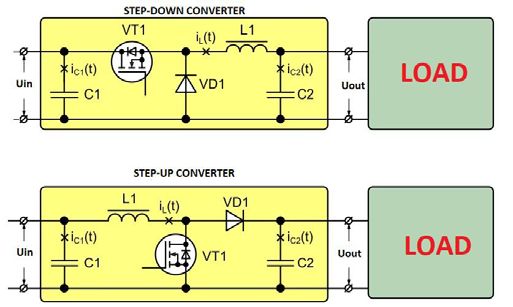
E3S Web of Conferences 273, 04005 (2021)                               https://doi.org/10.1051/e3sconf/202127304005
INTERAGROMASH 2021

         not met, due to the prevalence of labor requirements. This provokes the emergence of a
         stressor, such as a subjective assessment of reality, which leads to stress response and burnout
         syndrome in its initial stage. To prevent its further development, it is necessary to allocate
         resources to other areas of life. However, this often does not happen: it is difficult for a person
         to distinguish the emerging mental stress from the desire to procrastinate. This becomes the
         reason for the appearance of subsequent symptoms: decreased interest, decreased
         performance and motivation, reduced creativity, dulling of emotions and, ultimately,
         depression [4].
             Delaying a session with a therapist and ignoring symptoms early on can incur economic
         costs. They will be carried not only by the person, but also by his employer. Companies lose
         more than $ 7600 annually to mental health problems for a single employee [5]. As a rule, in
         69% of cases, mistakes in the management of the company become a catalyst for burnout,
         including unclear setting of tasks, unclear distribution of responsibility and inconsistency of
         actions. Often, all these reasons are difficult to identify at the start. As a rule, they appear
         already during prolonged work on a project or a specific task. From this it becomes clear that
         taking care of the mental health of an employee is a constant process and responsibility for it
         lies both with the person and the employer.
             As mentioned above, mental disorders are often physiological. It has been established that
         sweating, pulse and body temperature are a response to mental stress experienced by a person
         [6]. Thus, it becomes possible to identify long-term stress and alert the person in advance.
             Modern wristbands, fitness trackers and smartwatches allow you to track your heart rate
         and many other factors for monitoring the body's work. However, due to the complexity of
         the technical solutions, they are still difficult to use to measure stress. A watch of this format
         will not fit its form factor. The article proposes to consider a possible technical solution for
         tracing the control board and changing the power supply system of the control circuit,
         developed empirically and tested on a prototype model.
             The device "Medical watch" is a universal device for monitoring and processing data of
         the user's health. In the modern world, many leading companies specializing in the production
         of gadgets produce their own smartwatches, but each of them focuses on its own direction in
         production, and only a few companies are engaged in the production of specialized medical
         watches.

         2 Materials and Methods
         In the next part of our article, we will consider the possibility of creating a universal medical
         watch with possible technical solutions.
             To begin with, we will determine what is the essential difference between these watches
         and manufactured and well-known brands. The most important thing is their specialization.
         The main functions of the watch are three areas: collection, processing and storage of
         information.
             Gathering information is one of the most difficult watch functions to implement. For the
         accuracy and quality of information collection, it is necessary to obtain accurate and high-
         quality data. The checking mathematical model should process them, taking into account the
         measurement error. Consider the most pressing problem for the modern world, due to the
         long periods of self-isolation. In 2020, many people began to develop depression or a pre-
         repressive condition, which can also be dangerous both for a person's health and for the work
         performed by him. In order to diagnose depression in a person, it is necessary to use sensors
         that measure the pulse, temperature, and the potential difference of a person's resistance
         measured in a small area, but from different sides of the hand: the back and front sides. For
         this, the following set will be used: a skin electrical activity sensor, touch sensors (can be

                                                         2
E3S Web of Conferences 273, 04005 (2021) https://doi.org/10.1051/e3sconf/202127304005
INTERAGROMASH 2021
replaced with a moisture sensor), IR sensors (temperature sensor). To obtain more accurate
information with less error, the sensors must be positioned as shown in Figure 1.
Fig. 1. An example of the location of sensors on a medical watch for diagnosing psychological fatigue
As seen in Figure 1, the Electrodermal Activity Sensor (EDAS) (number 1) must be
positioned in the center of the watch back. This is to ensure that excess moisture does not
interfere with the sensor measurements and does not cause false readings. EDAS is used to
monitor the performance of human electrical impulses passing through the human body. With
a high level of experience, anxious or aggressive state of a person, a rapid and dense
movement of electrical particles in the body occurs. This indicator in a stable state is in the
range of 0-0.18% (relative excess of the average), in aggressive states - 0.26-0.34%, and in
an anxious or when a person is subjected to a panic attack - 0.67-0.84%. It is also necessary
to take into account that under some conditions the human body automatically begins to
produce additional particles or accelerate their movement, for example, with physical
activity. Therefore, in these indicators it is necessary to add an error in the form of 0.05-
0.08% [7].
The use of a heart rate sensor is necessary to measure the pulse. For the average adult, the
norm is 60 beats per minute, when a person experiences fear or anxiety, the number of beats
is 80-120 beats. Exactly the same amount and with vigorous physical activity. To separate
them from stress, you need to take into account data from several sensors, including the use
of GPS. It is also allowed to replace it with a humidity sensor, and then the measurements
take place according to the person's perspiration. The location of the sensor is indicated by
number 2. As you can see from the figure, it is located in almost the same way as the EDAS.
This is due to the peculiarities of its operation and the principle of supplying power to them
and the methods of the topology of the control board, which will be considered below.
And before proceeding to the consideration of technical solutions in the development of
these watches, let's consider the last sensor - the IR sensor. For correct and more accurate
operation of the watch, three IR sensors are used, indicated in Figure 1 by the numbers 3,4,5,
but to determine the stress, only the sensor indicated by the number 4 is needed. As you can
see from the figure, it is located on the inside of the watch, next to the bracelet attachment
point. This is necessary in order to track the temperature indicators of a person. Next
requirements are imposed on the mounting and positioning of the sensor: it should not fit
tightly to the human skin, but the clearance distance should also be small. This is necessary
to reduce the measurement error. It should be borne in mind that the average statistical spread
of temperature values is ± 0.2° С, and with experience, stress or aggression, this indicator
changes within ± 0.4° С [7-8].
3 Results
Having studied and understood the basic properties of the watch, you can proceed to the
technical solution that was used in this watch, the main emphasis when considering these
solutions will be placed on the power source (power circuit), which is not presented in a
3E3S Web of Conferences 273, 04005 (2021) https://doi.org/10.1051/e3sconf/202127304005
INTERAGROMASH 2021
standard form, as in modern modern smart watches. The main distinguishing feature is that
the entire power supply (PS) circuit is located on a printed circuit board, in close proximity
to the control circuit, which primarily leads to a reduction in information transmission
interference and a reduction in power dissipation. A comparative analysis of the circuit is
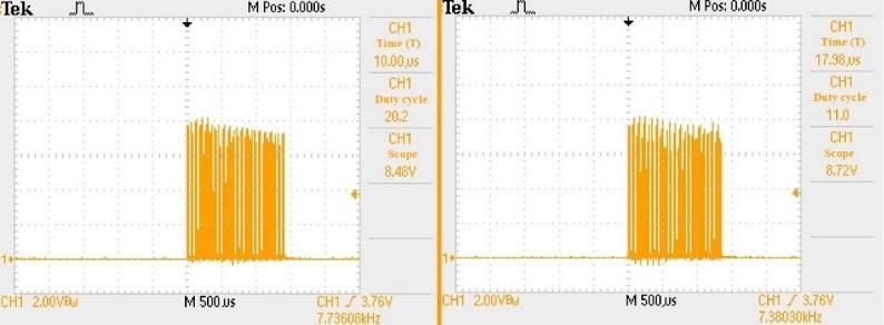
presented in Table 1. Figure 2 shows a comparison of the control circuit (CC) enable signals
when using power methods such as stand-alone versus onboard PS.
Table 1. Analysis of the use of a topology with an on-board power supply.
Stand-alone (modular)
Criterion name onboard converter
converter
Input voltage range, V 10.5-36 17-34
Peak current consumption, mA 280 295
Power consumption range, W 3.9 4.8
Dissipated power,% 2-4 3.4-4.9
Fig. 2. Oscillograms of switching on the control circuit using the built-in and modular power supply
When examining oscillograms, two conclusions can be drawn:
1. With built-in power supplies, the control circuit has a lower delay time, as shown in the
left figure. This means faster response of the microcontroller, which consequently leads
to less power consumption and minimized power dissipation. The less power dissipated,
the more stable the clock will run by minimizing the outgoing noise interference. Also,
there is minimal heating of the case, which does not cause discomfort when worn and
provides a long battery life.
2. With a modular design (oscillogram on the left) of the PS installation, it can be seen that
the emission of signals occurs more, and the width of the pulse packets takes longer,
which is a consequence of a longer switching on of the microcircuit. If the control circuit
is switched on for a long time, there is a possibility of noise interference and violation of
electromagnetic compatibility (EMC). This leads to the need to use noise suppression
filters in the device, and thereby increases its dimensions and makes the device more
expensive and less maintainable.
When choosing a layout (routing) of the board, it is necessary to determine the power
supply circuit used, hereinafter referred to as the dc / dc converter. There are two schemes
implemented on these sources, this is a step-up and a step-down, the peculiarities of which
are shown in Figure 3.
4E3S Web of Conferences 273, 04005 (2021) https://doi.org/10.1051/e3sconf/202127304005
INTERAGROMASH 2021
Fig. 3. Basic circuits used in the development of a dc/dc converter
The downward dc / dc converter has its own specific structure of work, which must be
taken into account when using its circuit in conjunction with other devices. This is the
presence of parasitic capacities, thanks to which it works. As can be seen from Figure 3, the
downconverter presented on it has such components as: transistor VT1, capacitor C1 and
inductance L1 (the diagram does not show the same parasitic capacitances that were
mentioned earlier). In the form of the load itself for the converter, the DA1 control circuit is
used. A positive voltage comes to the control circuit and the microcontroller starts up, thereby
bringing the rest of the work circuits into operation. In order to ensure stable operation of the
parasitic capacitances, two capacitors are installed in front of the control circuit, which will
smooth out the pulse signals from the converter. That is, they will be signal filters. With the
help of the capacitance of these capacitors, you can directly set the level of the signal that
goes to the control circuit [8].
Now let's move on to the proposed solutions to the problems that were formulated earlier:
stable signal supply to the control circuit with parameter optimization and reduction of
electromagnetic compatibility interference.
In smart watches, it is proposed to use three printed circuit boards (PCBs), which are
multilayer. These boards will be connected not with industry-standard “male-female”
contacts, but with pin tabs. This will provide such requirements as reliability in case of shocks
or falls, and fast signal (voltage) transmission, by reducing unnecessary contacts and possible
malfunctions [9, 10]. For stable operation, we place on the first board only those parts of the
components that are in the primary circuit. These are the filters of the input signals and the
connection of all pins to which the power must be suitable. It is also necessary to calculate
the parasitic capacitances contained in each component. A transformer must be installed on
the second board. In this case, both a planar transformer and an inductor can be used.
However, with an inductor, the overall parameters increase, and with a planar transformer,
the price of a watch will rise. On the second (middle) board, it is also possible to arrange
primary information sensors and sensors whose error probability is no more than ± 2%. This
will allow evenly and balanced supply of stable power on the third board to the control circuit.
The control circuit and all control components of the converter, as well as precision sensors
and current setting resistors are connected to the third board. It should be located just below
the display and be 8 mm wider than the second board. This will allow you to connect it to the
first board without unnecessary jumpers. When developing the topology of the third board,
it is necessary to take into account that all vias should be no more than 0.6 mm, and the length
of the tracks should not be more than 2 mm, their width should not be less than 0.4 mm.
These requirements, as studies show, allow the transmission of signal and voltage with losses
that make up less than 1% of the total volume. The voltage already converted in the
transformer comes to the board, and it should immediately fall on the Snubber circuit, thereby
5E3S Web of Conferences 273, 04005 (2021) https://doi.org/10.1051/e3sconf/202127304005
INTERAGROMASH 2021
ensuring a stable voltage level and a given level of current required for consumption by the
converter microcircuit [11, 12].
A series of studies shows that for small (low-power, not exceeding 6 W in power)
converters, it is better to use analog microcircuits, which in turn will provide stable operation
and built-in overvoltage or short circuit protection.
From the converter control microcircuit, signal tracks are sent to the input filter capacitors
of the control circuit to smooth the signal. We also send them to the transistors that are
necessary for the sensors to work (transistors must be calculated in a range twice the peak
voltage value). Further, we send the signal from the transistors to the control terminals of the
sensors, thereby ensuring their stable operation. It is also necessary to organize the
synchronous operation of transistors (open-close mode), which can be done by calculating
the current setting resistors of the sensor circuit [13].
4 Discussion
The main distinguishing feature is the use of the technology of positioning the converter by
the smallest distance to the control circuit. It is proposed to place it not in a modular design,
as is usually used in similar devices, but directly on the board itself. This will lead to
significant cost savings and make the device more maintainable. However, for such an
implementation, it is necessary to use only a step-down circuit, since it contains the smallest
number of components, which means it is easier to use and configure [14].
For the solution of the second question related to the electromagnetic compatibility of
watches, it is worth noting two important factors. The first is the conversion frequency
(operating frequency). If the clock used a frequency not exceeding 150 kHz, then the
interference would not be significant. However, since compactness is required in the overall
dimensions of the finished product, the calculated conversion frequency will be 290-310 kHz,
which must already be controlled [15]. This can be done using an output noise filter due to a
line of smoothing filters installed in the circuit immediately after the output of the
microcircuit, which sends a signal to the load (control circuit).
Further, it is necessary to determine the conversion factor in the transformer. The
optimum is - 3, since this parameter will allow you to use a wider input voltage range and
stable conversion at the output. This, in turn, gives a wide range of parameters for the choice
of the core and the calculation methodology, development of the transformer.
The proposed topological solution introduces an innovation to the existing circuit by
introducing current-sensing resistors into the control circuit to control the pulse currents fed
to the Vcc pin of the control circuit. As a result, this stabilizes the input signal level in a
narrow range, which allows processing signals from sensors without interference and noise,
as a result, to obtain a minimum level of error, which guarantees obtaining accurate data
when processing and analyzing information. The main result can be considered a decrease in
power dissipation to 0.8-1.0 W. The nominal operating time of the clock with this type of
topology is at least 150 hours. The total power consumption is reduced from 12 W to 8 W,
reducing the heating of the case by 3 ° C.
5 Conclusions
Thus, the designed model of the watch has the sensors needed to track the mental state in real
time. The proposed solution will allow companies to compensate expenses of an employee's
social package, reduce the number of work-related injuries and accidents. Timely detection
of stress will allow identifying problems in the management of the organization and
6E3S Web of Conferences 273, 04005 (2021) https://doi.org/10.1051/e3sconf/202127304005
INTERAGROMASH 2021
responding to them in a timely manner. This will help employee to save productivity at the
same level.
Use of the proposed topology of the board in smart watches will increase their performance,
and will reduce repair costs, since replacement of components will no longer require a full
parsing of the clock, including diagnostic work. Described solution would increase the
efficiency up to 92%, with an average of 87-90%. With the distributed use of power supplies,
the overall parameters of the clock are reduced.
The watch developed according to the described project will be highly competitive due
to its compactness and measurement accuracy. This will help compete with major
manufacturers such as Huawei, Samsung, Apple and Xiaomi. Thanks to such competition, it
will be possible to import substitution of smart watches, which will provide domestic
manufacturers with high profits, as well as the possibility of additional earnings - by opening
specialized service centers and additional maintenance and support for the development of
smart watch software.
References
1. C. Maslach, M. Leiter, World Psychiatry 15, 103-111 (2016) doi:10.1002/wps.20311
2. P. Atroszko, Z. Demetrovics, M. D. Griffiths, Int J Environ Res Public Health 17 (2020)
doi:10.3390/ijerph17020660
3. F. Tang, J. Liang, H. Zhang, M. Hamid, M. Kelifa, Q. He, P. Wang, Psychology and
Health 36, 164-178 (2020) doi:10.1080/08870446.2020.1782410
4. M. Burisch, Das Burnout-Syndrom (2014) doi:10.1007/978-3-642-36255-2
5. S. Han, T. Shanafelt, C. Sinsky, J. Goh, Ann Intern Med. 170, 784-790 (2019)
doi:10.7326/M18-14226
6. L. Díaz-Rodríguez, M. Arroyo-Morales, C. Fernández-de-las-Peñas, F. García-Lafuente,
C. García-Royo, I. Tomás-Rojas, B. Res Nurs. 13, 376-382 (2011)
doi:10.1177/1099800410389166
7. K. Chen, W. Fink, J. Roveda, R. D. Lane, J. Allen, J. Vanuk, In: IEEE 2015 12th
International Conference on Wearable and Implantable Body Sensor Network, 1-6
(2015) doi:10.1109/BSN.2015.7299369
8. M. Zubair, C. Yoon, H. Kim, J. Kim, J. Kim, Smart Wearable Band for Stress Detection,
In: 2015 5th International Conference on IT Convergence and Security (ICITCS). IEEE,
1-4 (2015) doi:10.1109/ICITCS.2015.7293017
9. M. Chaves, E. Margato, J.F. Silva, S.F. Pinto, J. Santana, IET Gener Transm Distrib 5,
368 (2011) doi:10.1049/iet-gtd.2010.0499
10. K. Shringarpure, S. Pan, J. Kim, J. L. Drewniak, IEEE Trans Electromagn Compat. 58,
849-858 (2016) doi:10.1109/TEMC.2016.2535459
11. J.-J. Yun, H.-J. Choe, Y.-H. Hwang, Y.-K. Park, B. Kang, IEEE Trans Ind Electron. 59,
1808-1814 (2012) doi:10.1109/TIE.2011.2141095
12. S.-W. Lee, H.-L. Do, IEEE Trans Ind Electron. 65, 7753-7761 (2018)
doi:10.1109/TIE.2018.2803731
13. R. Wu, J. H. Huijsing, K. A. A. Makinwa, IEEE J Solid-State Circuits. 46, 2794-2806
(2011) doi:10.1109/JSSC.2011.2162923
14. R. Luiz da Silva, T. B. Lazzarin, I. Barbi, IEEE Trans Ind Electron. 65, 8422-8432 (2018)
doi:10.1109/TIE.2018.2808900
7E3S Web of Conferences 273, 04005 (2021) https://doi.org/10.1051/e3sconf/202127304005
INTERAGROMASH 2021
15. S. K. Pandey, S. R. Mohanty, N. Kishor, Renew Sustain Energy Rev. 25, 318-334 (2013)
doi:10.1016/j.rser.2013.04.029
8You can also read