OPERATORS MANUAL LET'S BOUNCE - PLEASE NOTE
←
→
Page content transcription
If your browser does not render page correctly, please read the page content below
OPERATORS MANUAL
       LET’S BOUNCE

                  PLEASE NOTE
       Read this manual before operating the machine.
            Visit www.laigames.com for support.
1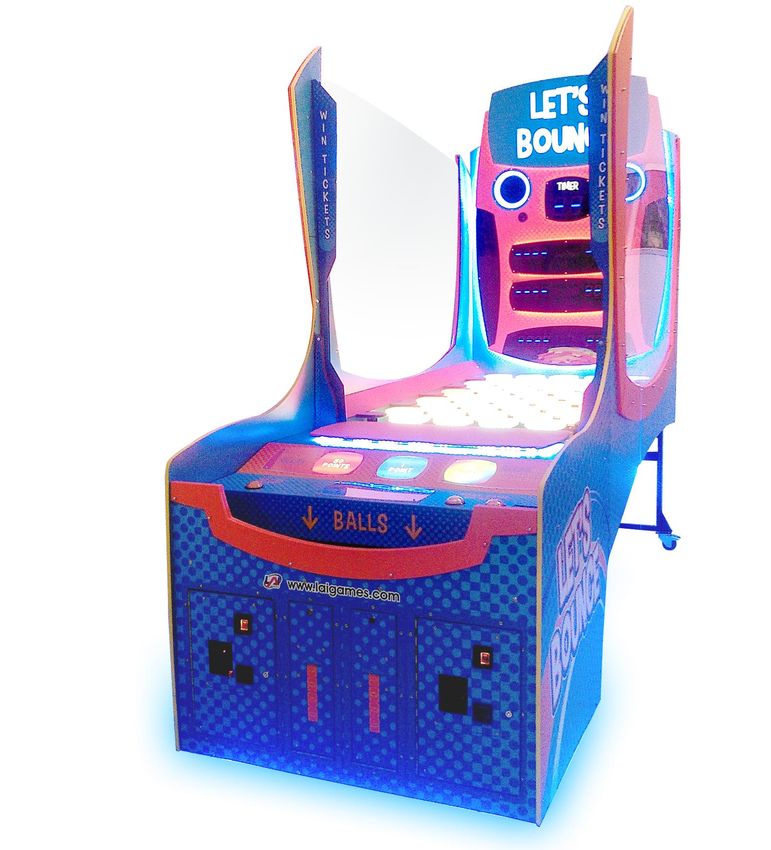
Correspondence regarding this machine should be addressed to
        your closest LAI Games office, or LAI Games Distributor.
       For contact details, refer to the back page of this manual.

    © LAI Games
    Copyright Notice:
    Authorization is hereby provided to you to copy this manual in its
    entirety provided such copies are used for non-commercial
    purposes and solely for use with LAI Games products. This
    authorization is specifically conditioned to include all legends,
    copyright, proprietary and other notices which appear herein are
    unaltered on any and all copies you make.

2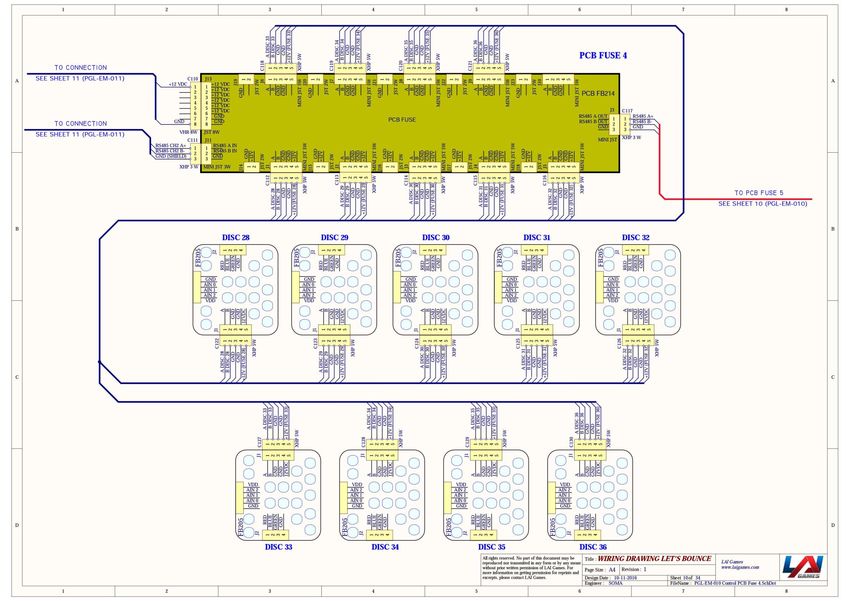
Table of Contents
SAFETY PRECAUTIONS............................................................................................................................. 6
MACHINE INSTALLATION AND INSPECTION ........................................................................................... 7
INTRODUCTION ....................................................................................................................................... 8
    DESCRIPTION....................................................................................................................................... 8
PACKAGING ............................................................................................................................................. 8
    CONTENTS ........................................................................................................................................... 8
    SPECIFICATIONS .................................................................................................................................. 8
       DIMENSIONS ................................................................................................................................... 8
       ELECTRIC SUPPLY............................................................................................................................. 8
    ASSEMBLY ........................................................................................................................................... 8
       CONTENTS DETAILED .................................................................................................................... 10
    GAMEPLAY AND MODES ................................................................................................................... 11
       OBJECTIVE ..................................................................................................................................... 11
       HOW TO PLAY ............................................................................................................................... 11
       ATTRACT MODE ............................................................................................................................ 12
       PLAY MODE ................................................................................................................................... 12
OPERATION ........................................................................................................................................... 13
    GAME SETTINGS ................................................................................................................................ 13
    AUDITS .............................................................................................................................................. 16
    INPUT AND OUTPUT TESTS ............................................................................................................... 17
       OUTPUT TESTS .............................................................................................................................. 17
       INPUT TESTS .................................................................................................................................. 17
       RUN TESTS ..................................................................................................................................... 17
    GAME HISTORY ................................................................................................................................. 18
    ERRORS.............................................................................................................................................. 18
SECTION A: SERVICE INSTRUCTIONS ..................................................................................................... 20
LOCATING AND ACCESSING PARTS ....................................................................................................... 20
       CABINET FRONT ............................................................................................................................ 20
       BACKBOARD .................................................................................................................................. 21
       PLAYER PANEL ............................................................................................................................... 22
       CABINET INNER ............................................................................................................................. 22
       CABINET REAR ............................................................................................................................... 23

3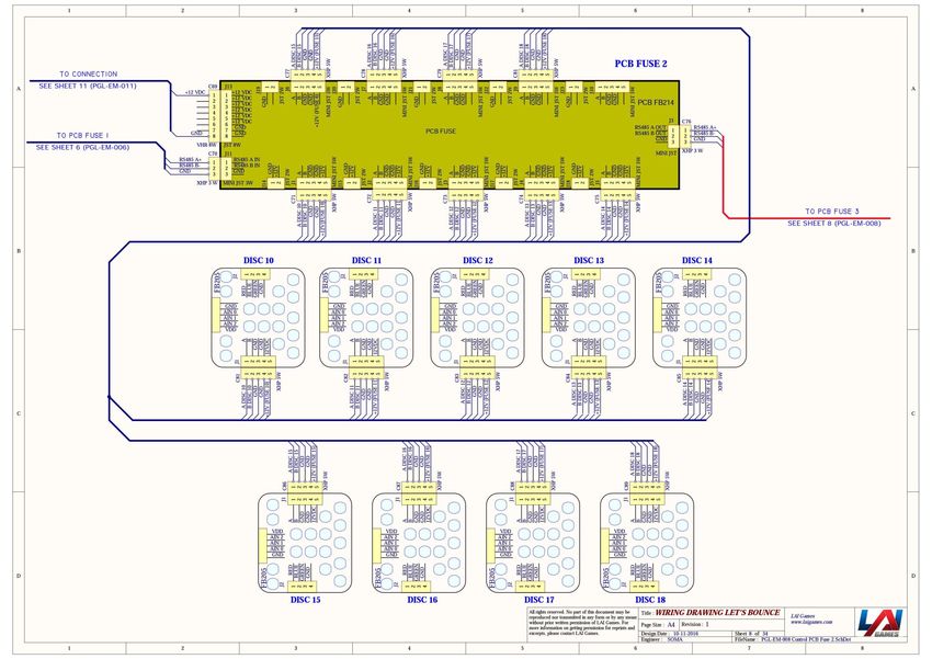
CABINET SIDE ................................................................................................................................ 24
       OPERATOR PANEL / SERVICE CONTROLS ...................................................................................... 24
    PARTS DESCRIPTION ......................................................................................................................... 25
       HEADER DISPLAY ........................................................................................................................... 25
       BACKBOARD .................................................................................................................................. 25
       SPEAKERS ...................................................................................................................................... 25
       PLAYFIELD...................................................................................................................................... 25
       COUNTERS ..................................................................................................................................... 26
       BUTTONS ....................................................................................................................................... 26
       VOLUME KNOB.............................................................................................................................. 26
       COIN MECHANISM / BILL ACCEPTOR / CARD SYSTEM .................................................................. 26
       TICKET MECHS ............................................................................................................................... 26
       PLAYFIELD FUSES – FB214 ............................................................................................................. 26
       GAME BOARD – FB216 .................................................................................................................. 27
       SOUND BOARD – FB106 ................................................................................................................ 27
       BALL DISPENSER ............................................................................................................................ 27
       POWER INLET/MAINS SWITCH...................................................................................................... 27
       POWER SUPPLY ............................................................................................................................. 27
    LAMPS ............................................................................................................................................... 27
    MAINTENANCE .................................................................................................................................. 28
       EXTERIOR....................................................................................................................................... 28
       INTERIOR ....................................................................................................................................... 28
SECTION B: TECHNICAL DETAILS ........................................................................................................... 29
    POWER SUPPLY ................................................................................................................................. 29
    COIN OPTIONS REFERENCE GUIDE.................................................................................................... 30
    UNIVERSAL CARD LINK CONNECTION ............................................................................................... 30
    TICKET MECHANISMS........................................................................................................................ 31
WIRING DIAGRAMS ............................................................................................................................... 32
MECHANICAL ILLUSTRATIONS .............................................................................................................. 52
    MAIN ASSEMBLY ............................................................................................................................... 52
    FRONT PANEL .................................................................................................................................... 53
    PANEL DOOR AND BASE FRONT PANEL ............................................................................................ 54
    COIN DOOR AND TICKET DOOR ........................................................................................................ 55
    COIN PLATE WITH DBA AND CASH BOX ............................................................................................ 56

4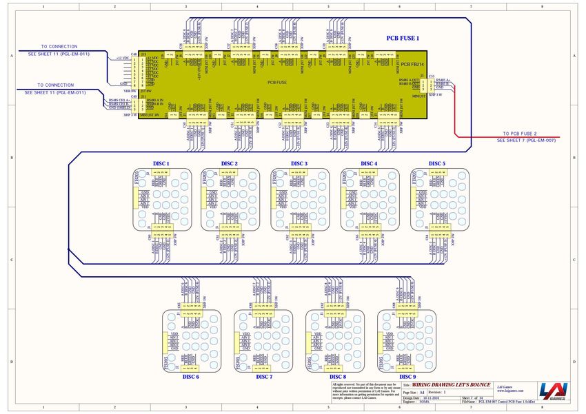
OPERATOR PANEL AND POWER SUPPLY........................................................................................... 57
    PLAYER PANEL ................................................................................................................................... 58
    RIGHT AND LEFT PLAYER PANEL STOPPER ........................................................................................ 59
    BALL GATE AND DB BOX ................................................................................................................... 60
    BALL GATE MOTOR AND DISPLAY SIGN ............................................................................................ 61
    BALL LIFTER AND BALL HOPPER CHUTE ............................................................................................ 62
    DISPLAY PANEL AND BASE DISPLAY PANEL ....................................................................................... 63
    BASE SCORE PANEL ........................................................................................................................... 64
    BOARD DISPLAY ROUND 1 AND BOARD DISPLAY ROUND 2 ............................................................. 65
    RIGHT AND LEFT SIDE WALLS ............................................................................................................ 66
    MAIN PLAYFIELD, BEAM FOUR TILES AND BEAM FIVE TILES ............................................................ 67

5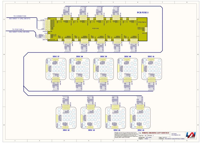
SAFETY PRECAUTIONS
The following safety precautions and advisories used throughout this manual are defined as follows.

    WARNING:               Disregarding this text could result in serious injury.

    CAUTION:         Disregarding this text could result in damage to the machine.

    NOTE:                         An advisory text to help understand.

                              PLEASE READ THE FOLLOWING

     WARNING:       Always turn OFF Mains AC power and unplug the game before opening or
                    replacing any parts.

                    Always grasp the plug, not the line cord, when unplugging the game from
                    an electrical outlet.

                    Always connect the Game Cabinet to a grounded electrical outlet with a
                    securely connected ground line.

                    Do Not install the Game Cabinet outdoors or in areas of high humidity,
                    direct water contact, dust, high heat or extreme cold.

                    Do Not install the Game Cabinet in areas that would present an obstacle in
                    case of an emergency, i.e. near fire equipment or emergency exits.

     CAUTION:      Always use a Digital Multimeter, logic tester or oscilloscope for testing
                   integrated circuit (IC) logic PC boards. The use of a continuity tester is not
                   permitted.

                   Do Not connect or disconnect any of the integrated circuit (IC) logic PC
                   boards while the power is ON.

                   Do Not use any fuse that does not meet the specified rating.

                   Do Not subject the game cabinet to extreme temperature variations.
                   Reliability of electrical components deteriorates rapidly over 60 oC.

6
MACHINE INSTALLATION AND INSPECTION
When installing and inspecting Let’s Bounce, be very careful of the following points and pay
attention to ensure that the players can enjoy the game safely.
Be sure to turn the power OFF before working on the machine.
WARNING: Always turn OFF mains power before removing safety covers and refit all safety
covers when work is completed.
Make sure the power cord is not exposed on the surface (floor, ground, etc.) where people walk.
Check that the rubber glide feet levellers are set correctly on the floor so that the game cabinet
is level and stable.
Always make complete connections for the integrated circuit (IC) logic PC Boards and other
connectors. Insufficient insertion can damage the electrical components.
Only qualified personnel should inspect or test the integrated circuit (IC) logic PC Boards.
If any integrated circuit (IC) logic PC Boards should need servicing, please contact the nearest LAI
Games Distributor (refer to the back page of this manual).
7
INTRODUCTION
Congratulations on your purchase of Let’s Bounce by LAI Games. We hope you take the time to read
this manual and learn about the many features and user-friendly adjustments that can be made to
fine-tune the game for maximum earning potential.
DESCRIPTION
Let’s Bounce is an addictive and rewarding single or multiplayer game that is easy to play but hard to
master. Players bounce ping pong balls across a field of illuminated tiles, aiming to hit each tile at
least once and clear the playfield, before the time runs out.
PACKAGING
CONTENTS
Let’s Bounce unit
Operator Manual
2 x coin door keys
IEC Power Cord
Parts & Accessories
SPECIFICATIONS
DIMENSIONS
Weight: 431kg (950.19lb) (excluding packaging)
Weight: 501kg (1104.52lb) (including packaging)
Height: 2245mm (88.4”) (excluding header)
Height: 2848.7mm (122.1”) (including header)
Width: 1222mm (48.1”)
Length: 3130mm (123.2”)
Power: Maximum 600W
ELECTRIC SUPPLY
The game can operate on a universal mains input voltage between 85-266VAC 47/63Hz single phase.
The supply must be a three-wire grounded supply.
An adjustment screw is available for fine-tuning the output voltage.
LOCATION REQUIREMENTS
Ambient temperature: 5C - 40C
Ambient humidity: Low
Ambient U.V. radiation: Very low
Vibrations level: Low
ASSEMBLY
Coming mid-January 2017
8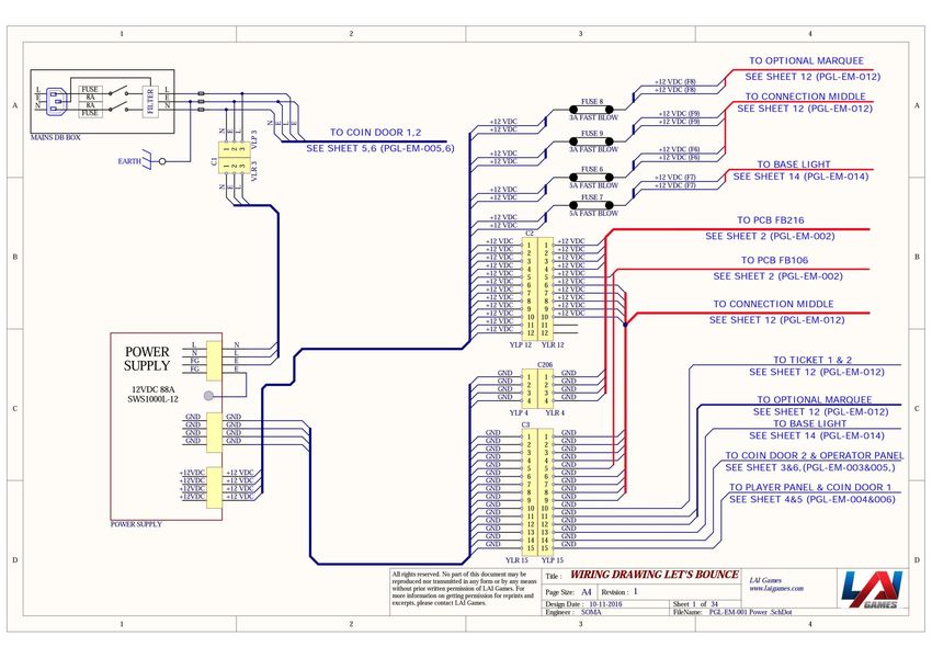
9
CONTENTS DETAILED
Stand                  Main Cabinet

Side Cabinet x2        Front Cabinet

Backboard

   10
GAMEPLAY AND MODES
OBJECTIVE
At the start of the game, the Let’s Bounce playfield is made up of all orange tiles. Each tile awards
points and turns blue after being hit. Orange tiles award more points when hit than blue. The player
is given a set number of ping pong balls and must clear all the orange tiles from the playfield in the
allocated time frame.
If there are two players, they alternate rounds.
See setting 12, Game Mode, for more information on the different game modes available.
HOW TO PLAY
Bar Mode
Pay to play
Ping pong balls are vended
Round one begins
Bounce ping pong balls off the bounce pad
Aim to hit all orange tiles
Round one time runs out
OR
All orange tiles are cleared and a mini bonus state is entered
Round two begins
Aim to hit all orange tiles
Round two time runs out
OR
All orange tiles are cleared and a mini bonus state is entered
Game ends
Arcade Mode
Pay to play
Ping pong balls are vended
Round one begins
Bounce ping pong balls off the bounce pad
Aim to hit all orange tiles
Round one time runs out
Bonus round begins
Aim to hit as many rainbow tiles as possible
Bonus round time runs out
Game ends
11ATTRACT MODE
Attract mode provides a visual and audio display while the game is not being played.
PLAY MODE
Let’s Bounce has two play modes. The standard Coin Play mode, where a coin or coins are inserted,
or Free Play mode, where no coins are necessary.
COIN PLAY
Coin Play mode is entered from Attract mode, by inserting coins in any of the two coin slots on the
front of the machine cabinet, then following the instructions in the “How to Play” section.
FREE PLAY
Free play can be set in one of three ways:
Entering the operator menu by pressing the red TEST button, then entering the game
settings. From here, enter free play settings and turn free play mode on.
For a single free game, just press the green SERVICE button once.
Push and hold the green SERVICE button for 5 seconds. This is a temporary free mode, and
the game will return to normal when reset.
12OPERATION
GAME SETTINGS
1. Coin 1 Coins per Credit Default 1, Adjustable 1 – 20
Sets the number of coins that need to be inserted in exchange for each game credit.
2. Coin 1 Games per Credit Default 1, Adjustable 1 – 20
Sets the number of games granted for each credit.
3. Coin 1 Multi Bonus Credits Default Off, Adjustable On / Off
Turn on the first stage of bonus credits for coin mech 1. Turning this setting on will activate
settings 3-1 to 3-6.
3.1. Coin 1, Stage 1, Number of Coins Default Off, Adjustable Off / 1 – 99
This sets the number of coins that need to be inserted into coin mechanism 1 to reach the
bonus credit stage 1.
This setting is only active if setting 3 is ON.
3.2. Coin 1, Stage 1, Number of Bonus Credits Default Off, Adjustable Off / 1 – 99
This sets the number of bonus credits that are given when credit stage 1 is reached.
This is the number of bonus credits given, on top of what has been paid for.
This setting is only active if setting 3 is ON.
3.3. Coin 1, Stage 2, Number of Coins Default Off, Adjustable Off / 1 – 99
This sets the number of coins that need to be inserted into coin mechanism 1 to reach the
bonus credit stage 2.
This setting is only active if 3-1 and 3-2 are active.
3.4. Coin 1, Stage 2, Number of Bonus Credits Default Off, Adjustable Off / 1 – 99
This sets the number of bonus credits that are given when credit stage 2 is reached.
This is the number of bonus credits given, on top of what has been paid for.
This setting is only active if 3-1 and 3-2 are active.
3.5. Coin 1, Stage 3, Number of Coins Default Off, Adjustable Off / 1 – 99
This sets the number of coins that need to be inserted into coin mechanism 1 to reach the
bonus credit stage 3.
This setting is only active if 3-3 and 3-4 are active.
3.6. Coin 1, Stage 3, Number of Bonus Credits Default Off, Adjustable Off / 1 – 99
This sets the number of bonus credits that are given when credit stage 3 is reached.
This is the number of bonus credits given, on top of what has been paid for.
This setting is only active if 3-3 and 3-4 are active.
4. Coin 2 Coins per Credit Default 1, Adjustable 1 – 20
Sets the number of coins in coin mech 2 input that need to be inserted in exchange for each
game credit.
5. Coin 2 Games per Credit Default 1, Adjustable 1 – 20
Sets the number of games granted for each credit from coin mech 2 input.
136. Coin 2 Multi Bonus Credits Default Off, Adjustable On / Off
Turn on the first stage of bonus credits for coin mech 2. Turning this setting on, will activate
settings 6-1 to 6-6.
6.1. Coin 2, Stage 1, Number of Coins Default Off, Adjustable Off / 1 – 99
This sets the number of coins that need to be inserted into coin mechanism 2 to reach the
bonus credit stage 1.
This setting is only active if setting 6 is ON.
6.2. Coin 2, Stage 1, Number of Bonus Credits Default Off, Adjustable Off / 1 – 99
This sets the number of bonus credits that are given when credit stage 1 is reached.
This is the number of bonus credits given, on top of what has been paid for.
This setting is only active if setting 6 is ON.
6.3. Coin 2, Stage 2, Number of Coins Default Off, Adjustable Off / 1 – 99
This sets the number of coins that need to be inserted into coin mechanism 2 to reach the
bonus credit stage 2.
This setting is only active if 6-1 and 6-2 are active.
6.4. Coin 2, Stage 2, Number of Bonus Credits Default Off, Adjustable Off / 1 – 99
This sets the number of bonus credits that are given when credit stage 2 is reached.
This is the number of bonus credits given, on top of what has been paid for.
This setting is only active if 6-1 and 6-2 are active
6.5. Coin 2, Stage 3, Number of Coins Default Off, Adjustable Off / 1 – 99
This sets the number of coins that need to be inserted into coin mechanism 2 to reach the
bonus credit stage 3.
This setting is only active if 6-3 and 6-4 are active.
6.6. Coin 2, Stage 3, Number of Bonus Credits Default Off, Adjustable Off / 1 – 99
This sets the number of bonus credits that are given when credit stage 3 is reached.
This is the number of bonus credits given, on top of what has been paid for.
This setting is only active if P6-3 and P6-4 are active.
7. Common Coin Default Off, Adjustable On / Off
If the setting is ON, coin 1 and coin 2 contribute to the same coin pool. If the setting is off, they
are counted separately.
This setting is only active is P20, Card System, is set to off.
8. Attract Sound Default 3 minutes, Adjustable Off, On, 2m, 3m, 4m, 5m, 10m, 30m
Controls the delay between the attract mode audio loop repeating.
9. Error Message Alert Default Display & Audio, Adjustable Display & Audio, Audio Only, Display
Only, Off
Controls how the game indicates an error has occurred. Errors can be shown on the display
and/or with an error voice message that is played through the speakers, or hidden completely.
10. Free Mode Default Off, Adjustable On / Off
Sets if the game requires a credit to start playing. If set to on, the game can be played for free.
1411. Prize Type Default Ticket, Adjustable Off / Ticket / Coupon
Defines the type of prize given to the player. This only affects how the jackpot number and
tickets owing number is displayed.
If set to "off" then no prize is paid out.
If set to "tickets" then prize numbers shown on displays are the same as the number of tickets
dispensed from the mech.
If set to "coupons" (1 ticket = 2 coupons), then prize numbers displayed to the player double the
number of tickets dispensed from the mech.
12. Game Mode Default Arcade, Adjustable Bar / Arcade
Defines how the game operates.
Bar: Round one and two are the same. If the playfield is cleared on either round, then an extra
bonus rainbow round is activated. There are no bonus points for reaching the Beat Score setting
value, but if the bonus round is activated, bonus tickets are added to the prize payout.
Arcade: Round two bonus rainbow round is only triggered if the player clears the playfield in
round one. If the total score is higher than the Beat Score setting value, then the Bonus Ticket
setting value is added to the prize payout.
13. Bonus Ball Default 5, Adjustable 1-10
Set how many balls are dispensed in the bonus rainbow round.
14. Game Time Default 30, Adjustable 30-60
Sets how many seconds a normal round lasts.
15. Bonus Time Default 7, Adjustable 1-60
Sets how many seconds bonus rainbow round lasts.
16. Beat Score Default 6500, Adjustable 5500-7000
Sets the total score that a player must beat to be awarded the Bonus Tickets setting value.
17. Points per Ticket Default 100, Adjustable 1-1000
Sets how many points are required to dispense 1 ticket from the mech.
18. Maximum Tickets Default 200, Adjustable 1-1000
Sets the maximum number of tickets allowed to be dispensed based on the game score.
19. Mercy Tickets Default 5, Adjustable 1-500
Activate or deactivate the card system on the machine.
20. Bonus Tickets Default 50, Adjustable 10-5000
Sets the number of bonus tickets that are awarded to the player when they meet the criteria
dependant on the game mode (setting 12).
21. Card System Default On, Adjustable On / Off
Activate or deactivate the card system on the machine.
15AUDITS
1. Total Coins 1
Shows the number of coins inserted on COIN1 input.
2. Total Coins 2
Shows the number of coins inserted on COIN2 input.
3. Total Service Credits
Shows the number of times the service button was used to issue 1 credit to the game.
4. Single Player Games
Shows the total number of single player games played.
5. Double Player Games
Shows the total number of double player games played.
6. Total Games Played
Shows the total number of games completed.
7. High Score
The highest score achieved.
8. Total Tickets
Shows the number of tickets paid out from all ticket mechs.
9. Average Tickets Per Game
Shows the average number of tickets won from each game.
10. Total Skips
The number of times the “end turn” button has been pressed.
11. Total Time Skipped
The total number of seconds of gameplay that have been skipped as a result of pressing the
“end turn” button.
12. Average Time Skipped
The average amount of game time remaining when the “end turn” button is pressed.
13. Cleared Playfield
The number of rounds where the playfield was cleared.
14. Jackpot
The number of times “bonus tickets” were won.
15. Checksum
Manufacturers audit for error checking.
16INPUT AND OUTPUT TESTS
OUTPUT TESTS
1. All Outputs
Flash all lamps, run playfield colors and player panel button lamps.
2. Tiles
Flash all playfield tile lights in order of tile 1 to 45.
3. Score
Count all seven segment displays from 0000 – 9999.
4. Lights
Flash the player one, player two, player panel buttons, round, score, clear and winner lamps.
INPUT TESTS
The display will read ON or OFF to indicate if the currently selected input is active or not.
Up Button
Down Button
Test / Enter Button
Back / Service Button
Utility Button
Single Player Button
Double Player Button
End Turn Button
Ball Sensor
Home Sensor
Player Sensor
Return Sensor
Coin 1
Coin 2
Ticket 1
Ticket 2
RUN TESTS
1. Run Ticket Mechs
Try dispense a single ticket from both ticket mechs.
2. Run Ball Dispenser Motor
Set the ball gate to the return positon and run the ball lifter motor.
3. Run Ball Gate Motor
Toggle the ball gate between the home, to playfield and to player positions.
4. Run Tile Sensor
Activate playfield tiles so they will light up when hit. Use this to check tile sensitivity.
5. Max Load
Runs all outputs at the same time at maximum power. Seven segments are set to 8888,
audio plays, all motors run and all lights turn on.
17GAME HISTORY
This menu lists the data on the last 10 game plays. Each entry lists five pieces of data:
SPL / DPL – Single player or double player game
P1 – Player one’s score
P2 – Player two’s score
T1 – The number of tickets paid out to player one
T2 – The number of tickets paid out to player two
ERRORS
Name Cause Solution
Refill the ticket mechs and ensure
there is no jam. Clear the error by
viewing it in the errors menu and
The game has run out of tickets or
Error ticket 1 pressing the right button. The
if there is a jam on ticket mech 1
game will automatically pay out
remaining tickets if there is
activity on the ticket sensor.
Refill the ticket mechs and ensure
there is no jam. Clear the error by
viewing it in the errors menu and
The game has run out of tickets or
Error ticket 2 pressing the right button. The
if there is a jam on ticket mech 2
game will automatically pay out
remaining tickets if there is
activity on the ticket sensor.
The coin sensor has been pressed Release the coin sensor to clear
Coin 1 error
for a long period of time. the error.
The coin sensor has been pressed Release the coin sensor to clear
Coin 2 error
for a long period of time. the error.
Check for and clear anything that
A button has been pressed for
Error button jam might be jamming any of the
more than five seconds.
button sensors.
18The game will try and resolve this
error by itself during attract
mode. If this fails, check for and
The ball lifter (rotating wheel) I clear any ball jams in the lifter
Error Ball Jam activated, but the sensor is not mechanism. Check for and clear
detecting any balls. anything that might be jamming
the ball lifter sensor. Check the
lifter motor by running it via the
run tests menu.
Clear the error by viewing it in
Error EEP NJ EEPROM memory related to the NJ the errors menu and pressing the
game state saving system can’t be right button.
Only applicable to New
read. If the error still occurs, the IC is
Jersey firmware
faulty and needs to be replaced
The CPU cannot read or write to its Clear the error by viewing it in
Error PSet on-board EEPROM program the errors menu and pressing the
settings, or is receiving errors right button.
This error will cause game
operation to stop
during communication with the If the error still occurs, the IC is
EEPROM. faulty and needs to be replaced.
Clear the error by viewing it in
The CPU cannot read or write to its
the errors menu and pressing the
on-board EEPROM history data, or
Error History right button.
is receiving errors during
If the error still occurs, the IC is
communication with the EEPROM.
faulty and needs to be replaced.
Set all audits to default by
viewing the error in the errors
menu and pressing the right
Error EEP Audit R The CPU cannot read or write to its button.
on-board EEPROM resettable Set resettable audits back to
This error will cause game audits, or is receiving errors during default by going into the audits
operation to stop communication with the EEPROM. menu and press and hold the
right button. If the error still
occurs, the IC is faulty and needs
to be replaced.
Set all audits to default by
Error EEP Audit UR The CPU cannot read or write to its viewing the error in the errors
on-board EEPROM unresettable menu and pressing the right
This error will cause game audits, or is receiving errors during button.
operation to stop communication with the EEPROM. If the error still occurs, the IC is
faulty and needs to be replaced.
19SECTION A: SERVICE INSTRUCTIONS
NOTE: Be sure to read the following carefully before servicing the machine.
LOCATING AND ACCESSING PARTS
The following pictures identify the location of the main serviceable items.
CABINET FRONT
1
2
3
4
5
6
7
8
9
1. Header
2. Backboard
3. Playfield
4. Bounce pad
5. Player panel
6. Coin door 1
7. Ticket door 1
8. Ticket door 2
9. Coin door 2
20BACKBOARD
1
2 1
3 3
4 4
5 5
6 6
7 7
8 8
9 9
10 11 12
1. Speakers
2. Timer display lamp
3. Player 1 and 2 lamps
4. Player 1 and 2 round 1 score lamps
5. Player 1 and 2 round 1 clear lamps
6. Player 1 and 2 round 2 score lamps
7. Player 1 and 2 round 2 clear lamps
8. Player 1 and 2 total score lamps
9. Player 1 and 2 winner lamps
10. Round 1 lamp
11. Round 2 lamp
12. Total score lamp
21PLAYER PANEL
1
2
1. Bounce pad 3 4 5
2. End turn button
3. Single player button
4. Double player button
5. Credit display
CABINET INNER
1
2
1. FB216 Game Control PCBs
2. FB106 Sound Board
1
2
1. Ball lifter
2. FB86 Sensor PCB
221
2
3
1. Ball gate sensor – player
2. Ball gate sensor – home
3. Ball gate sensor - return
CABINET REAR
3
1
4
5
2
6
1. FB63 display PCB
2. Lightboxes / lamps x12
3. Speaker crossover
4. Woofer speaker
5. Tweeter speaker
6. FB44 display PCB x6
23CABINET SIDE
1
1. FB214 Fuse PCB x5 (behind side panel)
OPERATOR PANEL / SERVICE CONTROLS
7
1
8
2
9
3
4 10
5
11
6
1. Up button
2. Back / service button
3. Test / enter button
4. Down button
5. Volume control
6. Utility button
7. Coin 1 counter
8. Coin 2 counter
9. Ticket 1 counter
10. Ticket 2 counter
11. UCL connector
24PARTS DESCRIPTION
HEADER DISPLAY
The header is a static sign illuminated by LED strip lighting.
BACKBOARD
The backboard at the rear of the game mounts the speakers, FB63 timer display, FB44 score displays,
and LED strip lamps. All components are accessible by removing the guards behind the backboard.
SPEAKERS
Two component speakers are wired to the left and right outputs from the FB106 sound board. Each
speaker pair consists of a crossover, woofer speaker and tweeter speaker.
PLAYFIELD
CAUTION: Take care when working around the playfield tiles and ensure mounting
mechanism is not damaged.
The playfield consists of 45 tiles. Each tile is a delicate assembly containing one FB205 Sensor PCB.
The FB205 is a sensitive PCB used to detect the vibration caused by a ping-pong ball hit. Extra care
should be taken when handing and cleaning so as not to damage the mounting.
Each FB205 is programmed with firmware and communicates with the FB216 using an RS485 data
bus. Ensure DIP switches on each FB205 are set so that each PCB has a unique address as defined in
the image below. Correct addressing is critical and starts as 1 and increases to 45 from left to right
and from front to back.
25Addresses are set via DIP switches using binary coding. Patterns are shown below:
ADDRESS SW6 SW5 SW4 SW3 SW2 SW1
1 ON ON ON ON ON OFF
2 ON ON ON ON OFF ON
3 ON ON ON ON OFF OFF
4 ON ON ON OFF ON ON
5 ON ON ON OFF ON OFF
6 ON ON ON OFF OFF ON
7 ON ON ON OFF OFF OFF
8 ON ON OFF ON ON ON
9 ON ON OFF ON ON OFF
10 ON ON OFF ON OFF ON
11 ON ON OFF ON OFF OFF
12 ON ON OFF OFF ON ON
13 ON ON OFF OFF ON OFF
14 ON ON OFF OFF OFF ON
15 ON ON OFF OFF OFF OFF
COUNTERS
Counters will increment for each coin inserted and each ticket paid out. Counters are under
firmware control and are not directly connected to the mechanisms.
BUTTONS
Press the green SERVICE/BACK button to issue a service credit from attract mode. Press and hold the
green SERVICE/BACK button to enter temporary Free Play Mode. This will remain in place until
machine power is reset.
Press the red TEST/ENTER button to enter the operator menu from attract mode.
When in the operator menu, use four up/down/left/right buttons to navigate through the menu.
VOLUME KNOB
Use to adjust the speaker’s sound level.
COIN MECHANISM / BILL ACCEPTOR / CARD SYSTEM
Credits can be inserted via a coin mech, bill acceptor and/or card system connection. All interfaces
are located inside the front coin doors.
TICKET MECHS
Tickets won are paid out from two ticket mechs. Being a 2-player game, tickets are paid out on the
mech corresponding to the player. Player 1 tickets are paid out on ticket mech 1 and player 2 tickets
are paid out on ticket mech 2. The exception being when the “Card System” game setting is set to
ON. If a 2-player game is played by crediting only a single player position then all tickets are paid out
on that players ticket mech.
PLAYFIELD FUSES – FB214
Each tile on the playfield receives an independent power and data connection. Each tile is fused by
the FB214 PCBs which are located behind the side panel.
26GAME BOARD – FB216
The FB216 is the main control board for the game. It contains the application firmware and output
drivers to control the lamps, displays and tiles.
SOUND BOARD – FB106
The FB106 is the sound driver board containing the sound files and amplifier. Volume is adjusted by
the potentiometer on the operator panel.
BALL DISPENSER
The ball dispenser is a 2-stage mechanism consisting of a ball lifter and a ball gate.
The lifter is a rotating plate to lift the ball to the ball gate. Balls are counted by the FB84 IR Sensor
PCB.
The ball gate is used to hold the balls before dispensing them to the player. Gate position is detected
by the FB165 sensor PCB.
POWER INLET/MAINS SWITCH
The power inlet is a standard IEC inlet socket with a mains power switch, located at the rear of the
machine. There is a main power fuse internal in this IEC socket. The fuse should be a M205, 250VAC,
8A.
WARNING: ALWAYS turn OFF mains power and unplug the game before replacing any
fuses.
ALWAYS use the correctly rated fuse.
POWER SUPPLY
The entire machine is powered by a single 600W 12V power supply. AC input is universal 85-265VAC
47-63Hz.
LAMPS
WARNING: Always turn OFF mains power and unplug the game, before replacing any
lamps.
Always replace the lamps with the same or equivalent size, wattage and
voltage.
All button lamps are 12VDC T10 LED or equivalent.
All Playfield tile lights are FB205 PCBs.
All remaining lighting is RGB LED strip.
Contact your nearest LAI Games office for replacement LED strip to ensure color is matched.
27MAINTENANCE
EXTERIOR
Regularly dust and clean the external cabinet areas as required, using a soft water-damp
cloth and mild soap.
Check for blown bulbs and replace as required.
Check all LED strips are functioning and repair as required.
Check that all playfield tiles are operating and positioned correctly. Tiles should all be at the
same level, orientation, and spacing.
Check all foam padding on the playfield cross-beam mounts is intact with no exposed metal.
Re-glue any foam that has come loose
Check below the playfield for stuck balls, clear out any obstructions to allow balls to roll
freely.
INTERIOR
Regularly dust and vacuum the interior of the cabinet, taking care to remove any objects
that may have fallen.
Check and tighten all fixing hardware and fasteners as required.
Check the ball dispenser sensors are clear, blow out any dust from the optical sensors.
Check the ball lifter is free to rotate and balls are free from obstruction.
Check the balls are clean and undamaged. Discard any balls that are cracked or deformed.
28SECTION B: TECHNICAL DETAILS
WARNING: Always turn OFF mains power and unplug the game before cleaning the interior
of the machine.
Always after cleaning the cabinet interior, check all harness connectors and restore all loose or
WARNING:
interrupted It is advised that anybody using SECTION B for repairing or modifying any of the
connections.
components of the game should be a qualified technician, having at least a
basic knowledge of digital components, integrated circuits and electricity.
POWER SUPPLY
The universal AC input power supplies generates 12VDC for the entire machine. The power supply
output voltage should be 12VDC. It can be adjusted when necessary by turning the blue adjustment
trimpot with a small Philips screwdriver.
29COIN OPTIONS REFERENCE GUIDE
By default, the coin door contains a micro switch connected to the COIN2 input for crediting the
machine.
A 9 way Molex connector has been installed on the coin door which can be optionally used to make
adaptors for most electronic coin systems and comparators.
The following picture illustrates the connector pinout.
Shell part number: Molex 03-09-1092
Pins: Molex 02-09-1119 (loose)
Molex 02-09-1117 (chain)
PIN1 = GND
PIN2 = COIN1 input
PIN3 = 12VDC
PIN7 = GND
PIN8 = COIN2 input
PIN9 = 12VDC
Contact your nearest LAI Games distributor for harnessing to suit different coin comparators and bill
acceptors.
UNIVERSAL CARD LINK CONNECTION
A 9 pin Universal Card Link connector exists on the operator panel inside the coin door.
Mating shell part number: Molex 9-pin housing: 03-09-2092
Pins part number: Wire Gauge and Terminals: 02-09-2103 (14-20 gauge wire) or 02-09-2118 (18-22
gauge wire)
Pin 1. +12v- Supply to Card System.
Pin 2. Coin 1- input to the game PCB.
Pin 3. Coin 2- input to the game PCB.
Pin 4. Coin meter 1- is connected to the coin meter 1 output from the game PCB and can be used by
card systems for monitoring purposes.
Pin 5. Coin meter 2- is connected to the coin meter 2 outputs from the game PCB and can be used by
card systems for monitoring purposes.
30Pin 6. Ticket Meter- is connected to the Ticket 1 Meter output from the game PCB and can be used
by card systems for monitoring purposes.
Pin 7. Empty
Pin 8. Empty
Pin 9. Ground- is connected to the common Ground connection, the same ground as the Game PCB.
TICKET MECHANISMS
2 x ticket mechs can be fitted inside the ticket doors. Connections are available through a standard 4
way Molex receptacle. Deltronic DL-1275 mechs are installed by default.
Shell part number:
Molex 03-09-1042
Pins:
Molex 02-09-1119 (loose)
Molex 02-09-1117 (chain)
PIN1 = NOTCH
PIN2 = GND
PIN3 = DRIVE
PIN7 = 12VDC
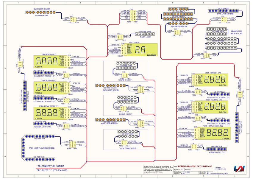
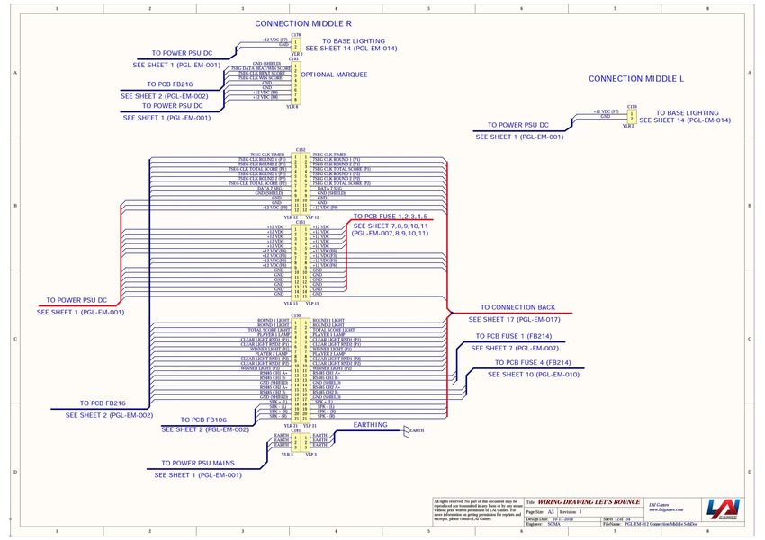
31WIRING DIAGRAMS (Next Page) 32
33
34
35
36
37
38
39
40
41
42
43
44
45
46
47
48
49
50
51
MECHANICAL ILLUSTRATIONS
MAIN ASSEMBLY

52
FRONT PANEL

53
PANEL DOOR AND BASE FRONT PANEL

54
COIN DOOR AND TICKET DOOR

55
COIN PLATE WITH DBA AND CASH BOX

56
OPERATOR PANEL AND POWER SUPPLY

57
PLAYER PANEL

58
RIGHT AND LEFT PLAYER PANEL STOPPER

59
BALL GATE AND DB BOX

60
BALL GATE MOTOR AND DISPLAY SIGN

61
BALL LIFTER AND BALL HOPPER CHUTE

62
DISPLAY PANEL AND BASE DISPLAY PANEL

63
BASE SCORE PANEL

64
BOARD DISPLAY ROUND 1 AND BOARD DISPLAY ROUND 2

65
RIGHT AND LEFT SIDE WALLS

66
MAIN PLAYFIELD, BEAM FOUR TILES AND BEAM FIVE TILES

67
Disclaimer
OPERATOR, PLEASE NOTE

By accepting delivery of and placing this hardware and licensed software into operation, the
Operator represents and warrants that it will only operate the hardware and licensed
software provided by LAI Games in compliance with the regulatory requirements of the
country, state, and/or municipality in which the hardware and licensed software are used
and/or operated. LAI Games has provided this hardware and licensed the software only for
legitimate and legal use, and any use of the hardware and licensed software in a manner
that violates any laws of the country, state, and/or municipality in which the hardware and
licensed software are used and/or operated is wholly unauthorized and shall be at
Operator’s sole and complete risk.

Operator assumes any and all risk and liability for any civil or criminal legal claims or causes
of action arising from the unauthorized use and/or operation of the provided hardware and
licensed software, such improper and unauthorized use specifically including, but not
limited to:

     (a) Operating or allowing the operation of the hardware and licensed software in a
         manner that violates the laws and regulations of the country, state, and/or
         municipality in which the hardware and licensed software are used or operated;

     (b) Assembling or causing the assembly of the hardware in a manner not authorized by
         or disclosed in this manual;

     (c) Any tampering with, changes to, or modifications of the licensed software that occur
         after the software leaves LAI Games’ factory that is not made by authorized LAI
         Games personnel and that is directly or indirectly caused by Operator; and

     (d) Any tampering with the computer chip/electronic programmable read only memory
         (EPROM) by or on behalf of Operator that directly or indirectly causes the tamper-
         indicating holographic seal on the computer chip/EPROM to be broken or damaged
         in any way.

LAI Games shall have no liability related to such improper and unauthorized use and/or
operation of the hardware and licensed software, and Operator shall indemnify, defend,
and hold LAI Games harmless for any claim or cause of action brought against LAI Games
arising from Operator’s or Operator’s representative’s improper and unauthorized use
and/or operation of the hardware and licensed software.

Any improper and unauthorized use shall completely and totally void any and all warranties,
both express and implied, of the hardware and licensed software provided by LAI Games.

68
WARRANTY LAI Games warrants its manufactured products for a period of 3 months inclusive of parts and labor from the date of sale. LAI Games exclusive obligation is to repair any item with any defects as a result of faulty workmanship or materials, providing the defective item or items of equipment are returned to the LAI Games distributor from which the machine was purchased. LAI Games shall have no obligation to make repairs necessitated by negligence or interference to any component by any unauthorized personal. This will automatically void any existing warranty. IF MAKING A WARRANTY CLAIM: (a) A copy of the sales invoice must accompany the claim. (b) To and from transport and freight costs are not covered by the warranty. (c) Warranty is not transferable with the sale of a machine from one owner to another. 69
Contact Us
Sales and Enquiries:   sales@laigames.com
Technical Support:     support@laigames.com
Website:               www.laigames.com

           For your nearest LAI Games Distributor, visit our web site at
                           www.laigames.com

70
You can also read