GSM Auto-Dialer Installation & User Guide (model APD-G05) - ITWatchDogs, Inc. 7600 N. Capital of Texas Hwy. Suite B-345 Austin, TX 78731
←
→
Page content transcription
If your browser does not render page correctly, please read the page content below
GSM Auto-Dialer
           (model APD-G05)
           Installation & User Guide

ITWatchDogs, Inc.               http://www.itwatchdogs.com
7600 N. Capital of Texas Hwy.
Suite B-345                     Tel: (512)-257-1462
Austin, TX 78731                Fax: (309)-406-3651
USA
APD-G05 GSM autodialer
While the WeatherGoose monitor series provides IT administrators and facilities managers with a powerful
combination of e-mail and SNMP-based alerts – what happens if your network connections go down and the
messages can’t be sent? Models equipped with dry-contact relays, such as the RelayGoose-II, can even trigger
alarm lights or sirens via the relay outputs – but what if there’s no one around to hear or see them?
The APD-G05 GSM autodialer provides another option. When combined with an ITWatchDogs monitoring
unit equipped with output relays, such as a RelayGoose-II, the APD-G05 can be programmed to call up to nine
different phone numbers and play a pre-recorded message to each person who answers, until one of them
acknowledges the message by pressing the * or # key on their phone, whenever it is triggered by the monitoring
unit’s output relays. The unit can also be programmed to send SMS messages rather than voice, can play one of
two different messages, depending on which trigger input is activated, and can call certain numbers for one trigger
vs. another. It also has a built-in audible alarm, is able to dial out even while running on battery power, and can
be programmed to send out a periodic “test” message to verify that the unit is operating properly.APD-G05 GSM autodialer
Your APD-G05 GSM autodialer should have come with the following items included in the box:
Ÿ (1) APD-G05 Autodialer
Ÿ (1) 7.2V NiMH battery pack (older models only; newer models use a standard 9V battery instead)
Ÿ (1) 12Vdc power supply
Ÿ (2) drywall anchors and matching screws.
In addition to the items in the kit, to install the APD-G05, you will need (at minimum):
Ÿ an activated SIM card (the unit can use both monthly-contract and prepaid-account cards)
Ÿ at least one length of 2-conductor alarm wire, to connect the APD-G05 to the dry-contact relay terminals on
the relay outputs.
Ÿ appropriate tools (Philips and flat-head screwdrivers, drill, ruler, stud finder, etc.) to mount the unit on the
wall and to connect the wires to the terminal block
Ÿ a 9V alkaline battery, if yours is one of the newer models which doesn’t come with the NiMH battery pack
Before you proceed, make sure you’ve chosen an appropriate spot to mount the autodialer; ideally, it should
be located conveniently near an AC power socket, high enough on the wall to be easily operated, in an area where
the unit can get good cell-phone reception. Don’t worry too much about the distance between the autodialer and
the monitoring unit; since the trigger is just a dry-contact relay signal, the trigger signal is essentially immune to
interference from induced EM or RF noise, so the wiring between the autodialer and the monitoring unit can be
dozens, or even hundreds of feet if necessary. (Just make sure the wiring is routed such that no one can trip over
it, and that it can’t get crushed or damaged by equipment rolling over it!)
When choosing a spot for mounting, make sure that there is no electrical wiring or plumbing running behind
the wall in the spot where you intend to drill holes for the drywall anchors. You should also check the cell-phone
signal reception in that spot, by holding your own cell phone up against the wall in the intended mounting space
to see how many “bars” you get; if your cell phone’s reception is poor, then the APD-G05’s reception will also
be poor, and the unit may not work reliably in that location.
160mm
An example of mounting the APD-G05 GSM autodialer unit to
the wall is shown here. The mounting holes should be drilled
160mm apart, using a drill bit just slightly smaller than the
diameter of the drywall anchors; push the anchors into the
holes, then use a philips-head screwdriver to screw the included
fixing screws into the anchors. Make sure you leave about
2~3mm of the screw body protruding from the anchor, so that
the APD-G05 can be hung onto the screw heads.
Also, be sure to make all of the necessary electrical
connections, including connecting the 7.2V NiMH battery
pack, before hanging the unit on the wall.Before you mount the APD-G05 to the wall, turn it over so that you are looking at the back of the unit:
ANTENNA
ANTI-TAMPER SWITCH SPEAKER
TAMP TR2 TR1 0V 12V+
SIM CARD COMPARTMENT BACKUP BATTERY
TERMINAL BLOCK COMPARTMENT
Both the backup-battery and SIM card compartments are secured with a small Philips-head screw. There is
also a raised ridge on the battery-compartment door to provide some friction-lock, so be careful when removing
or replacing the cover. For now, go ahead and remove the cover, but do not connect the battery pack just yet.
Instead, remove the pack and set it aside along with the cover and locking screw.
In addition to the battery pack and connector, you will find a small switch marked “NORMAL / ERASE”
Make sure this switch is in the “NORMAL” position.
To hook up the trigger and anti-tampering signals from the monitoring unit’s relay outputs to the APD-G05
autodialer, you will need at least one length of 2-conductor wire – while we recommend using 2-conductor
alarm-panel wire such as Coleman Cable part# 511014501, Belden Wire & Cable part# 82442 8771000, or
equivalent, any plain old 22 AWG copper wiring will suffice. Examples of these connections will be shown on
the following pages, along with instructions on how to install the SIM card, backup battery, and power supply.Installing the SIM card:
The first thing to do, even before connecting the power supply or trigger wiring, is to install the SIM card.
The APD-G05 can accept either monthly-contract or pre-paid (“pay-as-you-go”) SIM cards and accounts, so the
choice of cell-phone carrier and service is up to you. (Note that if a pre-paid SIM is used, we recommend
programming the unit to make periodic “self-test” calls to keep the pre-paid account “live”; see the section on
programming the card for more details.) However, keep in mind that some pre-paid accounts – usually the types
associated with so-called “disposable” phones – may be more difficult to use with the APD-G05 than others; in
particular, if the carrier requires you to use the phone itself to add extra minutes to the SIM card, by placing the
phone into a special “refill mode” and typing in lengthy strings of code numbers, you will not be able to perform
this operation from the APD-G05; instead, you’ll have to remove the SIM card from the unit and put it back into
the phone every time you wish to top up the card.
To insert the SIM card:
1. Remove the locking screw from the SIM card cover and flip the cover open, as shown below, to
expose the SIM card slot and card holder.
2. Slide the SIM card holder back and flip it open to expose the card slot and contacts. Be careful not to
apply too much force to the card holder, or to touch the contacts.
3. Insert the SIM card into the slot, with the card’s contacts facing downwards and the beveled corner at
the top right, as shown.
4. Close the SIM card holder and slide it back into the locked position, then replace the SIM card cover
and its locking screw.
TAMP TR2 TR1 0V 12V+
SIM
SIMConnecting the anti-tamper switch signal:
The terminals marked TAMP are an NC (Normally-Closed) dry-contact pair, intended for connection to a
building-alarm panel. These contacts will remain closed as long as the unit remains mounted to the wall, keeping
the anti-tamper switch depressed; if anyone attempts to physically tamper with the APD-G05 unit by removing it
from the wall, the anti-tamper switch will be released and the TAMP contact pair will open.
IMPORTANT NOTE:
TAMP TR2 TR1 0V 12V+
if this anti-tamper function is not going to be used,
the TAMP terminals should be jumpered together
with a short piece of wire, as shown here.
Whether or not you wish to use this function is up to you; if you do, then you should run a length of
2-conductor alarm wire back to your alarm panel. (You could also, of course, run this signal back to one of the
Analog Inputs on the monitoring unit itself, if you wish.) If not, you should jumper the two TAMP terminals
together with a short piece of wire, as shown below.
security TAMP TR2 TR1 0V 12V+
if the anti-tamper function is desired, run a
alarm 2-conductor pair back to your alarm panel,
panel as shown here, back to any input which is
designed to trigger the security alarm when
contact is broken.
any attempt to tamper with the unit by removing
it from the wall or cutting the alarm wire will set
off the building security alarm
note, however, that this anti-tamper function is
only activated by the spring-loadedswitch on the
back of the unit; it will not activate if the power
supply or phone cord are cut or disconnected.Connecting the trigger signals:
The terminals marked TR1 and TR2 are dry-contact triggers which will activate the APD-G05 autodialer.
Each of these inputs functions independantly, allowing you to program the autodialer to dial one of two different
lists of numbers and deliver one of two different recorded messages depending on which input is triggered. Used
in combination with dry-contact relay-equipped ITWatchDogs monitoring unit you could, for example, have the
autodialer call a different set of numbers for a detected water leak on the floor vs. an over-temperature condition
in the room; or, you could use a single autodialer in combination with monitoring units located in different racks
to deliver a different alarm message specific to which rack’s monitoring unit triggered the alarm. Some examples
of these applications will be shown below.
The TR1 and TR2 inputs are triggered when a contact closure grounds the input to 0V, which means that these
inputs should be connected to the NO (Normally Open) contact pairs of the monitoring unit. (For purposes of
illustration, these examples will assume the use of a RelayGoose-II monitoring unit; however, the APD-G05
autodialer can be used with any ITWatchDogs monitoring unit or accessory equipped with appropriate dry-
contact relay outputs.)
Example #1: One relay output, one trigger input
The simplest application, of course, is using a single trigger input in combination with a single output from a
single monitoring unit (in this example, a RelayGoose-II). Note that since the relay outputs on an ITWatchDogs
monitoring device are true dry-contacts, you will need to bring the 0V (or DC ground) over from the APD-G05
autodialer terminals as well as the TR1 trigger signal, as shown here.
RELAY 1 RELAY 2 RELAY 3
NC C NO NC C NO NC C NO
TAMP TR2 TR1 0V 12V+
relay 1 de-energized
(no alarm condition)
When wired as shown above, any alarm event associated with RELAY 1 in the RelayGoose-II will energize
the relay, closing the circuit and activating the autodialer sequence. (Instructions on how to set alarms and
associate them with the relays can be found in the Setup Guide & User Manual for your particular model of
monitoring unit or accessory.)
RELAY 1 RELAY 2 RELAY 3
NC C NO NC C NO NC C NO
TAMP TR2 TR1 0V 12V+
relay 1 energized
(unit is in alarm condition)
completes the circuit and
triggers the autodialerExample #2: Using both trigger inputs from a single monitoring unit
As mentioned previously, the APD-G05 can be programmed to call different lists of phone numbers, and play
a different recorded message, depending on which of its two trigger inputs are activated. This allows you to
selectively determine which employees, facilities managers, or maintenance contractors are alerted to a problem
at the facility, depending on the nature of the alarm.
An example of this kind of connection is shown here. Note that instead of running two pairs of wires from
the autodialer to the relay outputs, we’ve only run a single 0V (DC ground) wire (shown in black) from one to the
other, then jumpered the two “C” terminals together at the RelayGoose-II’s terminal block. The primary reason
for this is that the terminals on the APD-G05 autodialer are smaller than the ones on the relay output terminals,
with less room for multiple wires to be inserted into a single terminal, so you will probably find it much easier to
make this connection on the larger relay terminal block instead – especially since the (–) side of the DC power
supply also has to be connected into the 0V terminal at the APD-G05 side. If the alarm-wire pairs are thin enough,
though, there’s no reason not run two complete wire pairs between the APD-G05 and the monitoring unit to keep
the wiring simpler and more consistent.
RELAY 1 RELAY 2 RELAY 3
NC C NO NC C NO NC C NO
TAMP TR2 TR1 0V 12V+
In this way, any alarm event associated with RELAY 1 will activate the dialing sequence and voice message
associated with TR1, while any alarm event associated with RELAY 2 will activate the dialing sequence and
voice message associated with TR2. (These assignments are, of course, completely arbitrary; you can use any of
the monitoring unit’s NO (Normally Open) relay outputs to trigger any of the APD-G05 autodialer’s inputs, in
whatever arrangement is most convenient to you.)Example #3: Using a single dialer with two monitoring units
A third possibility, for larger facilities that require more than a single monitoring unit, is to connect the relay
output of two different monitoring units, one to each trigger input. By recording an appropriate message for each
trigger, the dialer can then inform the recipient(s) of the call which relay outputs triggered the alarm.
Note that you will probably have the same issue here as in the previous example, when it comes to getting all
of the wires to fit into the 0V terminal – namely, that unless the wires are particularly thin, you may have trouble
getting all of the necessary connections to fit in the terminal. You might need to use a secondary terminal
connection, such as a wire nut or a crimp block, to reduce the multiple wires down to a single connection.
RELAY 1 RELAY 2 RELAY 3
NC C NO NC C NO NC C NO
TAMP TR2 TR1 0V 12V+
RELAY 1 RELAY 2 RELAY 3
NC C NO NC C NO NC C NO
Alternatively, by wiring the relay outputs in parallel, it is possible to trigger one APD-G05 from multiple
monitoring units. As a practical matter, however, the wiring necessary to let more than a couple of monitoring
units share one autodialer is likely to become complicated and difficult to manage, so as a general rule we would
not recommend it.Connecting the backup battery:
To install the battery pack (included), simply use a small Philips-head screwdriver to remove the single
locking screw holding the battery compartment cover in place, then slide the cover off the back of the APD-G05
body to expose the battery compartment. Depending on when your particular dialer was manufactured, you will
find one of two things inside:
Some models use a 7.2V NiMH battery pack. If yours is
one of those, then the battery pack is typically found already
inside the battery compartment. These dialers are shipped with
the battery disconnected from the unit. To connect the battery,
simply insert the pack’s 2-pin connector plug into the matching
socket inside the compartment (the plug is polarized, and will TAMP TR2 TR1 0V 12V+
only fit one way, so don’t force it), then place the battery pack
inside the compartment and replace the cover and locking
CYCL OTRON
screw. (You will also see a switch marked NORMAL / NiMH Battery
7.2V
ERASE inside the battery compartment; make sure it is in the
NORMAL position.) ON
OTaRttery
L
CY C HB
If the connector is installed correctly, and the battery pack NiM V
7.2
is charged, the APD-G05 autodialer should beep. (If not, check
the connection; if the connection is secure, the pack probably
just needs to be charged. Charging will occur automatically
while the unit is running from the AC power adapter.)
If your APD-G05 dialer did not come with a 7.2V battery
pack as shown above, then it is the type which uses a 9V
alkaline battery instead. Simply attach the 9V battery to the
clip (making sure to observe the correct polarity), then place TAMP TR2 TR1 0V 12V+
the battery inside the compartment and replace the cover and
locking screw. (You will also see a switch marked NORMAL
CYCL
/ ERASE inside the battery compartment; make sure it is in the +
OTRON
NORMAL position.)
–
+
CY C
If the battery is installed correctly, the APD-G05 autodialer
L
OTR
–
will beep when the connection is made.
ON
In either case, the backup battery should be inspected
periodically, even if the dialer is not showing the “Low
Battery” icon on its display, to insure correct operation of the unit. If the battery doesn’t look right (discolored,
swollen, leaking, visible corrosion around the terminals, etc.), or if the “Low Battery” icon shows on the display
even while the unit is running on AC power, the battery should be replaced. If your dialer is the type that uses
9V alkaline batteries, it would also be good practice to replace the battery once a year just on general principles.
(The NiMH battery pack should last for several years before needing replacement under normal circumstances.)
Before replacing the battery, make sure the unit has been turned from the keypad – but do not
disconnect the AC power adapter from the wall socket! If both power sources are disconnected at the same time,
the unit may forget its programming before you can reconnect the new battery. Note also that if you have
connected your APD-G05’s anti-tamper loop switch to your building-alarm panel, the anti-tamper switch will
activate when you remove the unit from the wall, so you should make sure the security alarm is temporarily turned
off beforehand.Connecting the AC power adapter:
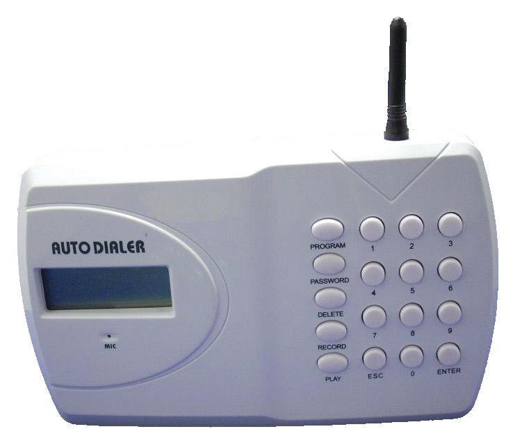
The last item to be connected to the APD-G05 unit is the AC power adapter. The autodialer is powered by a
standard 12VDC wall transformer-style power supply, similar to the one shown here, which is included with the
APD-G05 kit. Note that while the standard AC power adapter included with the kit has a U.S.-style plug for
120VAC/60Hz operation, it is actually capable of worldwide voltage (100 ~ 240VAC) and line-frequency (50 /
60Hz) operation. It is also compatible with power strips which provide 208VAC via IEC C-13 sockets connected
across two phases of a 3-phase power system, which are becoming increasingly common in larger IT installations;
all that is required is the appropriate plug-and-socket adapter. Power supplies with non-U.S. plugs may also be
available as an option; check with ITWatchDogs’ sales department for more details.
The model included in the APD-G05 kit comes with two bare wires at the end, pre-stripped and tinned for
insertion into the screw terminals. The proper connection is shown below:
TAMP TR2 TR1 0V 12V+
unstriped wire is striped wire is
negative (–) and positive (+) and
goes to 0V terminal goes to 12V terminal
IMPORTANT NOTE!
If the AC power adapter which comes with your APD-G05 kit should happen to
come with tags attached to the wires which indicate a different polarity than
the one shown here, be sure to follow the polarity indicated on the tags! (While
the wire-color scheme shown above is fairly standardized among plug-in power
supply manufacturers, it is always possible that one of the several vendors from
which we purchase these power supplies may not follow this standard.)
Once the AC power adapter has been connected, mount the autodialer onto the wall, making sure the
anti-tamper switch is pressed in. You can now start programming the autodialer, as directed in the next section.APD-G05 GSM autodialer
Now that you have the APD-G05 GSM autodialer connected and mounted to the wall, it’s time to program it
to dial phone numbers and play back a recorded message in response to trigger signals.
Note that unless specified otherwise, the APD-G05 must be in the , or inactive mode, for any
programming operations. If this is your first time programming the unit, it should come up by default; if
the LCD display shows instead, key in the four-digit password and press ESC to switch to mode.
In the following instructions, whenever it is necessary to enter the four-digit password, we will indicate this
as [x][x][x][x]. Out of the box, the factory default is 1 2 3 4 ; later, we will see how to change this, but
if this is your first time programming the unit, just leave it at the factory default for now.
Once you begin any programming sequence, if no key is pressed for 30 seconds, the unit will automatically
abort the operation and exit programming mode.
Recording voice messages:
One of the first operations you should perform is to record the alert messages you wish to have played when
the autodialer is triggered. The APD-G05 allows you to have separate messages for each of the two trigger inputs.
1. Key in the four-digit password [x][x][x][x].
2. Press [RECORD]
3. Press [1] to record the message for Trigger 1, or [2] to record the message for Trigger 2
4. Press [ENTER] to begin recording. You now have up to 10 seconds to record your message.
5. Press [ENTER] again to stop recording and save the message.
Playing back recorded voice messages:
Once you have recorded the messages, you can play them back to verify the recording.
1. Key in the four-digit password [x][x][x][x].
2. Press [PLAY]
3. Press [1] to play the message for Trigger 1, or [2] to play the message for Trigger 2
4. Press [ENTER] to play back the message.Programming phone numbers:
The APD-G05 allows you to program up to nine phone numbers into the unit to be dialed when one of the
trigger inputs is activated. Note that this sequence does not select which phone numbers are dialed; it simply lets
you set up the “phone book”, as it were, of numbers which can be dialed. Selecting which numbers are actually
dialed when a particular trigger is activated will be done in a following section.
1. Key in the four-digit password [x][x][x][x].
2. Press [PROGRAM][3][ENTER] to select “phone number programming” mode.
3. Press a number from 1 to 9 and press [ENTER] to select which of the 9 phone-number presets you wish
to program.
4. Now key in the phone number to be dialed. Each phone number can be up to 32 digits long. If you make
a mistake, use the [DELETE] key to back up and re-type the number.
5. Press [ENTER] to save the number, then [ESC] to exit programming mode.
Repeat this process as needed until you have entered all of the numbers (up to a maximum of 9) which you
want to the autodialer to be able to call once it has been triggered.
Deleting already-programmed phone numbers:
To erase a previously-programmed phone number, use the following sequence:
1. Key in the four-digit password [x][x][x][x].
2. Press [PROGRAM][3][ENTER] to select “phone number programming” mode.
3. Press a number from 1 to 9 and press [ENTER] to select which of the 9 phone-number presets you wish
to erase.
4. Press [ESC] to blank the number and exit programming mode.
Note that the APD-G05 has no provision for editing a number once it is in place (to correct a typo, for
example); if you make an error while entering the number, and don’t catch the error until after you’ve saved it as
above, you must use this sequence to delete the incorrect number and then re-enter the entire number from the
beginning.Configuring the Dialing Lists for Trigger-1 and Trigger-2:
Once you have programmed the (up to 9) phone numbers, you can determine which of these numbers are
dialed when a particular trigger is activated. This can be useful in situations where you need to notify different
personnel depending on the situation; i.e in the case of a temperature alarm, you may only want to notify the
system administrators, whereas for a water alarm you may also wish to call the building’s maintenance supervisor
or contractor.
1. Key in the four-digit password [x][x][x][x].
2. Press [PROGRAM][6][ENTER] to select “dialing list programming” mode.
3. Press [1] to set the dialing list for Trigger 1, or [2] to set the dialing list for Trigger 2, then press
[ENTER].
4. The LCD will show nine dashes, corresponding to the 9 possible phone numbers, assuming this is your
first time programming the unit; otherwise, it will show a mix of dashes and numbers, reflecting the
current programming.
5. Press a number from 1 to 9 to select which of the 9 phone-number presets you wish to enable or disable
for this trigger. Each time you press a number, it toggles that particular number on or off; enabled
numbers will display as a number, while disabled ones will display as a dash.
6. Once you have set the dialing list programmed the way you want it, press [ENTER] to save the list.
Repeat this process for both trigger inputs, if necessary. Note that you can assign any combination of numbers
to either trigger; i.e. you can have all nine numbers associated with both triggers, or only some associated with
one and some to the other, or any mix which suits your needs.
When the autodialer is triggered, it will begin dialing the numbers in the list associated with that particular
trigger, starting with the first enabled number in the list and ending with the last enabled entry. For example, if
the dialing list for Trigger 1 looks like this:
The unit will dial all nine phone numbers, starting with #1 and ending with #9. On the other hand, if the
dialing list looks like this instead:
The dialer will only dial entries #2, #4, and #7, in that order.Changing the access password:
To change the 4-digit password:
1. Key in the current four-digit password [x][x][x][x].
2. Press [PASSWORD] to select “password programming” mode.
3. The LCD will display N-P (“new password”). Enter the new four-digit password you wish to use.
4. The LCD will display C-P (“confirm password”). Re-enter the new password.
5. The LCD will display ACC (“accept”), then return to the mode to await further instructions.
Enabling or disabling the audible alarm:
The APD-G05 can sound a local audio alert when one of the triggers is activated, as well as dialing numbers.
To turn this feature on or off:
1. Key in the four-digit password [x][x][x][x].
2. Press [PROGRAM][1][ENTER] to select “audible alarm enable/disable” mode.
3. Press one of these keys to select one of the following options:
[1] to turn the audible alarm ON, or
[0] to turn it OFF
4. Press [ENTER] to save this setting and exit.
Setting the duration of the audible alarm:
The audible alarm can be programmed to sound for a fixed number of minutes before stopping. The
factory-default time is 3 minutes, but this can be changed as follows:
1. Key in the four-digit password [x][x][x][x].
2. Press [PROGRAM][2][ENTER] to select “audible alarm length setting” mode.
3. Key in the length of time (in minutes) you want the audible alarm to sound, then press [ENTER].
The audible alarm can be programmed for anywhere from 1 to 99 minutes. To prevent excessive drain on the
battery if the unit happens to activate during a main-power failure, though, we recommend that you keep the
length to 20 minutes or less, which should be more than sufficient for most applications.Setting a Trigger Delay period:
The APD-G05 can be set to wait for a given period of time, in seconds, after a Trigger Input is activated before
it begins dialing. The default setting is 00 seconds, or “dial immediately”; to change this delay period, use the
following sequence:
1. Key in the four-digit password [x][x][x][x].
2. Press [PROGRAM][4][ENTER] to select “set trigger delay period” mode.
3. Press one of these keys to select one of the following options:
[0] to set the delay to 00 seconds,
[3] to set the delay to 30 seconds, or
[6] to set the delay to 60 seconds.
4. Press [ENTER] to save this setting and exit.
Setting an Arming Delay period:
The APD-G05 can be set to wait for a given period of time, in seconds, after the unit is armed (i.e. switched
from mode to ) before the trigger inputs become active. This can be useful if one of the alarm conditions
you’ve set in the relay outputs is tied to a door switch, for example, since it will give you time to leave the room
or close the cabinets without inadvertently activating the unit. The default setting is 00 seconds, or “arm
immediately”; to change this delay period, use the following sequence:
1. Key in the four-digit password [x][x][x][x].
2. Press [PROGRAM][5][ENTER] to select “set arming delay period” mode.
3. Press one of these keys to select one of the following options:
[0] to set the delay to 00 seconds
[3] to set the delay to 30 seconds
[6] to set the delay to 60 seconds
[9] to set the delay to 90 seconds.
4. Press [ENTER] to save this setting and exit
Note that if an arming delay is set, then the symbol on the LCD display will flash during the programmed
time delay period, then come on solidly once the delay has expired.Enabling or disabling the Arming Delay countdown sound:
In conjunction with the Arming Delay period setting, above, you can also have an audible countdown sound
during the delay period. The default is “off” (no sound); to change this, use the following sequence:
1. Key in the four-digit password [x][x][x][x].
2. Press [PROGRAM][7][ENTER] to select “set arming delay sound” mode.
3. Press one of these keys to select one of the following options:
[0] to turn the delay sound OFF
[1] to turn it ON
4. Press [ENTER] to save this setting and exit.
Testing the GSM signal strength:
To test the GSM signal strength being received by the APD-G05 unit, simply press the [ENTER] key once
while the unit is in the , or inactive, mode. After a few seconds, a number between 0 and 7 will appear on
the LCD display. The higher the number, the better the reception and the more reliably the unit will operate when
it tries to make voice calls or send SMS messages.
7 is the strongest reception quality; if the number displayed is less than 2, the unit should be moved to a
different location with a stronger signal.
Checking the unit’s IMEI code:
Your cell-phone provider may require you to provide the IMEI (International Mobile Equipment Identity)
code, in order to properly activate the SIM card installed into the unit or add minutes to your account. Every GSM
device, including your APD-G05, has a unique IMEI number. If your provider requests this number, it can be
retrieved as follows:
1. Key in the four-digit password [x][x][x][x].
2. Press [PROGRAM][0][ENTER][3][ENTER][0] to select “show IMEI code”.
3. The unit’s IMEI code will be displayed on the LCD. Press [ESC] to exit and clear the display when you
are done with it.Setting voice-message or SMS-message mode:
The APD-G05 can be set to either play a voice message when each phone is answered, or to send an SMS
message to each phone number in the dialing list. To set the desired mode:
1. Key in the four-digit password [x][x][x][x].
2. Press [PROGRAM][0][ENTER][1][ENTER] to select “set alert message type” mode.
3. Press one of these keys to select one of the following options:
[0] to set “send voice message” mode, or
[1] to set “send SMS message” mode
4. Press [ENTER] to save the setting and exit.
NOTE: this is a “global” setting, which will apply to all phone numbers the unit attempts to call when
triggered! It is not possible to specify this setting on a per-phone-number basis, so that some numbers receive
voice messages and other numbers receive SMS; either everyone in the phone list gets voice messages, or
everyone gets SMS. Note also that SMS messages can only be delivered to cell phones, so if you use this mode,
make sure that none of the phone numbers in the dialing list are land lines or satellite phones or they won’t get
any messages from the autodialer when an alert occurs!
Setting the phone number displayed in the SMS message:
When the APD-G05 is set to send SMS messages, it will send the letters “SOS” followed by the phone number
specifed here. This can be any phone number you like, up to 32 digits in length. (Note that this number will not
be dialed by the APD-G05, so it doesn’t actually have to be a phone number as such; you can put in any 32-digit
numeric sequence you wish, and it will be sent along with the “SOS” message when the unit is triggered.) In
most cases, you will probably want to put in the phone number of the business or facility where the autodialer is
located, but you could also use it to provide other information, such as a facility and building number, as long as
it will fit in a 32-digit number and the recipient(s) know what the numbers mean.
To set the 32-digit SMS-message number:
1. Key in the four-digit password [x][x][x][x].
2. Press [PROGRAM][9][ENTER] to select “set SMS-message phone number” mode.
3. Key in the 32-digit phone number you want to have sent.
4. Press [ENTER] to save the message and exit.Setting the autodialer to send test messages:
Many providers of pre-paid or “pay-as-you-go” SIM cards will suspend or disable an account if that account’s
SIM card and phone does not make any phone calls within a particular period of time. (The exact period of
allowable inactivity varies between providers, so be sure to check with your particular provider for their terms of
service.) To prevent this from happening, the APD-G05 provides a “test message” feature which, when enabled,
makes the autodialer send a periodic SMS message to keep the SIM card “live” and activated.
This message, when sent, will consist of the word “TEST” followed by the 32-digit phone number
programmed above. By default, this test message will be sent every 30 days, but this can be changed to weekly,
daily, or not at all, as follows:
1. Key in the four-digit password [x][x][x][x].
2. Press [PROGRAM][0][ENTER][2][ENTER] to select “set test message interval” mode.
3. Press one of these keys to select one of the following options:
[1] to select “send every 30 days”
[2] to select “send every 7 days”
[3] to select “send daily”
[0] to select “don’t send ”
4. Press [ENTER] to save the setting and exit.
When enabled, this test message will only be sent to the first telephone number in the dialing list, not to all of
the numbers in the list. Also, it will be sent as an SMS message regardless of the “voice/SMS alerts” mode
setting, above.APD-G05 GSM autodialer
Now that you have the APD-G05 GSM autodialer programmed, let’s look at how to operate it. This section
will cover arming and disarming the unit, acknowledging phone calls when the unit starts dialing, and how to stop
the dialing sequence and reset the unit.
In the following instructions, whenever it is necessary to enter the four-digit password, we will indicate this
as [x][x][x][x]. Out of the box, the factory default is 1 2 3 4 ; if this is your first time operating the unit,
you might want to leave it as-is while you practice operating the device, but we strongly recommend that you
change it (the procedure is described in the previous section) as soon as you are comfortable using the autodialer.
Arming the autodialer:
Once the unit has been programmed, it needs to be turned , or armed, so that the trigger inputs become
active and the unit is ready to dial. Note that you must have programmed at least one message and one phone
number into the autodialer, or it will not do anything when the input is triggered!
Arming the autodialer is simple:
1. Key in the four-digit password [x][x][x][x].
2. Press [ENTER] to arm the dialer. The LCD display will change from to .
If you have programmed an arming-delay period, the indicator on the LCD will blink during the delay
countdown. During this time, the unit will not respond to the trigger inputs; once the countdown has expired and
the indicator has stopped blinking, the unit will arm itself and be ready to respond to the triggers.
IMPORTANT NOTE: You will not be able to arm the APD-G05 GSM Autodialer if one of the Trigger Inputs
is energized! (The autodialer behaves very similarly to a building-security alarm in this sense; generally, an alarm
system won’t let you arm it while one of the building doors is standing wide-open, for example.) If you attempt
to arm the autodialer while one of the triggers is already energized, the LCD will display “ ” and the unit will
remain in , or programming mode.Disarming the autodialer:
To turn the autodialer for programming, or to stop it from dialing out if one of the trigger inputs has
been activated:
1. Key in the four-digit password [x][x][x][x].
2. Press [ESC] to disarm the dialer. The LCD display will change from to .
Acknowledging the alarm when the autodialer calls (voice-message mode only):
As mentioned in the previous section, when the autodialer is triggered, it will begin dialing the numbers in the
list associated with that particular trigger, starting with the first enabled number in the list and ending with the last
enabled entry. For example, if the dialing list for Trigger 1 looks like this:
The unit will dial all nine phone numbers, starting with #1 and ending with #9. On the other hand, if the
dialing list looks like this instead:
The dialer will only dial entries #2, #4, and #7, in that order. Once the phone has been answered, if the
APD-G05 is operating in “voice-message mode” (see previous section), it will repeat the pre-recorded voice
message for that trigger up to five times; if there is no response from that particular phone, it will hang up and
then dial the next number in the sequence until all of the numbers on the dialing list have been called.
It will repeat this entire sequence three times, until one of the called phone numbers responds; if none of the
numbers have responded after the third time through the list, the autodialer will stop dialing and display
on the LCD display.
During this sequence, any of the called numbers can acknowledge the alarm and stop the dialing sequence.
To do so, press the [*] key on the telephone receiving the call; this will stop the dialing sequence and the audible
local alarm, if enabled, will also stop.
If you wish to stop the dialing sequence, but not the local audible alarm, press the [#] key on the telephone
instead, and the local alarm will continue to sound for the programmed length of time even though the dialing
sequence will stop.
Either way, the unit will remain armed, and any additional trigger event will activate the dialer again.
Note that if the unit is operating in “SMS-message mode”, the unit will simply send the SMS messages to
every phone number in the dialing list associated with the trigger input that signaled the alert, without waiting for
the recipients to send any responses. There is no provision to stop the broadcast of SMS messages to the dialing
list in mid-sequence.Resetting the autodialer to factory defaults:
If it becomes necessary to completely reset the APD-G05 autodialer to its out-of-the-box factory defaults, you
will find a switch inside the battery compartment marked NORMAL / ERASE. To erase all of the unit’s settings,
do the following steps:
1. Disconnect both the AC power supply and the phone line before removing the autodialer from the wall.
2. Open the battery compartment, and disconnect the 7.2V backup battery pack.
3. Open the SIM card compartment, and remove the SIM card.
4. Move the switch to the ERASE position.
5. Reconnect the AC power supply (but do not reconnect the battery!). The LCD display should show
in large letters.
6. Press the [DELETE] key twice; the unit should acknowledge this with a double beep.
7. Disconnect the AC power supply again, then move the switch back to the NORMAL position.
8. Replace the SIM card, and close the SIM card compartment.
9. Reconnect the battery pack, then place the unit back on the wall and reconnect both the phone line and the
AC power supply. All of the unit’s settings will have been reset back to factory default, including the
access password.
NORMAL ERASE
TAMP TR2 TR1 0V 12V+
CYCL OTRON
NiMH Battery
7.2VCare and maintenance of your APD-G05 GSM Autodialer: 1. A leaking or damaged battery pack can not only result in poor performance, but could potentially damage the unit. While the NiMH battery packs supplied with the APD-G05 are generally reliable and should not need replacement under normal operating conditions, we still recommend inspecting the battery periodically (once every 6 to 12 months is generally sufficient) as a precaution. 2. Units which use 9V alkaline batteries should have the batteries replaced once a year, at minimum, regardless of condition. 3. Avoid mounting the autodialer unit in areas that are exposed to environmental extremes such as high heat. humidity, or high levels of airborne dust or chemical vapors, as this could damage the unit or the battery pack, or cause the unit to perform unreliably. 4. If it is necessary to clean the unit, use only a damp cloth and mild household cleaning agents. Do not spray cleaning fluids directly onto the unit itself; instead, spray the cleaner onto the cloth and wipe the unit clean. Under no circumstances should the unit be cleaned with strong solvents such as turpentine, paint thinner, gasoline, etc. Some important notes about SIM cards: 1. Many “pay-as-you-go” prepaid SIM cards require you to add minutes periodically, regardless of actual use, in order to keep the account “live.” Make sure you check your service provider’s terms of service on this point, and keep the SIM card topped up at the required intervals, or your provider may suspend or deactivate the SIM card and the APD-G05 will not be able to send messages. 2. Similarly, many “pay-as-you-go” prepaid SIM cards may inactivate themselves if the device they’re installed into doesn’t make at least one call or send at least one SMS message within a given period of time. We therefore recommend that you program the first number in the dialing list to be someone’s cell phone, so that it can receive SMS messages, and enable the “send test SMS messages” feature. If this is not practical or possible, then we recommend triggering the unit every so often, as a test, to make it call at least one of the phone numbers in the list. 3. If your SIM card is PIN-code protected, you will need to enter the PIN number via the APD-G05’s keypad when you first power up the unit. You will only get three chances to enter the code correctly! If you don’t enter the correct PIN code after three tries, the SIM card will lock out and you will need to obtain a PUK (PIN UnlocK) code from your service provider to unlock the card. (If this happens, be very careful to enter the PUK code correctly because depending on your service provider’s policies, an incorrect PUK code could permanently kill the SIM card, requiring you to purchase a new one.)
You can also read