Design of an Ultra-Lightweight Autonomous Solar Airplane for Continuous Flight
←
→
Page content transcription
If your browser does not render page correctly, please read the page content below
Design of an Ultra-Lightweight Autonomous
Solar Airplane for Continuous Flight

André Noth1 , Walter Engel and Roland Siegwart2
1
    Autonomous Systems Lab, EPFL andre.noth@epfl.ch
2
    Autonomous Systems Lab, EPFL roland.siegwart@epfl.ch

Summary. The Autonomous Systems Lab of EPFL3 is developing, within the
framework of an ESA program, an ultra-lightweight solar autonomous model air-
plane called Sky-Sailor with embedded navigation and control systems. The main
goal of this project is to jointly undertake research on navigation, control of the
plane and also work on the design of the structure, the energy generation system.
The airplane will be capable of continuous flight over days and nights, which makes
it suitable for a wide range of applications.

Key words: Autonomous UAV, solar powered airplane, sustainable flight

1 Introduction

Development of unmanned aerial vehicle (UAV) has attracted the attention
of several agencies and university laboratories over the past decade, due to
their great potential in military and civilian applications.
    There are a dozen commercial autopilots (Micropilot, Procerus, etc.) which
combine tiny dimensions, low weight and quite efficient navigation capabilities.
Despite all this, they usually use limited CPU power which restricts the control
of the airplane to classic control methods like separated PID loops and doesn’t
allow the onboard execution of more complex algorithms, for example, those
of image processing.
    On the other side, there is a lot of research in Universities in various fields,
such as SLAM4 , hardware design, control, navigation, trajectory planning, etc.
But whether they are done on VTOL5 systems or fixed-wing model airplanes,
the embedded system is often over-dimensioned, compared to the airplane
itself, in order to have high computational capabilities and efficient sensors.

3
    Ecole Polytechnique Federale de Lausanne
4
    Simultaneous Localization and Mapping
5
    Vertical Take-Off and Landing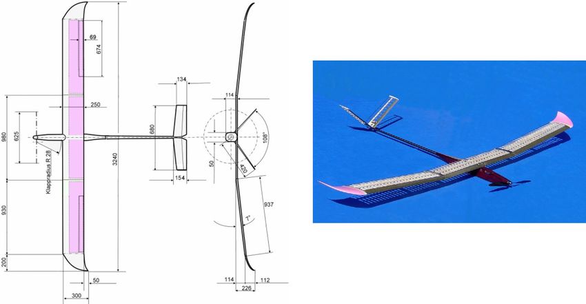
2      André Noth, Walter Engel and Roland Siegwart

Consequently, the UAV becomes very heavy, needs high electrical power and
the flight endurance reduces dramatically. Thus, endurance being one of the
most important parameters for the targeted applications, the development
and the application are not in correlation.
    In this paper, we present the airplane developed for the project Sky-Sailor
whose aim is to build a solar autonomous motor glider by taking care of all as-
pects, not only the autopilot system but as well the mechanical structure, the
solar generator, the energy storage, etc. It differs from other similar projects
like Helios or Centurion by its low weight and low cost. The final airplane only
weighs 2.5 kg and according to the AUVS-international is part of the High
Altitude Long Endurance UAV category [3].

2 Airplane Overview

2.1 Mechanical Structure

The approach we chose for the design of the airplane was to combine the
knowledge of aerodynamics engineers and the experience of lightweight model
airplanes designers. The starting point for this design was the model airplane
of Walter Engel that holds the world record for flight duration of over 15 hours
with 1 kg of battery. Sky-Sailor version 1 is basically a motor-glider with a
structural weight of only 0.6 kg for a wingspan of 3.2 m and a wing surface
of 0.776 m2 (Fig. 1). The resulting total weight including motors, propeller,
solar cells, batteries and controller is around 2.5 kg.

                   Fig. 1. Mechanical structure of Sky-Sailor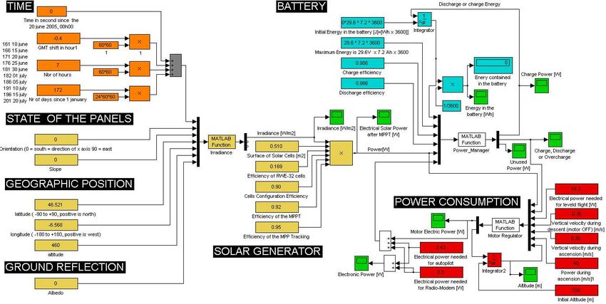
Ultra-Lightweight Autonomous Solar Airplane for Continuous Flight          3

2.2 Solar generator, Battery and Propulsion System

As explained in the introduction, one major challenge is the power manage-
ment that has to ensure continuous flight over days and nights.
    A total of 216 silicon solar cells, divided in three modules, cover an area
of around 0.512 m2 . In terms of efficiency, the better choice would have led
us to GaAs Triple Junction cells with efficiencies of 27-28 %, but taking into
account the impact of the weight on the required power for levelled flight, the
better choice is RWE-32 silicon cells with 16.9 % efficiency. Furthermore, the
flexibility of those thin cells is also an advantage for their integration on the
wing.
    The cells are encapsulated using a mechanically favorable symmetrical
laminate combined with a fiber glass reinforced plastic coating. This encap-
sulation is non-reflective. Thus, we obtain a flexible arrangement easily inte-
grable on the plane and connectable to the power circuit. At maximum sun
conditions, the available power is 28 W for each module, which makes a total
of 84 W.

     Fig. 2. Flexible solar module that can be directly integrated on the wing.

   In order to get the highest amount of energy from the solar modules, a
MPPT6 is used to charge the battery. This device is basically a high efficiency
DC/DC converter with variable and adjustable gain. One of its additional
function is to monitor the current and the voltage of each solar module and
make those information available for the central processor through I2 C.
   The energy is stored in a lithium-ion polymer battery that has a nomi-
nal voltage of 28,8 V and a capacity of 7200 mAh. The propulsion group is
composed of a Maxon DC motor, a gearbox and a carbon fiber propeller. The
required electrical power for levelled flight of Sky-Sailor is around 16 W.

6
    Maximum Power Point Tracker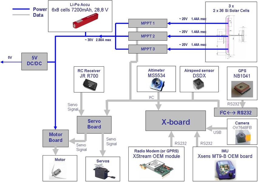
4      André Noth, Walter Engel and Roland Siegwart

3 Navigation and Control System
In order to reach the goal of the project, the autopilot design phase followed
those principles:
• select components not only according to criteria of precision and resolution,
  but as well of weight and power consumption to be suitable for the targeted
  application.
• use as much as possible digital output and calibrated sensor to reduce the
  development time and avoid additional need of A/D converter, interface
  microcontroller, etc.
• interface the sensors so that the central processor doesn’t have to wait on
  them but can access directly and rapidly to the information on request.
  This applies for example to the GPS.

3.1 Computer and Interfaces

Sky-Sailor will fly autonomously using an onboard autopilot, only high level
orders being given from the ground. The system is mainly based on a single
board computer, the X-board  which is a compact embedded PC design
for low power consumption.

          Fig. 3. X-board  single board computer from Kontron

    It includes a Geode SC1200 Processor, up to 128 Mbyte of DRAM and up
to 128 Flash storage media on board. Despite the compact size of a business
card, it offers a lot of interfaces: integrated Graphics, Ethernet, USB, RS 232,
I2 C, audio... The OS running on it is a reduced Linux distribution, based on
Debian, that only contains the necessary features.

3.2 Sensors

In Fig. 4, one can see the power generator system and the autopilot, with all
sensors and their interfaces to the X-board.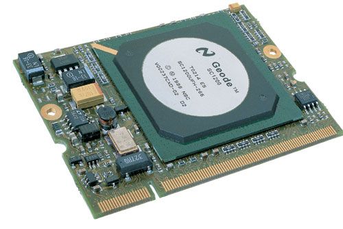
Ultra-Lightweight Autonomous Solar Airplane for Continuous Flight      5

        Fig. 4. Schematic view of the power and control parts of Sky-Sailor

Attitude

The attitude and angle rate of the airplane are given by the MT9-B IMU
7
  at a frequency of up to 512 Hz. Such a low-cost sensor is perfectly suffi-
cient to perform inertial navigation compared to heavier one [6]. It contains
accelerometers, magnetometers, gyroscopes and communicates through serial
port (RS232) with the X-board on which data fusion is executed. In the future
version of this device, the sensor fusion will be done by a DSP chip, reducing
the computational cost on the central processor of the autopilot.

VGA camera

One direction of the project is to achieve autonomous navigation based on
vision, using SLAM techniques as shown in [1] [2]. One or more lightweight
VGA cameras will give 640 x 480 images of the landscape and allow localiza-
tion and mapping of the terrain. Efforts will be done in this direction in the
following month. Cameras are connected to the central processor via USB.

Absolute x-y position and altitude

The absolute position is given by an ultra low power GPS sensor with patch
antenna from Nemerix. This sensor consumes only 61 mW for a weight of 12.36
gr. In terms of position accuracy, 95 % / 99.7 % of the time, the estimated
position lies within 2.7933 m / 4.2028 m respectively of the actual position.

7
    Inertial Measurement Unit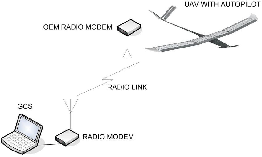
6 André Noth, Walter Engel and Roland Siegwart
A future version will accept WAAS/EGNOS correction for more precise mea-
surements. The data are sent on a serial port at a fixed rate of 1 Hz to a
microcontroller that decodes the NMEA protocol, stores the value internally
and sends them on demand to the main processor via I2 C.
The same microcontroller interfaces the altitude pressure sensor MS5534.
Pressure and temperature values, as well as four calibration factors allow the
computation of the altitude with a resolution of 1 m. The relation between
pressure and altitude being variant with the atmospheric condition, the mi-
crocontroller will achieve data fusion, using the GPS altitude as an absolute
value to correct the drift of the MS5534.
Airspeed
The airspeed sensor DSDX is a differential pressure sensor, with digital I2 C
readout and temperature compensated. It is connected to a Pitot tube fixed
at the attack border of the wing.
3.3 Ground Control Station
The control of the airplane is executed onboard but there is a link to a ground
control station through a serial radio modem that allows a baudrate of 9600
bps. The goal is to:
• download and upload airplane and control parameters, but as well the
flight plan, before the takeoff,
• get a visual feedback of the state of the airplane once airborne, modify
flight plans on-the-fly,
• retrieve and record the telemetry for flight analysis, system identification,
etc.
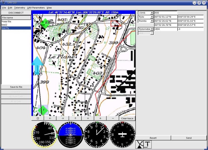
Fig. 5. Ground control station and it’s graphical user interface
The GUI8 was developed with QT graphical libraries under Linux (Fig.5).
It is composed of three main layers which ensures modularity:
8
Graphical User Interface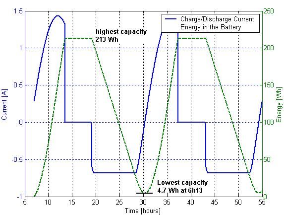
Ultra-Lightweight Autonomous Solar Airplane for Continuous Flight    7

• the graphical interface, that allows a visual overview of the state of the
  airplane and its position on a 3D map of the terrain.
• a second layer which processes data and control the GUI
• a communication module that receives and sends the data in packets to
  the airplane through the serial port connected to the radio modem.

Control of the airplane from the ground

As shown in Fig. 4, the commands given to the servos can come from the au-
topilot or a human pilot on the ground using an RC transmitter. The ”servo
board” decodes the PPM9 from the RC source and get the value given by
the autopilot through the I2 C bus. Based on one additional channel on the
RC remote, it switches from one source to the other. It is also possible, for
control tuning purpose, to mix sources and, for example, allow the autopi-
lot to command only the elevator while the other actuators are commanded
manually.

3.4 Autopilot Design Results

The final design leads us to a navigation and control system with a total mass
of 140 g for a consumption of around 4 W. One can see that 6/8 of the power
is used by the X-board and 1/8 for the transmission, the rest being used by
the sensors.

                    Table 1. Autopilot power and mass distribution

             Part                    Weight [g] Power consumption [W]
             X-board                 22        3.00
             Mother Board            22        -
             IMU                     14.5      0.21
             VGA Camera              0.55      0.1
             GPS                     12.4      0.061
             Altitude sensor board   2         0.03
             Airspeed sensor board   3         0.03
             Radio-modem             24        0.5
             Antenna                 19.6      -
             Cables, connectors      20        -
             Total                   140 g     3.93 W

   Globally, the autopilot represents 5% of the total mass of the airplane and
uses 20% of the power.

9
    Pulse Period Modulation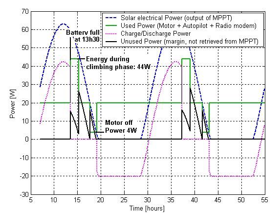
8       André Noth, Walter Engel and Roland Siegwart

4 Simulation of the solar flight
For the validation of a long endurance solar flight, a simulation was real-
ized under Matlab Simulink. Fig.6 represents the schematic of the model that
includes first the irradiance model based on [12] and depending on the geo-
graphic position, time and solar panels orientation. We then take into account
the surface of solar cells, their electrical efficiency and the efficiency of the con-
nection configuration. For the MPPT, the electrical and algorithm efficiencies
are taken into account. The power consumption is the addition of the autopi-
lot power and the power needed for flight, which was measured in the case of
levelled flight and climbing phase. Depending on the irradiance conditions and
the consumption, the battery is charged or discharged, taking into account the
efficiency of the energy transfer.

        Fig. 6. Schematic of the simulation model under Matlab Simulink

4.1 Study of various scenarios

The simulation environment allows to test different flight strategies in order
to accomplish a long endurance flight and analyze the benefit of a climbing
phase or the influence of the other parameters on the feasibility of a multi-days
flight. We will present here two scenarios.
    In the first simulation, Sky-Sailor starts a flight at EPFL location on the
21th of June with an empty battery, keeping always the same altitude. The two
graphs below show the evolution of the power distribution during 48 hours.
    With good sun conditions, the battery is fully charged at 13h30. At this
moment, the MPPT measures that the battery voltage reaches the maximum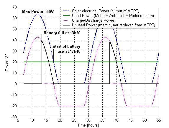
Ultra-Lightweight Autonomous Solar Airplane for Continuous Flight          9

          Fig. 7. Power distribution on Sky-Sailor during levelled flight

    Fig. 8. Battery charge/discharge current and energy during levelled flight

voltage of 33.7 [V] and adapts the maximum power point to avoid overcharge.
In this phase, the total amount of energy that is not used but that could
be retrieved from the solar panels reaches 92.5 [Wh]. During the night, the
battery supplies the all airplane but at 5h10 it is totally discharged.
    Another strategy is to better use the energy after the battery charge by
increasing altitude. Fig. 9, 10 and 11 show the same scenario presented before
but with a climbing phase until 2000 [m].
    Basically, Sky-Sailor uses the additional energy to gain altitude at 0.3
[m/s] using an electrical power of 40 [W]. Having reached 2000 [m], it stays at
this altitude until the energy is not sufficient anymore for levelled flight. At
this point, the motor is turned off and the descent starts. Finally, at the most
critical point at 6h13 in the next morning, the battery still has a capacity of
4.7 [Wh] and the charging process starts again. Globally, the unused energy
during the day is 61.5 [Wh].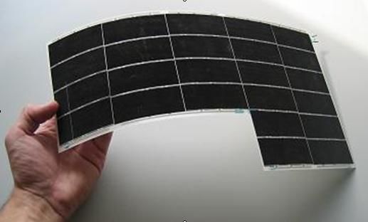
10      André Noth, Walter Engel and Roland Siegwart

     Fig. 9. Power distribution on Sky-Sailor during flight with climbing phase

                Fig. 10. Altitude during flight with climbing phase

Fig. 11. Battery charge/discharge current and energy during flight with climbing
phase
Ultra-Lightweight Autonomous Solar Airplane for Continuous Flight 11
5 Status of the Project and Future Work
The mechanical structure of the airplane is actually ready, it has been success-
fully tested and validated in terms of power and stability. The solar generator,
composed of the solar modules and the MPPT, is in the integration phase on
the wing.
Concerning the autopilot, the different parts of the system are being as-
sembled and all functionalities will be tested during the first half of this year.
In the summer, we should have achieved many flights and experiments to
clearly evaluate the capabilities of our UAV.
6 Potential Applications
Small and high endurance UAVs find uses in a lot of varied fields, civilian or
military. The civil applications, leaving side the military ones, could include
coast or border surveillance, atmospherical and weather research and predic-
tion, environmental, forestry, agricultural, and oceanic monitoring, imaging
for the media and real-estate industries, and a lot of others. The target mar-
ket for the following years is extremely important [11].
The great advantages of Sky-Sailor compared to other solutions would be
without any doubt its capability to remain airborne for a very long period, its
low cost and the simplicity with which it can be used and deployed, without
any ground infrastructure for the lunch sequence.
As an example, in the hypothetical case of forest fire risks during a warm
period, a dozen Sky-Sailor, easily launched with the hand, could efficiently
monitor an extended surface, looking for fire starts. A fast report would allow
a rapid intervention and thus reduce the cost of such disaster, in terms of
human and material losses.
Sky-Sailor would be as well a very interesting platform for academic re-
search, in aerodynamics or control.
7 Conclusion
In this paper, the design of an ultra-lightweight UAV was presented, including
details about it’s mechanical structure, the solar generator and the autopilot
system. The approach adopted doesn’t aim only at building an efficient autopi-
lot, but also keeps in mind it’s future application. This is done by designing
and selecting all the parts to obtain a lightweight and low-power airplane. We
plan to perform the first experiments with the autonomous airplane during
the first half of this year and a long endurance flight this summer.12 André Noth, Walter Engel and Roland Siegwart
8 Acknowledgement
The authors would like to thank all the people who contributed to the defi-
nition study, Samir Bouabdallah for fruitful discussions and advices on flying
robots, Walter Engel for the realization of the mechanical structure and all
the students who worked or are working on this project.
References
1. Davison A J (2003) Real-time simultaneous localization and mapping with a
single camera, IEEE Int. Conf. on Computer Vision, ICCV-2003, pp. 1403-1410,
Nice (France), October 2003
2. Lacroix S, Kung I K (2004) High resolution 3D terrain mapping with low alti-
tude imagery, 8th ESA Workshop on Advanced Space Technologies for Robotics
and Automation (ASTRA’2004), Noordwijk (Pays-Bas), 2-4 Novembre 2004
3. Eisenbeiss H (2004) A mini unmanned aerial vehicle (UAV): system overview
and image acquisition, International Workshop on ”Processing and visualization
using high-resolution imagery” 18-20 November 2004, Pitsanulok, Thailand
4. Kim J.-H, Sukkarieh S (2002) Flight Test Results of GPS/INS Navigation Loop
for an Autonomous Unmanned Aerial Vehicle (UAV), The 15th International
Technical Meeting of the Satellite Division of the Institute of Navigation (ION)
24-27 September, 2002, Potland, OR, USA
5. Kim J.-H, Wishart S, Sukkarieh S (2003) Real-time Navigation, Guidance and
Control of a UAV using Low-cost Sensors. In International Conference of Field
and Service Robotics (FSR03), Japan, July 2003.
6. Brown A K, Lu Y (2004) Performance Test Results of an Integrated
GPS/MEMS Inertial Navigation Package, Proceedings of ION GNSS 2004,
Long Beach, CA, Sept. 2004
7. Atkins E M et al. (1998) Solus: An Autonomous Aircraft for Flight Control
and Trajectory Planning Research, Proceedings of the American Control Con-
ference, Pennsylvania, June 1998
8. Johnson E N et al. (2004) UAV Flight Test Programs at Georgia Tech, Pro-
ceedings of the AIAA Unmanned Unlimited Technical Conference, Workshop,
and Exhibit, 2004.
9. Granlund G (2000) Witas: An intelligent autonomous aircraft using active vi-
sion. In Proceedings of the UAV 2000 International Technical Conference and
Exhibition, Paris, France, June 2000. Euro UVS
10. DeGarmo M, Nelson G M (2004) Prospective Unmanned aerial vehicle opera-
tions in the future national airspace system, AIAA 4th Aviation Technology,
Integration and Operations (ATIO) Forum, 20 - 23 Sept 2004, Chicago
11. Wong K.C, Bil C (1998) UAVs over Australia - Market And Capabilities, Paper
No. 4, Proceedings of the 13th Bristol International Conference on RPVs/UAVs,
Bristol, UK, 1998
12. Duffie J A, Beckman W A (1991) Solar Engineering of Thermal Processes,
Second Edition. New York: Wiley-Interscience.You can also read