Rate Measurement Unit for Attitude Determination and Control Subsystem
←
→
Page content transcription
If your browser does not render page correctly, please read the page content below

Rate Measurement
                                       Unit for Attitude
                                       Determination and
                                       Control Subsystem
Jose Beitia1 , Steve Kowaltschek2
1   InnaLabs Ltd., Snugborough Road, Blanchardstown, Ireland
2   European Space Agency, ESTEC, Noordwijk, The Netherlands

              41st Annual AAS Guidance & Control Conference
                       Breckenridge, Colorado, USA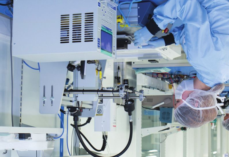
Abstract

Over the past 50 years, many different gyro technologies have been developed and used in space,
with Fiber Optical Gyros (FOG), Ring Laser Gyros (RLG) and Hemispherical Resonator Gyros
(HRG) being predominantly used from the late ‘90s up to today. Each technology offers a wide
range of advantages and disadvantages while most of the time offering a similar performance. More
recently, new applications have emerged in the commercial industry for which accuracy and
precision are no longer the driving factors. Instead, reliability, mass, power budgets, and meeting
performance at reduced cost and size have become paramount.

In that context, InnaLabs has developed a Coriolis Vibratory Gyroscope (CVG) sharing common
features with HRG, and, with the support of the European Space Agency, a 3-axis Rad-Hard Rate
Measurement Unit (RMU) named ARIETIS is now being developed by Innalabs to address Earth
Observation ap-plications in Low-Earth Orbit (LEO), Navigation in Medium-Earth Orbit (MEO), and
AOCS in Geostationary Orbit (GEO) with lifetime of more than 15 years. After a brief description of
the InnaLabs CVG basic principles and an overview of the CVG technical strengths in comparison
to competing for available technologies, this paper describes the key features and budgets of
ARIETIS, it’s design, construction and operating principles, with a special emphasis on the targeted
end-of-life performance.

                             41st Annual AAS Guidance & Control Conference
                                      Breckenridge, Colorado, USA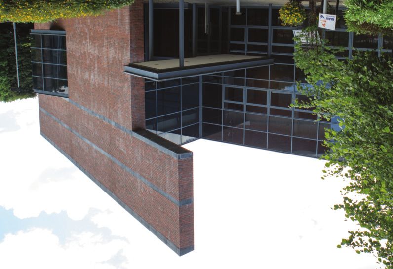
1.         InnaLabs space strategy

InnaLabs is a privately held Irish limited company located in Dublin (Ireland) which has developed
in the past six years, a portfolio of high-quality, innovative Coriolis Vibratory Gyroscopes (CVG) that
deliver market-leading performance to cost ratios.

With thousands of units already deployed across several Commercial and Defense industries in
Europe, InnaLabs CVG [1] [2] has become very attractive to the Space Industry due to its low-cost,
stabilisation performance of few °/hr, high reliability, long lifetime and specific cost to performance
ratio.

In perfect alignment with the Company’s vision to challenge
existing high-end gyros technol-ogies in all sectors, and with
Enterprise Ireland’s R&D support , the Company developed
a team of experts and industrialists implementing with drive
a Space strategy.

The achievement is clear. InnaLabs was awarded ISO
9001:2008 certification in 2014 and have been successfully
audited by major EU and US Space companies. In 2016,
                                                                              Figure 1. Innalabs Ltd, Dublin, Ireland.
twenty InnaLabs CVG were orbiting Earth on board of LEO
satellites into sun synchronous orbits for Earth Obser-vation
and more than 270,000 hours in space have passed so far
without any performance devia-tion. In December 2016,
InnaLabs won its first contract with the European Space
Agency (ESA) to develop ARIETIS, a 3-axis Rad-Hard Rate
Measurement Unit for the global commercial space market.
Very recently, in December 2017, ARIETIS Preliminary
Design Review (PDR) was successfully completed and
                                                                              Figure 2. Innalabs Ltd state of the art clean-room
passed, and the next phase of the development has now                         ISO Class 7 manufacturing line.
commenced with the delivery and qualification of an
Engineering Qualification Model (EQM) in the next 18
months and commercial products available in the year 2020.

*Chief Technology Officer, InnaLabs Ltd., Snugborough Road, Blanchardstown,

Ireland.
†
    AOCS/GNC Sensors & Actuators Coordinator, AOCS and Pointing Systems -

TEC-SAA, European Space Agency, ESTEC, Noordwijk, The Netherlands.
                                                                              Figure 3. ARIETIS 3-axis RMU
*www.enterprise-ireland.com

                                    41st Annual AAS Guidance & Control Conference
                                             Breckenridge, Colorado, USA
2.     Technology background

Since the ‘60s, many different gyro designs have been developed and customized to address the
needs of space satellites. This includes:

 - DTG: Two-axis dry tuned gyroscopes (developed in the ‘60s)
 - HRG: Hemispherical Resonator Gyroscope (developed in the ‘60s)
 - RLG: Ring Laser Gyroscopes (developed in the ‘70s)
 - FOG: Fibre Optic Gyroscopes (developed in the ‘70s)
 - MEMS CVG: Microelectromechanical systems, CVG based (developed in the 2000s)

However, with the development in the late ‘70s of digital electronics with increased signal processing
capabilities, in the ‘90s nearly all new applications on Land, at Sea, and in the Air, became
Strapdown. FOG, HRG and RLG were then predominantly used at the expense of spinning wheel
technologies (DTG), and that trend has continued to be emulated within the Space segment.

Today, about 1,000 operational satellites are in orbit, and with the development of the telecom
market and the requirements for global Internet broadband service to individual consumers,
thousands of satellites will have to be launched in the next few years in LEO and GEO. This requires
a step-change in the manufacture of satellites at a prime level to component suppliers to achieve
low-cost, less mass, less power consumption, and ultimately to scale up production.

In that context, Coriolis gyros (HRG and MEMS CVG) are particularly interesting as their mass and
size are significantly reduced, and, because the number of parts for these solid-state sensors is
much less than for other technologies, their MTBF is advantageously high and their production cost
is obviously low. For Land and Space applications, a broad categorization of gyro types and
associated MTBF levels is provided in the following Table:

                      Table 1. Broad categorisation of gyro types based on MTBF levels

                             41st Annual AAS Guidance & Control Conference
                                      Breckenridge, Colorado, USA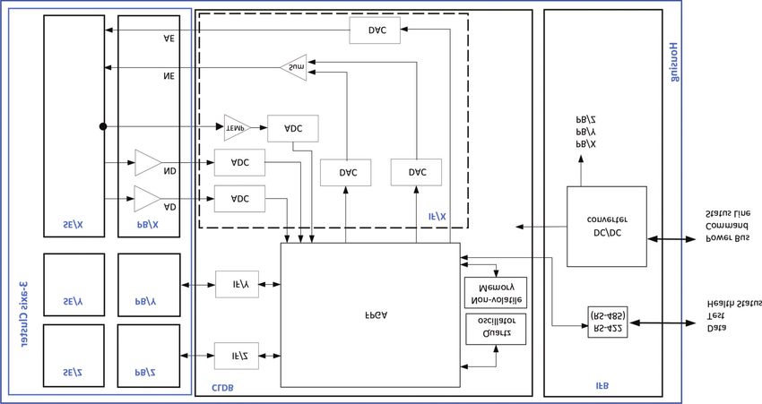
Presently, HRG Coriolis gyros [3] have become “sensors of choice” for high value satellites and
long space missions, as demonstrated in Europe with REGYS20 now qualified to Alphabus and
Spacebus 4000 geostationary communications platforms, and by the figures achieved by the
Northrop Grumman SIRUTM with Angle Random Walk (ARW) parameters well below 0.0002°/√hr,
more than 35 million on-orbit hours and 100% mission success.

However, these HRG solutions remain significantly expensive and therefore do not address well
the medium accuracy segment in LEO up to GEO which requires sensors delivering 1°/hr bias
stability over long observation periods and ARW of less than 0.01°/√hr. High-performance MEMS
Coriolis gyros could be suggested as alternatives for that specific segment, but no competitive
solution (price versus performance) has yet been successfully commercialised.

This middle point that was missing between HRG and MEMS Coriolis gyros thus laid the foundation
for building up InnaLabs CVG technology.

         Figure 4. InnaLabs CVG resonator                   Figure 5. HRG resonator

Figure 3. InnaLabs CVG resonator (left) – HRG resonator (right )

The basic principles of the Coriolis gyroscope technology are well known, as the first reported
practical demonstration was used in the Foucault pendulum to measure the earth’s rotation in 1851.
However, the conversion of the initial idea into practicality started in 1965 with the development of
the Hemispherical Resonator Gyros (HRG) by Delco (today Northrop Grumman). For those familiar
with HRG design, InnaLabs CVG and HRGs [3] [4] belong precisely to the same family and have
numerous features in common. The two designs host a 3D-axisymmetric resonator with a central
stem holding the resonator, and both have similar outline dimensions of few cubic centimetres in
volume. Both operate with one mode being excited to provide the linear momentum (primary mode),
and that mode is then coupled to a second mode (secondary mode) by Coriolis forces induced by
rotation of the structure around its axis of symmetry, referred to as the sensitive axis.

                                41st Annual AAS Guidance & Control Conference
                                         Breckenridge, Colorado, USA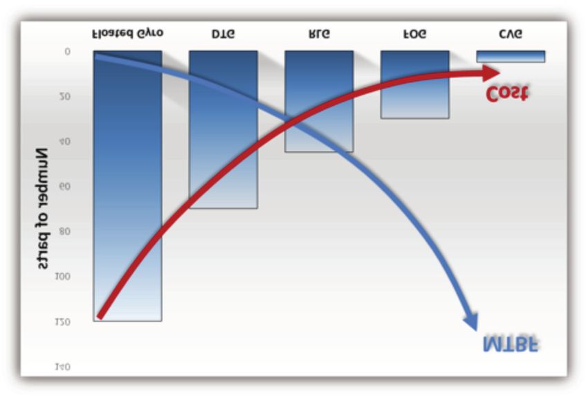
Still, from a cost perspective, considering overall materials involved, machining and assembly
processes, the InnaLabs CVG design exhibits key advantages leading to categorising that gyro-
scope as a “Low-Cost HRG” design.

 InnaLabs CVG                                         HRG
 Metal resonator                                      Silica resonator
 Cylindrical resonator                                Hemispherical resonator
 Piezo-electric pick-off and drive system             Electrostatic pick-off and drive system
 directly attached to the bottom flat surface         requiring high drive voltage and
 of the resonator (Figure 4)                          micrometric gap between electrodes
 Medium vacuum required in the cavity                 High vacuum assisted by getter material
 hosting the resonator                                in the cavity hosting the resonator
 ⇒ Low Cost                                           ⇒ High Cost

Table 2. Key design features of InnaLabs CVG

As a result, after having experienced in recent years a significant growth and successes in high-
end land stabilisation applications, InnaLabs CVG is now being considered by ESA in a custom
rad-hard 3-axis package named ARIETIS for LEO, MEO, and AOCS in Geostationary Orbits and
Science missions. That development started on January 30th, 2017 and, although the land qualified
InnaLabs CVG resonator is reused, it includes the development of a fully digital control loop system
and new assembly processes improving cost and performance. A PDR has been passed in
December 2017, and the project is now heading to an EQM delivery in 2019 to demonstrate
performance in PLATO ESA mission environment and lifetime. PLATO (Planetary Transits and
Oscillations of stars) is the third medium-class mission in ESA's Cosmic Vision programme and is
considered well representative of future ESA science missions.

                             41st Annual AAS Guidance & Control Conference
                                      Breckenridge, Colorado, USA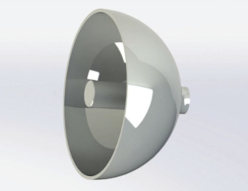
3.        ARIETIS key features

Regarding specifications, ARIETIS is a high-performance, high-reliability, ITAR-free non-
redundant 3-axis Gyros Unit providing inertial angle increments measurement of rotations
about three orthogonal axes. The output is provided on a non-redundant RS-422 data bus
with RS-485 compatibility. ARIETIS also comes with in-orbit calibration functionalities,
displays a non-redundant RS-422 stimuli interface and its power interface is compatible with
Spacecraft Primary power of 28 VDC nominal up to 100 VDC.

The mass of the equipment is targeting 2kg and its power consumption is below 7W. Its
measurement range is settable up to ±96°/s, with noise and ARW parameters optimised for
±3°/s. The estimated reliability figure of ARIETIS is less than 500 FIT at 30°C (MTBF of
2,000,000 hours) and the equipment is being designed for long life-time GEO missions of
more than 15 years with a solid sphere dose depth curve exhibiting TID of few hundreds of
kRad over the mission duration. The equipment will be qualified to a temperature range of
-40°C (-40°F) to +70°C (+158°F) and shall withstand random vibration profiles during launch
phase of 31.7 grms.

The following Table 3 provides an overview of the key functional performance of ARIETIS:

    Performance Parameters                                       Value
    Switch-on response time                                      ≤ 1s
    Time to full performance after switch-on                     ≤ 6s
                                                                 ≤ 0.005°/√hr (up to ±3°/s)
    ARW
                                                                 ≤ 0.16°/√hr (from 3 to ±96°/s)
    Bias stability over 24hr (steady temperature)                ≤ 1.5°/hr (1σ)
    Bias stability over 1hr (steady temperature)                 ≤ 0.3°/hr (1σ)
    Bias errors (all effects, EOL )                              ≤ 5°/hr (max)
    Scale Factor repeatability errors (all effects, EOL)         ≤ 700ppm (1σ)

Table 3. ARIETIS key features

2
    End Of Life

                                41st Annual AAS Guidance & Control Conference
                                         Breckenridge, Colorado, USA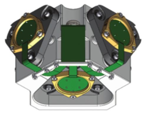
4.      ARIETIS architecture

The current embodiment of ARIETIS is composed of four main modules, a housing, a 3-axis cluster
hosting three InnaLabs CVG sensing elements (SE/X, SE/Y, SE/Z) and proximity boards (PB), and
a set of two electronics used to operate and perform all functions required by the equipment: CLDB
(gyro Digital Control Loops) and IFB (Interface Board). CLDB hosts a European new generation
rad-hard FPGA (65nm technology) which manages the gyro control loops and the communication
to the user. IFB includes a DC/DC converter and digital means to interface with the User on a
RS-422 serial output. Each CVG sensing element is attached to a vibration isolator to isolate them
from high-vibrations levels during the launch phase.

Figure 4. ARIETIS equipment (left), 3-axis CVG cluster (right)

The following block diagram provides more details on the architecture:

Figure 5. Block diagram

                                  41st Annual AAS Guidance & Control Conference
                                           Breckenridge, Colorado, USA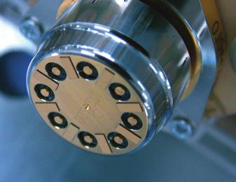
For each CVG sensing element (SE), 12-bits/1MHz ADC functions are used to digitise the primary
mode detection signals (AD), the secondary mode detection signals (ND) and each SE temperature
sensor signal (TEMP). The ADC functions include low-pass filtering and scaling functions.

As InnaLabs CVGs are operating closed loop in a Force Rebalance (FR) control system [5], once
digitised, AD, ND and TEMP are processed in the FPGA which implements the following functions:
a PLL, amplitude control of the primary mode, In-phase and In-quadrature control of the secondary
mode, compensation of errors, and health status monitoring. 12-bits/1MHz DACs are used to
feedback appropriately each control signal to each resonator, and an external non-volatile memory
is used to store the compensation parameters for correction of Bias, Scale Factor and misalignment
errors.

IFB hosts a DC/DC converter function interfacing the power bus of the satellite and providing to
ARIETIS sub-functions regulated DC secondary voltages. That DC/DC function is not a redundant
system but works as a dual power bus connector providing some of the redundancy benefits of a
dual DC/DC converter.

                            41st Annual AAS Guidance & Control Conference
                                     Breckenridge, Colorado, USA
5.      Preliminary results

Bias errors of InnaLabs CVG are mainly temperature dependent as temperature is a factor that
influences the physical properties of any mechanisms involved in energy loss. This leads to a
change of the damping level of the primary resonant mode, upsets the stability of the controlled
oscillation and leads to bias errors. As early as 2014 [2], few improvements have been imple-mented
to InnaLabs CVG control system to cope with that and achieve excellent performance parameters
and reduced ARW.

A typical bias temperature stability result on an InnaLabs’ 1-axis gyro is shown in Figure 6 below.
The analysis is based on the bias residuals calculated by subtracting a third order least squares
model from the raw data over the full temperature range. Pending completion of ARIETIS digital
development in the next 18 months, the test is carried out at breadboard level with InnaLabs’ current
qualified analogue control electronics using MIL grade components. The temperature range is -
45°C to +90°C, and the ramp rate is ±1°C/min:

Figure 6. Temperature profile at SE level (left) - Bias errors over time (right)

From this, between -40°C and +70°C, the bias peak value is ~1.94°/hr with a standard devia-tion
of 0.7°/hr. These bias thermal stability figures are significantly below the EOL specification of ±5°/hr
set in Table 3. When considering the gyro output noise and the gyro bias short-term sta-bility, the
Allan Variance method [6] can advantageously be used to highlight the different types of random
processes generating bias instabilities.

                                    41st Annual AAS Guidance & Control Conference
                                             Breckenridge, Colorado, USA
The figure below shows the results obtained. The minimum root Allan Variance is 0.015/hr at 30
seconds which is consistent with an estimated ARW of less than 0.0016/√hr. The straight red line
with slope -1/2 indicates the specification limit sets in Table 3. The origin of the slope -1 which can
be seen on left side of the data plots is described in [2] and is related to the electrical-thermal noise
generated by the op-amps scaling Node detection signals:
Figure 7. Allan deviation of InnaLabs CVG
Finally, to conclude this section on what is important to the survival of space equipment, radiation
levels of 170kRad (TID) over one month have been investigated at CVG Sensing Element (SE)
level. Gamma irradiations were performed with a panoramic Cobalt 60 source of 14.8 TBq providing
a dose rate of 210rad/hr. As expected, no significant bias radiation sensitivity has been observed
indicating that the InnaLabs CVG technology used in ARIETIS is inherently and naturally radiation
hardened.
41st Annual AAS Guidance & Control Conference
Breckenridge, Colorado, USA6. Conclusion
The design, construction and operating principles of InnaLabs ARIETIS 3-axis Rad-Hard Rate
Measurement Unit (RMU) have thus been described. This ITAR-free product is being developed
under a European Space Agency contract with an EQM fully qualified to long-life GEO and Science
missions in the next 18 months. Commercial products will be ready to fly from the year 2020.
ARIETIS is based on InnaLabs patented CVG technology which delivers already market-leading
performance to cost ratios for the past six years on land and marine stabilisation platforms. That
technology is a middle point, in some way, between HRG and high-performance MEMS Coriolis
gyros with bias in-run stability parameters of less than 0.02/hr and ARW better than 0.002/√hr.
Although InnaLabs is relatively new as a space company when compared to the overall
industry, our combination of rare inertial sensor experts, operational excellence, and world-
class engineering have positioned us as a vital source in an industry where space sensors
are a scarce resource. We are comfortable with the challenges posed by our clients and
industry partners and are in the process of delivering exciting space grade sensor
technology that will be a key milestone in the development of inertial sensors for space.
References
[1] J. Beitia, “High-grade CVG for Stabilisation Control Systems and Tactical Grade Systems”,
Proceedings of the Gyro Technology Symposium, Germany 2013.
[2] J. Beitia, “Low Cost CVG for High-grade North Finders and Targeting Systems”, Proceedings of the
Gyro Technology Symposium, Germany 2014.
[3] L. Rosellini, “REGYS 20: a promising HRG-based IMU for space application”, GNC 2008, 7th
International ESA Conference on Guidance, Navigation and Control Systems, June 2008, Tralee,
County Kerry, Ireland.
[4] D.M. Rozelle, The hemispherical resonator gyro: from wineglass to the planets. Proc.19th AAS/AIAA
Space Flight Mechanics Meeting, 2009, pp1157-1178Style Manual. New York 17, New York: American
Institute of Physics, 2nd ed., 1959.
[5] IEEE 1431-2004, Standard Specification Format Guide and Test Procedure for Coriolis Vibratory
Gyros.
[6] IEEE Std 647-1995, Standard Specification Format Guide and Test Procedure for Single-Axis Laser
Gyros.
InnaLabs® Ltd, Blanchardstown Industrial Park, Snugborough Road, Blanchardstown, D15, Ireland. T: +353 1 8096200 | W: www.innalabs.com
41st Annual AAS Guidance & Control Conference
Breckenridge, Colorado, USAYou can also read