Additive Manufacturing Redesigning of Metallic Parts for High Precision Machines - MDPI
←
→
Page content transcription
If your browser does not render page correctly, please read the page content below
Additive Manufacturing Redesigning of Metallic
Parts for High Precision Machines
Manuela Galati *, Flaviana Calignano, Marco Viccica and Luca Iuliano
Department of Management and Production Engineering (DIGEP) - Integrated Additive Manufacturing Center
(IAM) - Politecnico di Torino, Corso Duca Degli Abruzzi, 24 - 10129 Torino, Italy; flaviana.calignano@polito.it
(F.C.); marco.viccica@polito.it (M.V.); luca.iuliano@polito.it (L.I.)
* Correspondence: manuela.galati@polito.it; Tel.: +39 011 090.4569
1. Introduction
The design optimization has been performed using manually tool and topology optimization
(TO) techniques. TO is based on the use of the SIMP method (Solid Isotropic Material with
Penalisation). The SIMP method predicts an optimal material distribution within a given design
space, for given load cases and boundary conditions. Initially, the domain is then discretized into a
grid of finite elements called isotropic solid microstructures. Each element is either filled with
material for regions that require material or emptied of material for regions where you can remove
material (representing voids). The emptied regions are those ones with low energy deformation. The
distribution of energy deformation follows stress distribution. Where the stresses are low or equal to
zero there the material does not participate in the structural stiffness of the component and therefore
can be removed. The SIMP method is the most used among TO techniques and mainly works for
those components that show some areas with low stresses. On the other hand, when the stresses are
low everywhere in the component the SIMP method could not lead to convergence. For this reason,
the system that included the rails has been redesign manually only adopting the design for additive
manufacturing while a specific methodology was proposed for the bracket redesign. During the
optimization phase, a tetrahedral mesh has been used to speed up the simulation time.
2. Analysis of the Rails and Optimization
2.1. Load Condition:
The simulation included all components of the systems. The probe, and the vision and the
lighting systems were modelled as concentrated masses. The concentrated mass was placed in a point
positioned in the coordinate of the center of gravity of the simulated system. The concentrated mass
was then connected to the bracket by using a coupling constraint between the concentrate mass and
the surfaces that were coupled with the simulated systems. To simulate the magnetic adhesive force
between the magnets and the linear motor, vertical loads and longitudinal constraints were applied
on their respective surfaces. The bottom part of the Y-rail was fully constrained to simulate. The
contact between the surfaces of different components of the systems has been simulated as fully
coupled.
2.2. Original Component
Software for FE analysis: InspireTM 2018 SolidThinking®, version 2018, build 9508,
Type of mesh: tetrahedral
The maximum dimension of the element: 2 mm
Total number of elements: 1299903
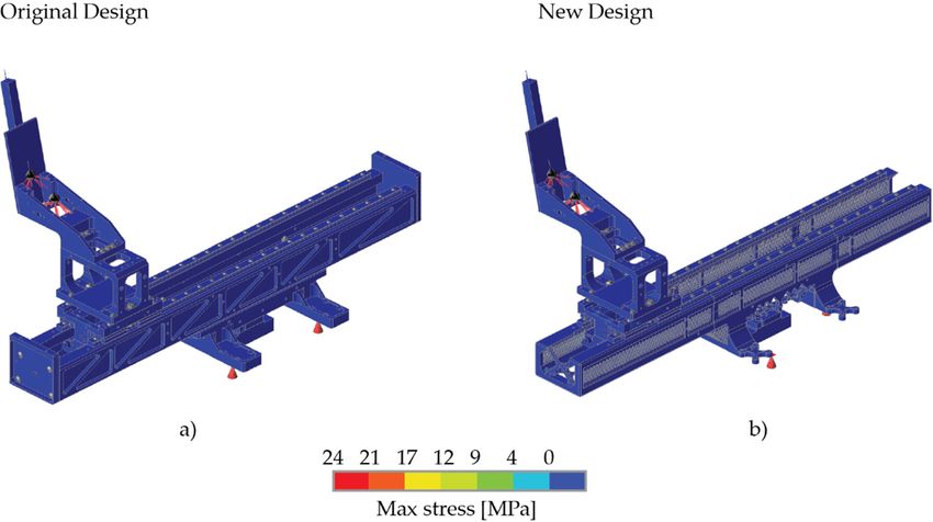
Figure S1 (a) shows the stress distribution on the system. The low stresses and great safety
coefficient /ratio between the maximum stress and yield stress of the material) respect to the yield
stress of the material (503 MPa) are due to the high stiffness requirements which were applied the
design stage. This stiffness must be preserved during the optimization to guarantee low deformation
Crystals 2020, 10, 161; doi:10.3390/cryst10030161 www.mdpi.com/journal/crystals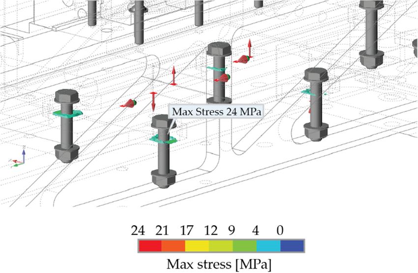
Crystals 2020, 10, 161                                                                                             2 of 4

and displacements during the working conditions of the system that do not affect the accuracy of the
machine.

2.3. Optimised Component
     Software for the redesign: Dassault Systemes SolidWorks® 2017. The entire system has been
considered as a single component and completely redesigned. To fit the production volume of most
common laser powder bed fusion (L-PBF) systems the component has been split into three parts and
a shaft-hub interference fit was designed (Figure S3).
     Software for FE analysis: InspireTM 2018 SolidThinking®, version 2018, build 9508,
     Type of mesh: tetrahedral
     The maximum dimension of the element: 2 mm
     Total number of elements: 901534
     Figure S1 (b) shows the performance of the new design under the identical load condition of the
original design. The stresses are low and great safety coefficient respect to the yield stress of the
material (350 MPa) is registered.
Software for the design of the job: Materialise Magics 22.0
Software for the design of fastening systems for the milling operations: Dassault Systemes
SolidWorks® 2017

      Figure S1. Comparison of the Von Mises stress between the original and the new design. As can be
      observed, the stress on both parts is extremely low. The maximum values around (24 MPa) is
      registered in the contact between the bolts the rails (Figure S2). The low stresses and great safety
      coefficient respect to the yield stress of the material (503 MPa for the Al7075 of the original design and
      350 MPs for the AlSi10Mg of the new design) are due to the high stiffness requirements which were
      applied the design stage (which means low deformation and displacements during the working
      conditions of the system).
Crystals 2020, 10, 161 3 of 4
Figure S2. Localisation of the only areas in which the maximum stress has been registered.
Figure S3. Design details of the shaft-hub interference. The features have been designed to guarantee
an adequate stiffness of the connection. This is ensured not only by the feature ‘dimensions but also
by the roughness of tilted surfaces that is slightly higher of the horizontal and vertical ones and helps
to improve the contact between the surface.
3. Analysis of the Bracket
3.1. Load Condition
The probe, and the vision and the lighting systems were modelled as concentrated masses. The
concentrated mass was placed in a point positioned in the coordinate of the center of gravity of the
simulated system. The concentrated mass was then connected to the bracket by using a coupling
constraint between the concentrate mass and the surfaces that were coupled with the simulated
systems. The four bolts were simulated by fully constrain the surfaces corresponding to the threaded
surfaces.
3.2. Original Component
Software for the analysis: Abaqus CAE 2017
Type of mesh: hexahedral
The maximum dimension of the element: 0.8 mm
Total number of elements: 81824
3.3. Optimised ComponentCrystals 2020, 10, 161 4 of 4
Software for the redesign: Visi 2018 in which the result of the topology optimization has been
directly modified
Software for FE analysis: Abaqus CAE 2017 and solved by Abaqus Standard
Type of mesh: hexahedral
The maximum dimension of the element: 0.8mm
Total number of elements: 116914
Software for the design of the job: Materialise Magics Version 21.1
© 2020 by the authors. Licensee MDPI, Basel, Switzerland. This article is an open access
article distributed under the terms and conditions of the Creative Commons Attribution
(CC BY) license (http://creativecommons.org/licenses/by/4.0/).You can also read