An Event Horizon Imager (EHI) Mission Concept Utilizing Medium Earth Orbit Sub-mm Interferometry - arXiv
←
→
Page content transcription
If your browser does not render page correctly, please read the page content below
0254-6124/2021/41(2)-211–23         Chin. J. Space Sci.

KUDRIASHOV V, MARTIN-NEIRA M, ROELOFS F, FALCKE H, BRINKERINK C, BARYSHEV A, HOGERHEIJDE M,
YOUNG A, POURSHAGHAGHI H, KLEIN-WOLT M, MOSCIBRODZKA M, DAVELAAR J, BARAT I, DUESMANN B,
VALENTA V, PERDIGUES ARMENGOL J M, DE WILDE D, MARTIN IGLESIAS P, ALAGHA N, VAN DER VORST M. An
Event Horizon Imager (EHI) mission concept utilizing medium Earth orbit sub-mm interferometry. Chin. J. Space Sci., 2021,
41(2): 211-233. DOI:10.11728/cjss2021.02.211

  An Event Horizon Imager (EHI) Mission Concept
Utilizing Medium Earth Orbit Sub-mm Interferometry∗
    KUDRIASHOV V1 MARTIN-NEIRA M2 ROELOFS F1 FALCKE H1,3
    BRINKERINK C1 BARYSHEV A4 HOGERHEIJDE M5,6 YOUNG A1
POURSHAGHAGHI H1 KLEIN-WOLT M1 MOSCIBRODZKA M1 DAVELAAR J1,7
  BARAT I2 DUESMANN B2 VALENTA V2 PERDIGUES ARMENGOL J M2
  DE WILDE D2 MARTIN IGLESIAS P2 ALAGHA N2 VAN DER VORST M2
 1(Department of Astrophysics/IMAPP, Radboud University Nijmegen, P.O. Box 9010, 6500 GL Nijmegen, the Netherlands)

                            2(ESTEC/ESA, Keplerlaan 1, 2201 AZ Noordwijk, the Netherlands)

           3(Max Planck Institute for Radio Astronomy, Auf dem Hügel 69, D-53121 Bonn (Endenich), Germany)

                      4(University of Groningen, Landleven 12, 9747 AD Groningen, the Netherlands)

                5(Leiden Observatory, Leiden University, PO Box 9513, 2300 RA, Leiden, the Netherlands)

                 6(Anton Pannekoek Institute for Astronomy, University of Amsterdam, Science Park 904,
                                        1098 XH, Amsterdam, the Netherlands)

        7(Center for Computational Astrophysics, Flatiron Institute, 162 Fifth Avenue, New York, NY 10010, USA)

    Abstract Submillimeter interferometry has the potential to image supermassive black holes on event horizon
    scales, providing tests of the theory of general relativity and increasing our understanding of black hole accretion
    processes. The Event Horizon Telescope (EHT) performs these observations from the ground, and its main
    imaging targets are Sagittarius A* in the Galactic Center and the black hole at the center of the M87 galaxy.
    However, the EHT is fundamentally limited in its performance by atmospheric effects and sparse terrestrial
    (u, v)-coverage (Fourier sampling of the image). The scientific interest in quantitative studies of the horizon
    size and shape of these black holes has motivated studies into using space interferometry which is free of these
    limitations. Angular resolution considerations and interstellar scattering effects push the desired observing
    frequency to bands above 500 GHz.
          This paper presents the requirements for meeting these science goals, describes the concept of interfero-
    metry from Polar or Equatorial Medium Earth Orbits (PECMEO) which we dub the Event Horizon Imager
    (EHI), and utilizes suitable space technology heritage. In this concept, two or three satellites orbit at slightly
    different orbital radii, resulting in a dense and uniform spiral-shaped (u, v)-coverage over time. The local
    oscillator signals are shared via an inter-satellite link, and the data streams are correlated on-board before
    final processing on the ground. Inter-satellite metrology and satellite positioning are extensively employed to
    facilitate the knowledge of the instrument position vector, and its time derivative. The European space her-
    itage usable for both the front ends and the antenna technology of such an instrument is investigated. Current
    and future sensors for the required inter-satellite metrology are listed. Intended performance estimates and

    ∗ The research work reported in the paper was partly supported by the Project NPI-552 “Space-to-space Interferometer
      System to Image the Event Horizon of the Super Massive Black Hole in the Center of Our Galaxy” co-funded by the
      European Space Agency (ESA) and the Radboud University of Nijmegen (ESA contract 4000122812), and by the NWO
      project PIPP “Breakthrough Technologies for Interferometry in Space”.
      Received August 20, 2020. Revised January 29, 2021
      E-mail: V.Kudriashov@astro.ru.nl. Corresponding author: Kudriashov V
212                                                              Chin. J. Space Sci.                    2021, 41(2)

      simulation results are given.
      Key words Instrumentation, Space, VLBI, Radio Telescopes
      Classified index V 476.9, TP 73

1 Introduction                                             timately – the Earth’s diameter) and are affected sig-
                                                           nificantly by propagation effects in the Earth’s atmo-
Studying the size and shape of a black hole                sphere (e.g. Ref. [17]). Signal attenuation and phase
“shadow” [1] is considered to be one of the crucial ex-    turbulence introduced primarily by water vapor in the
perimental tests of General Relativity[2−4] . The Su-      troposphere make VLBI observations at wavelengths
permassive Black Hole (SMBH) in the center of our          significantly shorter than ∼0.8 mm feasible from just
Galaxy, with the associated radio source Sgr A*, has       a few extremely dry sites on Earth (such as the Cha-
a mass M of 3.964±0.047stat ±0.0264sys ×106 M and          jnantor Plateau in Chile, Mauna Kea in Hawaii, and
is located at a distance D of 7946 ± 50stat ± 32sys pc     the South Pole), if the weather conditions are favor-
from Earth[5]. The GRAVITY Collaboration[6] mea-           able.
sure a distance of 8178 ± 13stat ± 22sys pc. Assuming            Both of these limitations, the maximum baseline
a Schwarzschild (non-spinning) black hole, the expec-      length and the limited availability of ground-based
                      √
ted shadow size is 2 27GM/c2 D = 51 µas, where G           stations at high frequencies, can be overcome by pla-
is Newton’s gravitational constant and c is the speed      cing all sub-millimeter VLBI telescopes in space. An
of light. This expected angular size is the largest        additional advantage of such an approach is the possi-
of all black holes in the sky[7]. The shadow of the        bility of obtaining better (u, v)-coverage when using
black hole in the nucleus of the active radio galaxy       an array of telescopes on freely flying satellites in-
Messier 87 (M87*) has been imaged with the Event           stead of an Earth-based array rotating as a solid body.
Horizon Telescope (EHT) as an asymmetric ring[8,9] .       Also, a dedicated fully space-based array will not be
Model fitting led to an angular size of one gravita-        constrained by the need to apply for limited observing
tional radius GM/c2 D of 3.8 ± 0.4 µas[10,11] , leading    time at facilities that are in high demand for many
to a Schwarzschild shadow size of 39 ± 4 µas. The          other science cases. On the other hand, if the weather
effect of the black hole spin on the angular size of the    conditions are favorable during the permitted obse-
shadow is      4%[12−14] . In addition to fundamental      rvation time, space-ground baselines could make use
physics, such observations promise a rich harvest for      of the high sensitivity of ground stations like ALMA,
astrophysical studies.                                     and fill the (u, v)-plane on short (hourly) timescales.
      The angular resolution required for decisive         A space-space system observing together with ground
observations of the SMBH shadow in these objects           stations when they are available could therefore be
is thus at the level of 20 µas or sharper. This reso-      considered.
lution can be achieved only by the technique of Very             To date, three successful demonstrations of
Long Baseline Interferometry (VLBI).                       (partial) Space VLBI (SVLBI) systems have been
      For the longest baselines available on the surface   achieved: TDRSS (1986–88), VSOP/HALCA (1997–
of Earth, the observations reaching the required angu-     2003) and RadioAstron (2011–2019) — see Ref. [18]
lar resolution must be conducted at short millimeter       and references therein. In all three cases, only one ele-
and sub-millimeter wavelengths. The results of obser-      ment of the SVLBI system operated in orbit. About a
ving M87* at 230 GHz (1.3 mm) with the EHT have            dozen other SVLBI studies considered various mission
been published recently[8−11,15,16] . The EHT has          concepts, some of them with two or more space-borne
demonstrated an angular resolution of about 20 µas in      elements, e.g., iARISE[19] and the Chinese SVLBI
the image of M87*. It is expected that, after ongoing      initiative[20,21] . All three already implemented sys-
expansions and upgrades, the EHT will also operate         tems and multiple design studies of SVLBI concepts
at 345 GHz (0.87 mm). EHT images are limited in            create a technological basis for prospective multi-
angular resolution by achievable baseline lengths (ul-     element sub-mm SVLBI systems.
Kudriashov V et al.: An Event EHI Mission Concept Utilizing Medium Earth Orbit Sub-mm Interferometry           213

      Another important technological contribution         its strong gravity, causing the appearance of a black
for prospective sub-mm SVLBI comes from develop-           hole “shadow”[1]. Due to the large angular sizes of
ments of microwave systems for astrophysical stu-          Sgr A* and M87*, they are the most attractive tar-
dies such as in COBE[22] , WMAP [23] , Planck[24], and     gets for imaging a black hole shadow.
Herschel[25], and in Earth observation missions such             The Event Horizon Telescope (EHT) imaged the
as SMOS[26] . The latter is of special interest as an      shadow of the black hole in the nucleus of the ac-
example of an aperture synthesis system in space.          tive radio galaxy Messier 87, M87*, as an asymmetric
      A prospective sub-mm SVLBI system for stud-          ring[8,9] , and a model fitting led to a Schwarzschild
ying SMBH shadows requires state-of-the-art space-         shadow size of 39±4 µas[10,11] . The EHT aims to
qualified technologies and technology developments.         image also the SMBH shadow of the Sgr A*. This
These include precise baseline state vector determi-       ground-based VLBI at the frequency of 230 GHz with
nation, flight dynamics and altitude determination[27]      an angular resolution of ∼25 µas allows to investigate
(addresses all 3), high-rate data exchange between         directly the manifestation of general relativity effects
space-borne SVLBI elements as well as between them         in the immediate vicinity of a SMBH and to con-
and an Earth-based data processing center[28,29] , and     strain models of the plasma flow around the black
ultra-fine synchronization of SVLBI elements. Some          hole[2,31,32] .
of the required technologies can rely on the exis-               A next step in studying the SMBH shadow ef-
ting developments in other applications, e.g. Ref. [28].   fect is distinguishing between geometries predicted
State-of-the-art technologies for the main reflector[24],   by different theories of gravity. Based on images by
and sub-mm receivers[25] are promising. The 4 m            Mizuno et al.[3] and Olivares et al.[33] comparing the
main reflector is bigger than in the ESA Planck. This       size and shape of the black hole shadow, we estimate
is bigger than the 3.5 m in the ESA Herschel too. The      that an angular resolution better than ∼5 µas could
single sideband (SSB) noise temperature aimed for in       potentially allow distinguishing between a Kerr black
this paper is smaller than in the ESA Herschel HiFi        hole and a dilaton black hole, and between a black
instrument.                                                hole and a boson star. It should be noted, however,
      In this paper, we present the science goals and      that this number was estimated based on two speci-
a concept of a multi-element sub-millimeter SVLBI          fic cases and may not hold under all circumstances.
system, provisionally called Event Horizon Imager          Another motivation for pushing towards a resolution
(EHI), formed by satellites on near-circular polar         of ∼5 µas is that parameters like the black hole spin
medium Earth orbits[30] . We assess the best feasi-        may become measurable. The black hole spin not on-
ble performance of the key elements of the science         ly affects the size and shape of the black hole shadow
instrument and supporting sub-systems in view of           (at a level of     4%, see the previous section), but
the latter’s correspondence to the best characteristics    it also affects the orbits of the surrounding plasma,
achieved to date in other space-borne applications.        causing its appearance and dynamics to change. Van
We also simulate reconstructed images of the main          der Gucht[34] have assessed the possibility to recover
science sources with the EHI.                              black hole spin from theoretical source models using a
                                                           machine learning approach. While the spin could not
2 Science Objectives                                       be recovered if the models were blurred to the EHT
                                                           resolution (∼25 µas), the correct spin was recovered
2.1 Imaging Black Holes Sgr A* and M87*                    from a range of five possible values in > 80% of the
At sufficiently high frequencies (∼ a few 100 GHz),          simulations of they were blurred to a resolution of
the emission from the accretion flow is mostly opti-        5 µas.
cally thin and allows us to probe its geometry down to           The EHI will test general relativity in a different
the smallest radii around the black hole. Theoretical      regime than, e.g., LIGO or VIRGO, which observe
simulations predict that this emission from the inner-     gravitational waves from merging black holes of tens
most accretion flow is bent around the black hole by        of solar masses, and also from other objects like neu-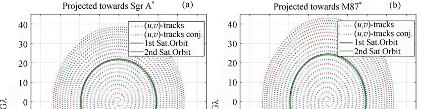
214                                                                Chin. J. Space Sci.                     2021, 41(2)

tron stars. The EHI aims to observe supermassive            (Table 1). As a secondary science case, the EHI will
black holes of millions to billions of solar masses.        provide valuable information on the emission from the
      Assuming a telescope with an Earth-size aper-         jets of other AGN (non-horizon) with unprecedented
ture (the limit for Earth-bound VLBI such as EHT),          resolution in a hitherto unexplored frequency regime.
the angular resolution of 5 µas requires an observing       2.2 Simulated Sub-millimeter Emission
frequency above 1 THz. Terahertz-band interferome-                 from Sgr A* and M87*
try on Earth-Earth baselines is challenging due to          In order to assess the required EHI system specifica-
the strong atmospheric turbulence and absorption.           tion, we simulate its imaging performance in obser-
Achieving the 5 µas resolution from a low Earth or-         vations of the prime target sources. The Spectral
bit requires an observation frequency above 0.8 THz,        Energy Distribution (SED) of emission from Sgr A*
which poses ambitious requirements to the interfer-         has a sub-mm peak[37] , while SED of M87* emission
ometer coherence (Eq. (1) in Ref. [35]). At least three     peaks at ∼100 GHz and slowly drops towards higher
GNSS satellites should be visible from the EHI satel-       frequencies[38] .
lites to perform the accurate (carrier phase relative)            Out of the two primary targets, Sgr A* consti-
navigation measurements. This limits the highest-           tutes a more challenging case because of significantly
possible altitude to ∼ 7500 km, at the initial GNSS vi-     more pronounced interstellar scattering effects as the
sibility simulation[36]; the dedicated MEO navigation       line of sight lies in the Galactic plane. For the purpose
study[28] might refine this altitude and the number of       of these simulations, we use as input a source bright-
GNSS transmitters in the common visibility of 2 na-         ness distribution consistent with a physical model of
vigation receivers by analysis of other navigation con-     the direct SMBH environment[39,40] .
stellations (apart from GPS-only in Ref. [36]). Medi-             As a benchmark observing frequency, we choose
um Earth orbits mitigate the observation frequency          690 GHz following considerations on demonstrated
requirement to about 500 GHz because of the base-           capabilities of space hardware[24]. We use four Ge-
lines involved at altitude ∼ 7500 km. At 500 GHz, in-       neral Relativistic Magnetohydrodynamics (GRMHD)
volving ground-based stations is challenging because        model images of the accretion flow around Sgr A* as
of strong absorption, scintillation and scattering in       input for our simulated observations. These are the
the atmosphere. Space-space interferometry is not           GRMHD models 16, 24, 31, and 39 from Ref. [39],
affected by these atmosphere-related issues, but it          ray-traced at 690 GHz. The models are considered to
poses many engineering challenges.                          be plausible representations of the source structure of
      An angular resolution of ∼5 µas should be suffi-        Sgr A* that fit the existing observational constraints.
cient to image SMBH shadows in several other sources        They represent physically different situations where
in addition to the prime candidates Sgr A* and M87*         the emission is dominated by an accretion disk (mo-

        Table 1 Horizon sizes and 230 GHz flux densities for several supermassive black holes
              which could be candidates for horizon-scale imaging with the EHI concept

                           Shadow               230 GHz flux              R.A. to                 Dec. to
         Source
                           size/µas              density/Jy               α/(◦ )                  α/(◦ )
         Sgr A*               53                     2.4                  39.36                    29
         M87*                42±3                    0.9                  39.36                   12.39
                                                                                 ∗∗
        IC 1459               9.2                   0.26                 27.23                    36.46
          M84                 9.1                   0.13                  40.8                    12.89
         M104                 5.7                   0.25                  37.06                   11.62
        IC 4296               2.5                   0.16                  22.90                   33.97
        Note Values are from Ref. [7, 8]. The axis α is normal to the EHI plane (Figure 4, Subsection 3.2),
        and the angle with ∗∗ requires a 180◦ turn of the EHI dishes with respect to the EHI plane.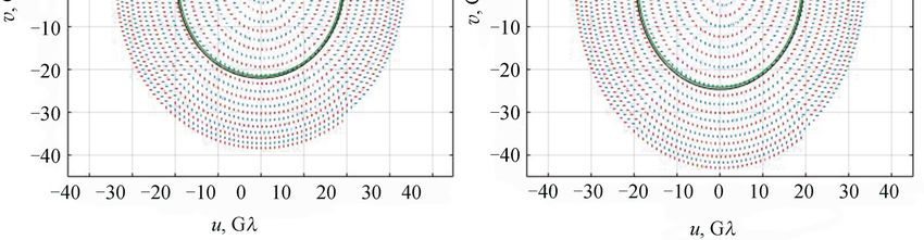
Kudriashov V et al.: An Event EHI Mission Concept Utilizing Medium Earth Orbit Sub-mm Interferometry 215
dels 16 and 31) or jet (models 24 and 39). They al- A frequency of 557 GHz was chosen here to align with
so consider different angles between the black hole the possible secondary science goal of imaging water
spin axis and the line of sight (60◦ for models 16 in protoplanetary disks[47] . The EHI orbit radii are
and 24, and 30◦ for models 31 and 39). The models flexible and can be temporarily set to a shorter sep-
range from 1.1 to 4.1 Jy in total flux density. Collec- aration in order to image these disks on arcsecond
tively, these models sample the solution space within scales. This secondary science goal is to be explored
the boundaries set by our current knowledge of the in more detail in future studies. Due to the flat con-
source. tinuum spectrum of M 87*, the source morphology is
Interstellar scattering adds spurious refractive expected to be similar at 557 and 690 GHz.
substructure to the observed image of Sgr A*[41−43] . 2.3 Variability of the Morphology of Sgr A*
This substructure is variable on timescales of about a and M87* as a Function of Time
day at 230 GHz and a few hours at 690 GHz. Over Sgr A* is variable on a timescale of minutes, which
time, the average effect of scattering is a blurring is much shorter than the time it will take to collect
of the source image by a scattering kernel that de- sufficient (u, v)-coverage for imaging. It has been
creases in size with observing frequency. Simula- shown[46,48] that making use of the linearity of the
ted time-averaged images at 230 and 690 GHz, inclu- Fourier Transform, visibilities in the same (u, v)-cells
ding the blurring effect from a Gaussian scattering obtained during different epochs with the EHT or
kernel[44], are shown in Figure 1 for model 39. The EHI may be averaged to obtain an image of the aver-
extrapolated major axis of the scattering kernel (see age source structure, clearly showing the photon ring.
1.309±0.015 mas·cm−2 in Ref. [45]) at 690 GHz is only The photon ring is a persistent feature that is unaf-
2 µas[46] , which is several times smaller than the max- fected by temporal variations in source morphology,
imum angular resolution that can be obtained with instead it is completely determined by the lensing of
the investigated setup. light in the strong gravitational field close to the black
Additionally, we use the time-averaged M87* hole.
model from Ref. [40], which includes accelerated elec- EHI observations of a variable source have been
trons to simulate emission from the relativistic jet. simulated[46] using a running GRMHD movie[41] . This
Electrons in the highly magnetized jet region are not movie was looped every five hours and scattered with
expected to be in thermal equilibrium but are acce- a moving scattering screen[42] . It was found that using
lerated by, e.g., magnetic reconnection events. The complex visibilities the reconstructed images appro-
ray-traced model image is shown in Figure 2. The ached the average source structure, but the recon-
image was not scattered since interstellar scattering structions deteriorate if one needs to rely on the bi-
is considered to be negligible in the direction of M87*. spectrum as the linearity does not hold for triple pro-
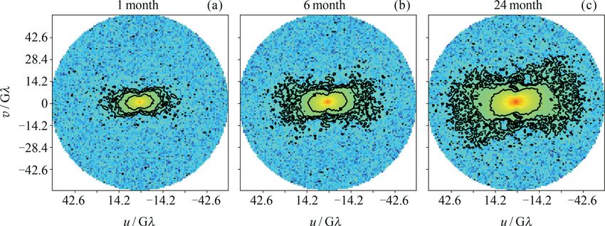
Fig. 1 Time-averaged simulated images of Sgr A* in the presence of interstellar scattering[39,45] . The 690 GHz image
in the right panel offers the opportunity to characterize the shadow geometry down to an angular scale of ∼5 µas,
while the left image does not due to the lower instrumental resolution and the presence of interstellar scattering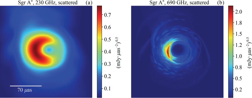
216                                                               Chin. J. Space Sci.                   2021, 41(2)

                                                            the ones on Earth, in particular at the lowest fre-
                                                            quency bands where atmospheric effects can still be
                                                            handled. The technical challenges to realize the hy-
                                                            brid system involve achieving coherent operation a-
                                                            mong all telescopes and data transfer to Earth, which
                                                            would lead to the use of optical links. Considering
                                                            radio regulations[52], a wide-enough frequency alloca-
                                                            tion band to downlink a radio-telescope’s electrical
                                                            field data (IF), which is of the order of tens/ hun-
                                                            dreds Gbit·s−1 , does not exist, and hence an optical
                                                            link would be required. Using a hybrid system like
                                                            this could provide the possibility of creating moving
                                                            images of a black hole[53], and one might be able to
Fig. 2 Time-averaged M87* model[40] at 557 GHz. This        observe even more and also weaker sources.
 frequency was chosen to align with the frequency of a            The EHI concept is focused around multiple
water line detected in protoplanetary disks[47] . Imaging   satellites, ideally launched together in a single launch
 water in protoplanetary disks might be considered as a     vehicle, operating from circular Medium Earth Or-
   secondary science goal for the EHI. Due to the flat
                                                            bits (MEOs) at slightly different orbital radii. The
continuum spectrum of M 87*, the source morphology is
                                                            differential drift of the satellites with respect to each
    expected to be similar over the range from 500 to
                                                            other yields a wide range of sampled baseline lengths
          690 GHz, with its features dominated
                by optically thin emission                  and orientations, while the orbital plane can be cho-
                                                            sen such that the chosen sources can all be studied
ducts of visibilities. For M87*, the variability time-      with optimal (u, v)-coverage.
scale is about 1500 times longer. Research is on-going            This section addresses the fundamental require-
to see if the expected variability of M87* is slow eno-     ments pertaining to different aspects of EHI system
ugh to allow a snapshot capability for EHI depend-          architecture.
ing on the distance between the satellite orbits, which     3.2 Orbit Requirements
gives a trade-off between the completion time of one         The angular resolution requirement for EHI (∼5 µas)
spiral iteration and the density of the (u, v)-coverage     can in principle be met by choosing an observing
(see Sections 3.2 and 4).                                   frequency close to 500 GHz and an orbital radius of
                                                            ∼14 000 km. This choice of frequency, in combination
3 System Concept and Technical                              with this orbit size, provides the additional advantage
  Requirements                                              that the system is not limited in its angular resolu-
                                                            tion by interstellar scattering effects towards Sgr A*.
3.1 Concept Overview                                        The specific choice of orbital radius is further con-
As discussed in Section 2, moving beyond the limits         strained by the presence of the Van Allen radiation
on resolution imposed by Earth-bound VLBI requires          belts, which limit the viable orbital radii to the re-
placing an interferometric instrument in orbit. The         gion between ∼12 000 and ∼19 000 km, and the need
aimed multi-frequency configuration of the EHI[49,50]        for GNSS positioning information. For successful cor-
includes an observing band above 500 GHz as well            relation, adequate knowledge of the baseline state ve-
as two lower bands (which have been preliminari-            ctor and its time derivative will be important. The re-
ly chosen to be at 230 GHz for comparison to EHT            quired availability of GNSS limits the maximum orbi-
and at 43 GHz to map jets, see Figure 6 in Ref. [51]).      tal radius for EHI satellites to be inside the outer Van
The starting idea is that EHI satellites will initial-      Allen belt (which spans orbital radii from 19 000 km
ly function independently of the EHT telescopes, but        to 26 000 km).
consideration is also being given to a hybrid system,             Precise relative positioning in MEO using GNSS
where the orbiting telescopes would be combined with        is a subject that has been only modestly explored so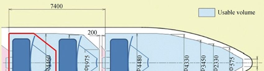
Kudriashov V et al.: An Event EHI Mission Concept Utilizing Medium Earth Orbit Sub-mm Interferometry                     217

far[54,55] . The expected real-time positioning accura-         ISP (the ESA Programme for Positioning Navigation
cy for MEO is below 5 cm in position and 1 cm·s−1               and Timing), will allow us to refine our estimate for
in velocity[56] . This is not yet at the required level         the accuracy of the achievable baseline state vector
for EHI, which needs a-posteriori (at image recon-              reconstruction.
struction i.e. the final) baseline vector knowledge to                We consider circular orbits to offer the most de-
a fraction of the observing wavelength ( 0.1 mm for             sirable geometry, as they will provide the most homo-
500 GHz, see Ref. [36]). The sub-wavelength precision           geneous (u, v)-coverage (see Figure 3). Furthermore,
might be obtained as a bonus end-product of interfer-           choosing an elliptical orbit[21] with an apogee closer
ometric observations (from VLBI correlator) though              to the GNSS shell will lower the quality of positioning
the signal to noise ratio isn’t enough for a detection.         information available for that segment of the orbit[56]
In order to achieve high-accuracy knowledge of both             or even eliminate GNSS coverage there entirely. The
the baseline vector (the vector connecting the phase            ongoing study of the precise relative positioning in
centers of the different telescopes in 3-D spatial coor-         MEO will valuate these reasons for the selection of
dinates) and its time derivatives, GNSS positioning             orbit radii and orientation.
measurements will need to be augmented with high                     Regarding our choice for the orbital plane of
precision optical metrology applied to EHI scales[57],          the satellites, we aim for an orientation that offers
or range-rate measurements over radio ISLs[36] . The            good and persistent visibility of our two main science
ongoing investigation[36] into precise relative positio-        sources, Sgr A* and M87*. These sources are each lo
ning in MEO to support science missions within NAV-             cated within ∼30◦ from the celestial equator, making

   Fig. 3 Both the (u, v)-coverage and the orbits of two EHI satellites are projected towards Sgr A* and M87* in the
left and right plots, respectively; the coverage with three satellites see Figure 1 in Ref. [46]. Because the satellites have
 slightly different orbital radii, their orbital periods are different, and their mutual separation (baseline) changes over
  time in both length and direction. This yields a spiral pattern in the (u, v)-plane. The maximum orbital altitude is
∼7500 km above the Earth’s surface, which is the limit resulting from the initial GNSS visibility study. The difference
in altitudes providing a spiral completion time of 1 month is 20 km, while in these figures the orbit altitude separation
is 300 km to allow clearer visibility of the separate loops. The spiral opening starts when the inter-satellite distance is
 equal to their altitude difference. The spiral progresses further outwards until the inter-satellite link gets blocked by
    Earth’s atmosphere, which here is considered to reach up to an altitude of about 100 km (the maximum central
                               √
  inter-satellite angle is ∼π/ 2 rad.) Swapping the orbit altitudes allows changing from spiral opening to closing and
vice versa. EHI calibration and commissioning benefit from swapping to the same altitudes, allowing for orbiting with
  a constant short baseline suitable for the highest correlated source flux density. These altitudes allow achieving the
     aimed angular resolution at 543 GHz, which is used in this figure. The consequences of adding a third satellite
                           for purpose of forming closure phases are currently being investigated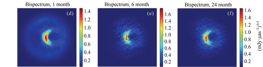
218                                                                  Chin. J. Space Sci.                     2021, 41(2)

high-inclination orbits the best choice for maximi-
zing the extent of our (u, v)-coverage for either
source. Simulations of ESA’s Earth Observation mis-
sions suggested that the polar orbits can be known
accurately[58,59] . The altitude increase (from LEO to
MEO) mitigates the atmospheric drag for benefit of
the relative navigation knowledge. The polar orbital
plane maintains its orientation for the benefit of the
main science goal (imaging major Sgr A*, M87* takes
months) and a satellite on this inertial plane may
maintain its orientation too. Furthermore, a polar
circular MEO allows flexible orbit altitudes. When               Fig. 4 EHI orbital plane as seen from the north pole.
the inter-satellite link is blocked by the Earth (and             At this plane, the Right Ascension (u, v)-coverage
the baseline is at its maximum), the orbits should be         projection narrowing (23%) is the same for both primary
                                                               targets (Figure 3). The loss in projected baseline length
reversed to make the baseline shrink again. For an
                                                               in Declination is limited to 13% towards Sgr A*, and is
orbit altitudes separation of 3 km, such a maneuver
                                                                 negligible (2%) towards M87*. Baseline length losses
can be done once every six months; such latency of 1
                                                              towards other science sources (smaller than 10 µas in size
maneuver per 6 months is cheap and hence, preferred
                                                               in Table 1) occur because of this geometrical projection
at a cost-effective mission.                                     as well. A rotating this orbital plane ∼3.8◦ to (140.9◦ ,
     For this reason, the polar orbital plane has been         0◦ ) enables to equalize the aperture projection towards
selected. The plane exhibits negligible precession and                    both Sgr A* and M87 in future work
in this way, it is keeping its orientation, relative to the
target sources, as stable as possible throughout the          The dwell time per grid cell is shortest for the longest
entire period of (u, v)-coverage accumulation, provi-         baselines. Following Eq. (2) of Ref. [46], the expres-
ding a stable evolution of (u, v)-coverage with time.         sion that gives the maximum integration time before
Our choice of orbital plane is depicted in Figure 4.          (u, v)-smearing becomes an issue is given by
However, the ongoing research also considers the case
                                                                                             P
of two orbits that are slightly slanted for the purpose                          tint <              ,               (1)
                                                                                          2πbθsource
of enhancing the relative navigation knowledge by us-
ing optical metrology in the out-of plane direction.          where tint is the maximum integration time, P is the
3.3 Time of Baseline Presence in                              orbital period of the satellites (and the cadence with
       (u, v)-grid Cell                                       which the (u, v)-vector circles the (u, v)-plane once),
When we consider the way in which visibility mea-             b is the baseline length expressed in observing wave-
surements need to be gridded in the Fourier plane             lengths (hence, dimensionless) and θsource is the an-
before their inverse transformation into the source           gular size of the source on the sky in radians. For a
image, we see that the choice of grid spacing is dic-         maximum baseline length of 50 Gλ, a source size of
tated by the overall angular size of the source on the        150 µas and an orbital period of 4.5 hours we get a
sky – coarser gridding limits source image reconstruc-        maximum integration time of 71 seconds if we wish
tion to a smaller field of view. Connecting this to the        to avoid (u, v)-smearing. This number scales inverse-
way in which (u, v)-coverage is built up for EHI (see         ly proportional to baseline length, allowing for longer
Figure 3), this means that limited time is spent in           time on shorter baselines. Namely, baseline lengths
each (u, v) grid cell per time the (u, v)-vector pas-         of an Earth diameter, 20 km, and 3 km allow a maxi-
ses through that cell. This imposes an upper limit on         mum integration time of 3 minutes, 1 day, and 1 week,
integration time from the need to avoid combining             respectively.
visibilities from different (u, v)-cells into a single mea-          We assume that integration is constrained addi-
surement, and it is an effect called (u, v)-smearing.          tionally 7.5 min by (u, v)-arc length 10◦ , at these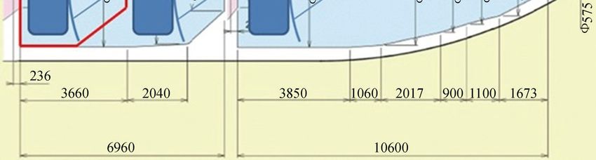
Kudriashov V et al.: An Event EHI Mission Concept Utilizing Medium Earth Orbit Sub-mm Interferometry            219

orbit radii.                                               such a mode is two spiral periods (2×29 days). An-
      An orbit radii difference of 20 km is used in this    other approach is to wait from the moment when the
paper (Figure 3). However, the EHI concept allows          inter-satellite links get blocked by the Earth until the
for manoeuvres between different orbital radii. A           inner satellite catches up with the outer satellite and
smaller difference could be useful for large-scale imag-    the inter-satellite link is not blocked anymore.
ing of, e.g., protoplanetary disks (Subsection 2.2). A          A coherence timescale (Case 3) shorter than the
larger difference (e.g. hundreds of kilometers) would       observation cycle (29 days) but still longer than the
decrease the time it takes to complete a (u, v)-spiral     detection time (limited by the (u, v)-grid cell cross-
up to the longest available baselines, which allows        ing time, see Subsection 3.3) would require having a
for faster imaging with the trade-off of sparser (u, v)-    significant SNR within a single (u, v)-grid cell cross-
coverage.                                                  ing time, because this cell noise can not be averaged
3.4 Imaging Approaches with Respect                        out anymore by multiple observation cycles. Also,
       to Instrument Phase Stability Timescale             there will be phase corruption between visibilities in
The type of imaging that is possible with the EHI          different (u, v)-cells.
depends on the system characteristics, most notably             These phase offsets should either be calibrated
the coherence time scale.                                  (which is challenging due to the lack of unresolved
      A phase-stable interferometer (Case 1) can in-       sources that could be used for phase referencing at
tegrate during years (infinite instrument coherence         these high frequencies and long baselines), or a third
timescale, the perfect knowledge of instrument posi-       satellite should be added to the system so that closure
tions). The correlator integration time, in this case,     phases[60] can be used for imaging.
is limited to (u, v)-grid cell crossing time Eq. (1) but        Closure phase is the phase of the triple product
this provides no obstacle because images can be re-        of visibilities on a triangle of baselines (bispectrum).
constructed by taking an inverse Fourier transform;        Closure phases are immune to most station-based
there is no requirement to achieve any particular SNR      phase errors as long as the instrument coherence time
within a (u, v)-grid cell crossing time (Subsecion 3.3).   allows the detection, or as long as the relative posi-
To provide the desired dynamic range, (u, v)-grid cells    tioning information allows imaging without the detec-
can be coherently averaged between numerous obser-         tion stage. Hence, the closure phase information can
vation cycles (29 days each for an orbit separation of     be used for image reconstruction without imposing
21 km).                                                    the technologically challenging requirement (Subsec-
      The next considered coherence timescale (Case        tion 3.5) of a system maintaining phase coherence on
2) is one observation cycle. The instrumental phase,       longer timescales. Closure phases between different
with contributions from the local oscillators, can be      triangles are robust even if the individual visibility
described in a delay and delay-rate (DnDR) model.          phases fluctuate. For these reasons, a three-satellite
The delay is the time difference of arrival of the sci-     system is seriously considered for the EHI concept.
ence signal to the interferometer, and the delay-rate           Finally, for a coherence time shorter than the
is its first time derivative. The instrumental phase        (u, v)-grid cell crossing time (Case 4), the detection
can be measured using a calibration observation with       should be done within this coherence time. Phase
the satellites orbiting on the same altitudes with a       corruption will appear between visibilities in different
short baseline between them. The baseline will have        (u, v)-cells, similarly as in the former case above.
a constant length and varying orientation, measuring       3.5 On Ultra-stable Oscillators
the total correlated source flux density.                   For sub-mm interferometry, frequency stability is of
      The derived DnDR can be fit for each observa-         paramount importance to preserve phase coherence
tion cycle. As a result, (u, v)-grid cells can be coher-   between the signals recorded at different stations
ently averaged between numerous calibrated observa-        right up to the stage of correlation. In VLBI, each sta-
tion cycles. Reversing the orbit altitudes allows clos-    tion has its own (ultra-stable) oscillator, and the vari-
ing the spiral back to the shortest baseline (Figure 3)    ous Local Oscillators (LOs) are regularly disciplined
and hence, the required phase stability time scale for     using a lower-cadence shared signal. For instance,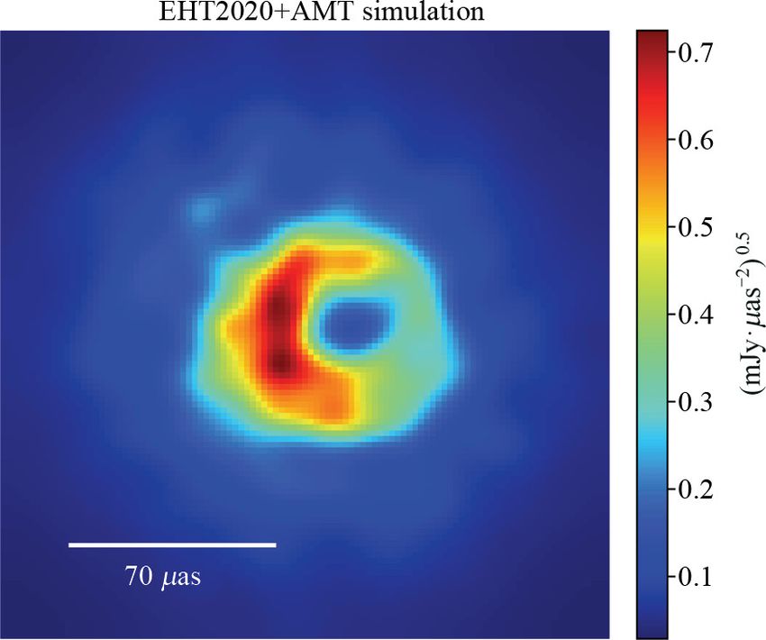
220                                                                  Chin. J. Space Sci.                    2021, 41(2)

the EHT uses hydrogen masers at all stations, and             will allow a coherence time of 60 s minding that (i)
through comparison with GPS over long timescales              the performance difference of RadioAstron and ACES
determines small fractional frequency offsets between          masers is 1.5 times on timescale 1–1000 s, (ii) there is
the masers.                                                   a difference between the goals in ACES, DSAC, and
     Frequency stability can be characterized by the          VLBI Millimetron/RadioAstron, and (iii) the EHI is
Allan deviation, a figure of merit that characterizes          a mission concept. This coherence time (60 s) is there-
the relative standard deviation in frequency of a clock       fore used in our imaging and sensitivity calculations
referenced to a perfect reference clock over a range of       throughout this paper instead of the more conser-
different time scales. To maintain phase coherence,            vative value of 30 s. This coherence time (60 s) is
the Allan deviation for a given time interval multi-          shorter than the (u, v)-grid cell crossing time (71 s–
plied by the observing frequency and the integration          7.5 min, see Subsection 3.3), and hence the phase sta-
time should be limited to less than one radian (see           bility falls under case 4 in subsection 3.4. In order
Subsection 9.5.2 in Ref. [17])                                to upgrade from case 4 to case 3 or even 2, either a
                                                              connected local oscillator architecture (see below) or
                    2πfc τ σy (τ )   1,                (2)
                                                              a three-satellite system allowing for the measurement
where σy (τ ) is the Allan deviation, fc is the center fre-   of closure phase is required.
quency, and τ is the integration time in the interfero-             The coherence time of 60 s constrains the allowed
meter, while a more exact expression for coherence            integration time (Subsection 1). However, it is longer
time is in Ref. [35]. At fc = 500 GHz, the required           than the atmospheric limit for ground-based observa-
Eq. (2) Allan deviation of each ultra-stable oscillator       tions, even as compared to an observation frequency
is below 3.8×10⁻¹⁵ (Hz/Hz), at integration time 60 s.         band that is several times lower[64,65] . This is an asset
      The heritage of ESA’s ACES, existing and space-         of a space-space VLBI system at 500 GHz.
proven ultra-stable oscillators, includes the best-                 A connected-LO architecture may be required to
known space hydrogen maser[61,62] . This maser satis-         improve the instrument coherence. One such scheme
fies the requirement Eq. (2) on timescale up to 10 s,          is as follows: master LO signals, generated on the
but it is 1.7 weaker than this requirement at 60 s.           different satellites, are inter-changed across each pair
      The loss of interferometer coherence(Eq. (14),          of satellites and locally mixed to generate a summed-
Eq. (18) in Ref. [35]) due to use of two such masers          frequency signal that is coherent across all of them.
is within 16% on timescale 30 s (35% at 60 s). The            The inter-satellite paths used for the exchange of sig-
coherence loss on a timescale of 1–10 s is within 6%–         nals and LO components on each baseline are sym-
8%. A better performing space-proven ultra-stable             metrical and hence, each satellite has access to the
oscillator is not known.                                      same summed clock signal with the only difference
      The multi-pole linear ion trap frequency stan-          arising from frequency variability on the signal pro-
dard satisfies the requirement Eq. (2) on timescale up         pagation timescale between satellites (amounting to a
to 35 s, but it is 1.5 times weaker than this require-        maximum of ∼0.1 s). The achievable coherence time
ment on 60 s[63] . The loss of interferometer coher-          when using such a LO-sharing scheme is a subject of
ence(Eq. (18) in Ref. [35]) in case of use of two such        current research.
frequency standards is within 16% on a timescale              3.6 Telescope Requirements: Antenna
up to 35 s (29% at 60 s). The coherence loss on a                    Size, Bandwidth
timescale 1–10 s of is within 0.4%–4.2%.                      As our aim is to keep the EHI cost-effective, we here
      The expected performance of the future Mil-             consider that all satellites are launched together. The
limetron dedicated maser[64] (provisional launch in           chosen observing frequency, of 500 GHz or higher,
2028) is 2 and 1.5 times better than of ACES maser            makes the option of a deployable antenna system chal-
on 10 s and 300 s, respectively. The smallest factor of       lenging if practical, so we only consider the options
1.5 allows an EHI coherence time slightly above 60 s          for a static antenna here.
(Eq. (18) in Ref. [35]).                                            Such high-frequency band challenges the ultra-
      We assume that a future ultra-stable oscillator         stable oscillators Eq. (2), constrains the integration
Kudriashov V et al.: An Event EHI Mission Concept Utilizing Medium Earth Orbit Sub-mm Interferometry 221
time to 60 s, and motivates the use of the closure of 5 GHz. Assuming that the system observes two
phase[60] to mitigate individual station-based phase orthogonal polarisations at 2-bit Nyquist sampling,
errors. we get a corresponding aggregate raw data rate of
The latter requires three science instruments em- 5 × 109 × 2 × 2 × 2 = 40 Gbit·s−1 to be transmitted
barked on separate satellites. The Ariane 6 fairing between satellites.
diameter allows up to 4.0 m main reflectors, using a The highest data rates for any space commu-
Cassegrain configuration (Figure 5). nication link that have so far been demonstrated
The system sensitivity will be accordingly limi- are 5.6 Gbit·s−1 and 1.8 Gbit·s−1 over distances of
ted: using an aperture diameter of 4.0 m, an estima- 5100 km (LEO–LEO) and 45 000 km (LEO–GEO),
ted system temperature of 150 K, and a total system respectively[72,73] . The next generation of the op-
efficiency as described in Ref. [46] we get a System tical space communication terminals aim to reach
Equivalent Flux Density (SEFD) of 6.8 × 10⁴ Jy for a data rate of 1.8 Gbit·s−1 over distances up to
each of the antenna systems. For comparison, the ∼80 000 km[74] .
median SEFD values for the EHT stations during the Ongoing developments will push this figure to
2017 observations range from 74 for Atacama Large higher values. ESA’s program Advanced Research
Millimeter Array to 1.9 × 10⁴ Jy for the South Pole in Telecommunications Systems (ARTES) includes a
Telescope[16] . number of activities (with Synopta-CH, AirbusDS-
The low correlated flux density expected from Fr, TNO-NL) to develop terabit links for future
our main sources on long baselines poses a challenging communication satellites using Wavelength Division
sensitivity requirement and hence, the widest possi- Multiplexing (WDM) technology with the aimed ca-
ble observing bandwidth is desired. Existing Earth- pacity of 10 Gbit·s−1 per carrier wavelength[28]. A
bound telescopes operating at mm bands process in- new project High Throughput Optical Network (Hy-
termediate frequency bandwidths of 4–8 GHz[66−68] . dRON), also under preparation by ESA[28] , aims to
The latest developments in mm and sub-mm recei- demonstrate 0.1–1 Tbit·s−1 bidirectional space op-
ver technology allow an intermediate frequency band- tical link capability, among other goals, and the
width up to 22 GHz[69,70] . The widest-possible band- planned demo-phase is in 2023–2025. The above men-
width is desired to recover the sensitivity. However, tioned next generation of optical space communica-
the bandwidth poses requirements on the real-time tion terminals (under development in TESAT) is one
knowledge of the DnDR model[71] and the achievable of the major developments[74] . Ranging can be imple-
values are expected from Ref. [36]. mented in optical communication terminals addressed
For the EHI, we take a processed bandwidth in Ref. [74].
Fig. 5 Accommodation of EHI satellites in Ariane 6222 Chin. J. Space Sci. 2021, 41(2)
of 5 µas towards Sgr A*, at 71 s (see 60 s in Subsec-
tion 3.5). More challenging performance is required
for the target resolution (5 µas) at this 7-sigma detec-
tion threshold. For example, a receiver noise temper-
ature 50K and observation bandwidth 10 GHz would
still require a 20 m main reflector which isn’t feasible
at surface accuracy below 10 µm and at a cost-efficient
mission. Narrowing the DnDR search window sizes
is promising to decrease the detection threshold and
other source models, see models 16, 31, 39 and Fig-
ure 3 in Ref. [46], feature several times lower flux den-
sities and hence, indicate additional challenge for this
Fig. 6 Plotted in green: expected correlated flux
development avenue.
density as a function of baseline length for one of the
models for Sgr A* (model 24), using radial bins in the
The relative positioning is little explored on
(u, v)-plane. The continuous blue line shows the system Medium Earth Orbits, while the perfect knowledge
noise floor for an integration time of 60 s. In cyan, the of DnDR model (instrument baseline state vector,
sensitivity following from the maximum integration time translation between phase centers of antennas, dif-
allowed by (u, v)-smearing is shown with a maximum ference in local oscillators) allows image reconstruc-
allowed integration time of 7.5 min tion without any detection required beforehand, as
demonstrated in the ESA SMOS[26,75] . In case the
3.7 Sensitivity coherence timescale is longer than the observation cy-
To estimate the visibility noise for a given obser- cle, the uncorrelated noise can get averaged out by a
ving bandwidth and integration time, we use the number of observation sessions as mentioned in Sub-
standard[17] expression: section 2.3 in Ref. [46].
1 S1 S2 The EHI concept[50,56] aims to relax the detec-
σ= , (3)
0.88 2Bτ tion requirements by the involvement of relative navi-
where σ indicates the system noise level in Jy, 1/0.88 gation and connection of ultra-stable oscillators. As
is the standard Van Vleck 2-bit quantisation correc- above mentioned, a detection might not even be nee-
tion factor, terms S1 and S2 indicate the system equi- ded at all, if the orbit determination is accurate eno-
valent flux densities (in Jy) of the two stations, B is ugh (e.g. with a 3D baseline state vector accuracy
the observing bandwidth in Hz, and τ is the integra- of a fraction of the observing wavelength, see Sub-
tion time in seconds. section 3.2). Refined knowledge of the baseline state
Given the choice of orbital plane and orbital ra- vector, available a posteriori (as reconstructed from
dii, we will get maximum projected baseline lengths an advanced relative orbital propagation model), po-
towards our prime sources in the range from 47 Gλ to tentially allows us to reduce the DnDR search win-
53 Gλ, at 690 GHz. The expected correlated flux den- dow for fringe fitting, correspondingly improving the
sity for Sgr A* on these long baselines, obtained from detection threshold. Once the detection is success-
our source models[46], is lower than 30 mJy (Figure 6). ful, further improvement in visibility SNR may be
The integration time required to achieve a 7-sigma achieved by coherent averaging of visibilities within
detection on a baseline of 50 Gλ is 6 h, while EHI each (u, v) grid cell provided that the coherence time
baseline vector crosses the corresponding (u, v)-grid is not shorter than grid cell crossing time. Alterna-
cell on 71 s (see Subsection 3.3) and hence, obtaining tively, bispectra[60] may be formed from the visibili-
a detection at the longest baselines is not feasible. ties and averaged over multiple epochs.
Baseline shortening allows longer integration Assuming that the navigation study disables
time Eq. (1), but limits the angular resolution and blind selection of the data bin, detections for Sgr A*
hence, prohibits the principal science goal. In detail, are limited to the shorter baselines, this does not hold
the achievable baseline length allows 19 µas instead for other sources (see e.g. Table 1). All of the AGNKudriashov V et al.: An Event EHI Mission Concept Utilizing Medium Earth Orbit Sub-mm Interferometry 223
sources besides Sgr A* and M87* are expected to be much longer time scales required to yield sufficient
more compact in terms of their size on the sky, and SNR.
several of them are actually brighter in total flux den- The on-board (first stage) accumulation pe-
sity (e.g., 3C273 and 3C279). This means that we riod is limited by the accuracy of the real-time
can expect higher correlated flux density levels on delay model, see Eq. (3) in Ref. [71]. We assume
long baselines for several of these sources, making de- in Subsection 3.9 that real-time positioning accu-
tections possible further out in the (u, v)-plane and racies (1-sigma) of delay-rate and acceleration in
offering a higher angular resolution for those sources. 3D relative coordinate system are smaller than
3.8 Correlation Scheme ∼60 ps·s−1 (1.7 cm·s−1 baseline velocity) and ∼80
A downlink of electric field signals would allow versa- ps·s−2 (2.5 cm·s−2 baseline acceleration), respective-
tile re-processing and the required downlink data rate ly. This allows an accumulation period of 0.3 s, at a
is 40 Gbit·s−1 (see Subsection 3.6). Such data stream bandwidth of 5 GHz (0.1 ns Nyquist sample rate).
can not rely on radio frequency allocation bands for At an observed frequency of 500 GHz, an on-
the downlink of space research data from MEO (those board integration time of 0.3 s dictates that the delay-
feature width up to 1.5 GHz, see Ref. [76]) in S-, X-, rate resolution be 6.67 ps·s−1 and a delay-rate window
and Ka-bands, and on-ground stations supporting of 34 samples (±3.4 cm·s−1 ) is required (113 samples
those. The W-band allocation (within 74–84 GHz) at a higher delay-rate resolution 2 ps·s−1 ). Assuming
is not capable enough too and moreover, the modula- centimeter-level accuracy in the projected baseline
tor technology for such a wide-band is challenging[29]. length, a delay window of the order of a few samples is
For these reasons, the electric field data must be ex- sufficient for the observation signal coherence length
changed between satellites and correlated on one of down to 6 cm, at bandwidth 5 GHz. The length of
them. the delay window should allow also for the spectral
In order to cross-correlate the sampled signals resolution required to calibrate for the instrumental
from the different satellites with the right delay mo- bandpass shape, and for digital sideband separation,
del, accurate knowledge of the 3D baseline vector and see e.g. Ref. [77]. A coarse spectral resolution allows
its time derivative(s) is required. Perfect knowledge narrowing the search window to reduce the down-
of this baseline geometry would allow us to blindly link data rate. A delay window of 40 samples ena-
pick the correct correlation peak from the correlated bles calibrating for 500 MHz-scale (10% bandwidth)
products at all times. In reality, this will not be the spectral features in a 5 GHz band width. This delay
case: residual errors in satellite positions and veloci- window width is narrowed using Hermitian symme-
ties mean that we will need to use a DnDR search try at the output of the Fourier transform, and kee-
window. ping both unique real-valued numbers on 0 Hz and the
We adopt a usual VLBI processing architecture Nyquist frequency. The search window size number is
wherein the first stage computes the cross-correlation 21 × 34 = 714 (21 × 113 = 2373 at 2 ps·s−1 ). The out-
across a range of values in DnDR over relatively short put data rate to be transmitted to the ground in this
accumulation periods using an a-priori delay model, scenario is of 3 × 2 × 4 × 21 × 34 × 32 = 550 kbit·s−1
and the second stage solves for the residual DnDR per 5 GHz band width, accounting for baselines be-
(fringe finding), thus allowing integrating over longer tween 3 satellites (or 3 observation frequencies), 4
time scales, see Subsection 9.2 in Ref. [17]. In this polarization, 2 quadrature products, and 32-bit da-
proposed scheme the first stage of processing is to ta (1.8 Mbit·s−1 at 2 ps·s−1 ).
be done on-board the satellite stations using a delay This data rate is ∼438 000 times smaller than it
model based on real-time orbital information. The would be in the case of electric field signals (132 000
data product of this stage is then transmitted to the times at 2 ps·s−1 ). This data rate fits any of the
ground station, where the second stage proceeds us- aforementioned S-, X-, Ka-band allocations and al-
ing a more accurate delay model based on orbital re- lows EHI to benefit from ground stations supporting
construction which allows coherent addition over the those. This is an asset of being able to perform the224 Chin. J. Space Sci. 2021, 41(2)
first stage of processing on the fly. ery ∼100 samples, and partial fringe rotation would
In case a wider downlink is needed in future, the likely need to be done in the analog domain.
Shannon–Hartley theorem sets the upper bound for 3.9 Relative Positioning
the (Additive White Gaussian point-to-point) com- The feasibility of the correlation scheme described
munication link capacity equal to ∼5.2 Gbit·s−1 , at a above is dependent on having knowledge (not control)
link budget of (SNR) 10 dB and within this allocated of the inter-satellite baseline vectors with centimeter-
frequency band width of 1.5 GHz (the margin’s upper level accuracy in orbit, and sub-mm level accuracy
bound is 3 orders of magnitude between 5.2 Gbit·s−1 on ground. A candidate set of Altitude and Orbit
and 550 kbit·s−1 ). Determination Systems (AODS) is in Subsection 2.3
The second stage of this processing scheme is of Ref. [36], and the ongoing industrial study is dedi-
dedicated to adjusting and averaging-up (within the cated to refine it; the translation from the measure-
coherence time) the downlinked DnDR search win- ments with a refined set of AODS, GNSS receivers,
dows according to the positioning knowledge avail- and inter-satellite metrology to the satellites’ centers
able after precise relative orbit reconstruction on the of masses (and the need or not for it) and, finally, to
ground. The latter adjustment includes a correction the phase center of the interferometer is the the sub-
of the DnDR model applied on-fly using its refined ject of the latter study, as well as the time lag between
values available on-ground. science and navigation measurements. It is unlikely
The alternative case, that the final orbit recon- that this sub-mm level of accuracy can be reached in
struction does not allow this selection, is not ad- real-time in 3D spatial coordinates, which means that
dressed in detail because the navigation study result at the time of on-board correlation the relative posi-
might allow a sufficiently accurate knowledge of the tioning accuracy just needs to be small enough (see
DnDR model. Namely, it may be assumed that in both cm-level and downlink margin in Subsection 3.8)
this alternative case of detection (a) a false alarm to provide DnDR search windows of a reasonable and
rate of 1 in 100 is acceptable and (b) the correlator limited width. With a-posteriori relative orbit deter-
output values are normally distributed and hence, a mination accuracy, the correct DnDR bins may then
number above a threshold of 2.58-sigma might be a be selected on the ground. Note that, if the quality
signal. This threshold level constraints the longest of a-posteriori relative positioning (including phase
baseline (Figure 6) and hence, precludes the aimed center tracking) is sufficiently high, the correct bin
angular resolution. The on-going navigation study[36] in the DnDR search window may be picked “blind-
may result in an orbit reconstruction accuracy that ly” without needing to obtain a detection first. This
allows for image reconstruction with a lower SNR per is a very important point, as it potentially allows us
(u, v)-point. to use longer effective integration times for (complex
For orbits that meet the requirements described visibilities or) bispectra by coherently adding them
above, the maximum digital delay required to align together over multiple epochs.
the voltage data stream digitized on one satellite with At this point, we can consider specific numbers
the data stream received over the ISL from another for the quality of relative positioning needed for EHI.
satellite is of the order of 100 ms, or a few Gbits per As derived in the preceding section, to successfully
5 GHz band width. The maximum rate of change perform cross-correlation with an integration period
in the delay is of the order of 10 µs·s−1 , or equiva- of 0.3 s in space the real-time delay-rate and accele-
lently for integer sample delay, an increment of one ration need to be known to a precision of 1.7 cm·s−1
per hundred thousand. Limiting the loss due to sub- and 2.5 cm·s−2 , respectively. For the second stage of
sample delay errors[17] to below 1% can be achieved fringe finding, done on Earth after the correlation
by applying a spectral-domain correction in an FX- products have been downloaded, a different (better)
architecture, which would require updating once ev- a-posteriori baseline knowledge is needed. In order to
ery ∼10 FFT windows. In order to limit fringe rota- have the capability to blindly pick DnDR solutions
tion loss[17] to an acceptable level requires updating using a-posteriori orbit reconstruction information,
the fringe rotation phase at a rate of up to a few ev- the baseline vector knowledge needs to be known toYou can also read