An intermediate guide to operation of the latest CROME engine tuning and ROM editing software
←
→
Page content transcription
If your browser does not render page correctly, please read the page content below

An intermediate guide to operation of the latest CROME engine tuning and ROM editing software

© 2012 GravityLabs, Inc. CROME (Cui’s ROM Editor) v1.6.5 User Manual revision 2.1 Nov 5, 2012 by Miles David
CHAPTER 1. REQUIREMENTS
Please visit www.TuneWithCROME.com to download the latest CROME software and read this
manual thoroughly for proper operation.
1 GHz processor, 512 MB RAM, 5 MB hard disk memory
Windows XP Service Pack 2 or newer Microsoft-based operating system
Honda OBD1 EPROM modified ECU with the J12 internal jumper removed
One of the following EPROM burning or emulating devices:
- Moates Burn1 or Burn2, Xtronics Pocket Programmer, Willem PCB3 or newer
- Moates Ostrich or Ostrich 2.0 emulator, Xtronics ROMulator
One of the following datalog header connections:
- Moates Hondalog or Xtreme Hulog adapter, or Nokia DKU-5 USB adapter
Any available wideband O2 sensor controller
A purchased CROME license and registration string is necessary for the purposes of this manual,
as the advanced tuning section focuses primarily on the Gold ROM platform.
INDUSTRY PREFERRED APPLICATIONS
Although not required, CROME Gold files cannot be accessed without a Pro license, and cannot be saved
or burned to an EPROM chip without a Dealer license. Keeping this in mind, the following options are
provided based on common known-working combinations used in the tuning industry:
1. CROME Pro (single-use) License ($149) with Moates Ostrich emulator ($175)
2. CROME Dealer License ($450) with Moates Ostrich or Burn2 ($85)
3. The Moates Demon RTP can be considered for use with CROME 1.6.5 but it is known to have
connection issues on some laptops for no apparent reason. Some tuners are able to make this
combination work well, and theoretically it is ideal, however the success rate is negligible. Using
a 1msec latency time may resolve connection conflicts.
- Hulog/HondaLog USB adapter
- AEM UEGO, Innovate LC-1, or PLX wideband O2 sensor controller
- Windows XP laptop with at least 2 USB ports, 1GB RAM
- Tip: HP laptops often get very hot, which can be uncomfortable for tuning. It is not
recommended to use an HP laptop to tune a vehicle, including HP tablets.
© 2011 GravityLabs, Inc. CROME (Cui’s ROM Editor) v1.6.x User Manual revision 2.0 March 10, 2012 by Miles David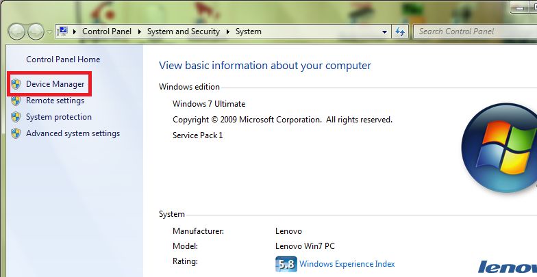
CHAPTER 2. SETUP AND CONFIGURATION
    1. Download the latest version of CROME at www.tunewithCROME.com and opt to open CROME
       after installing; the welcome screen should give an option to select [Register]. If not, navigate
       the menu bar to Help » Register.
    2. In the Registration window, select [Get Reg String] at the bottom, which directs you to the
       CROME website to complete your registration. Once you’ve purchased and acquired your Reg
       String, copy and paste it into the Registration window and select [Register].

    3. The Nokia USB Datalogging setup is rather involved, and users should refer to the following URL
       for proper directions: http://forum.pgmfi.org/viewtopic.php?t=1663
    4. Moates Datalogging cable drivers are supported through FTDI, and the latest package can be
       found here: http://www.ftdichip.com/Drivers/CDM/CDM20814_WHQL_Certified.zip
    5. After installing drivers, right-click on My Computer and select Properties from the menu

              a. For XP machines:

© 2011 GravityLabs, Inc. CROME (Cui’s ROM Editor) v1.6.x User Manual revision 2.0 March 10, 2012 by Miles David
b. For Vista/ Windows 7 machines:
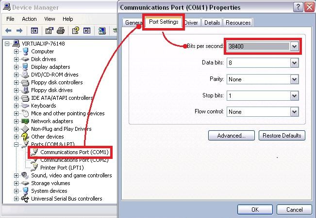
6.) While in the Device Manager, locate and expand the Ports (COM & LPT) tree and plug in the
datalogger USB. The device should appear under the tree as USB Serial Port (COM___). Double-
click the port to open Properties. Change the Bits per second (aka baud rate) to 38400, Click
[Advanced] and change Latency from 16 to 1, select [OK] twice to return to the Device Manager.
© 2011 GravityLabs, Inc. CROME (Cui’s ROM Editor) v1.6.x User Manual revision 2.0 March 10, 2012 by Miles David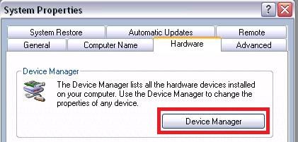
7.) Open CROME, and navigate the menu bar to File » Settings or click on the Settings icon in the
        toolbar. Select the Tuner Comm tab and set Serial Protocol to Crome QD3 or QD2, unless you’re
        using an older ROM/firmware version. Make sure the Port number and Baud matches the
        Device Manager profile, as shown below:

    8. Move to the Real Time Programming tab, if equipped with a Moates, Xtronics, or PGMFI product
       (Willem and other EPROM burners use external software to program ROM files). Connect the
       EPROM burner first, and observe which port is designated for it in the Device Manager. If you are
       only equipped with an emulator or Moates Demon RTP, treat it as your chip burner for this step:

© 2011 GravityLabs, Inc. CROME (Cui’s ROM Editor) v1.6.x User Manual revision 2.0 March 10, 2012 by Miles David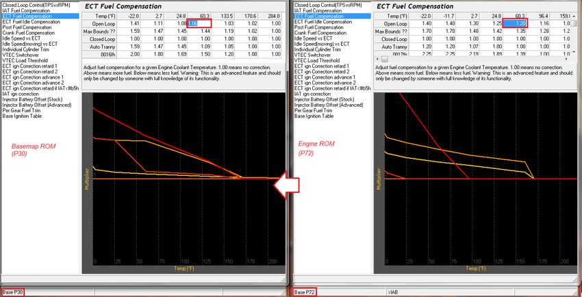
8.5 (continued) Select the proper hardware and port (COM number will be black if it’s available). The
        Baud rate for most RTP and Burn hardware is 920000; however Xtronics Baud rate is usually
        115200. Open the properties of the associated port in the Windows Device Manager and change
        the Bits Per Second to 920000 (or closest given value, may be shown slightly higher).
            1. Even if using the Ostrich or ROMulator, select the tick box Used for 27SF512 unless you
                 are specifically using an obsolete 27SF256 chip with a Moates or Xtronics chip burner.

    9. If you are using a chip burner and emulator by the same company (i.e. Pocket Programmer and
       ROMulator, or Burn2 and Ostrich 2) unplug your chip burner and observe the new port number
       in Device Manager while connecting the emulator. Otherwise, skip this step.

         If you are using a chip burner and an emulator by different manufacturers, refer to step 8 and
         set up the second device using a unique port number. Again, available ports are shown in black
         under the port list in CROME settings.

         Double-click the properties for the port, select the Port Settings tab and click the [Advanced…]
         button. At the bottom, change the port number to the same port that was designated for the
         chip burner – this allows the user to swap devices without having to constantly change the port
         settings in CROME

* This is the same process used by Gravity to configure personal and commercial laptops. If these
procedures do not work, refer to the troubleshooting section of this manual or www.PGMFI.org for
more technical information on this process.

© 2011 GravityLabs, Inc. CROME (Cui’s ROM Editor) v1.6.x User Manual revision 2.0 March 10, 2012 by Miles David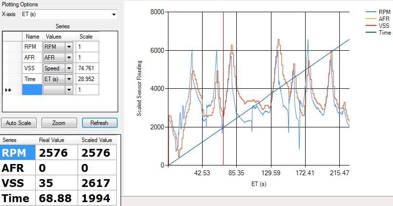
CHAPTER 3. BASIC ROM EDITING
For the purpose of this manual, many fundamental and integral elements of ECU theory and tuning have
been omitted, as this manual focuses primarily on the functionality of the CROME program. Please visit
www.PGMFI.org for in-depth technical details and full explanations on the nature of this program.

         Examining basic features:
            a. Tables (F2) – these reference the MAP sensor to detect load, and the Engine Speed
                (RPM) sensor to find a value the ECU will can calculate to log data and send signals.
                Two of the tables are used constantly to run the motor: Fuel, and Ignition Timing (F5/F7)

                  The secondary tables (F6/F8) are used for Vtec/nitrous/methanol/etc. to control fuel
                  and timing under different conditions that are not consistent and require an output to
                  be engaged. This will be explained more later on.

                  Duty cycle determines if your injectors can handle the application’s power
                  requirements, and can also explain fuel cut. If the duty cycle of your basemap (which
                  should always be richer than necessary) exceeds 80%, invest in larger fuel injectors
                  and/or other fuel system components to increase flow and reduce the pulse duration.

© 2011 GravityLabs, Inc. CROME (Cui’s ROM Editor) v1.6.x User Manual revision 2.0 March 10, 2012 by Miles David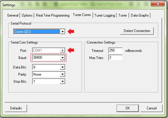
Ignition tables (F5/F6) are relatively consistent, with the general rule of thumb that the
                  more torque (larger fuel value) in any given cell, the mixture will reach peak combustion
                  faster, needing less timing advance. It is strongly advised to have a full understanding of
                  combustion and detonation (engine knock) before modifying this region.

              b. Graphs (F3) – Useful for observing tables in a more fluid form to estimate peak torque,
                 cross-reference fuel and timing relationships, and easily identify any kinks or glitches in
                 tables that may cause erratic performance. More detail will follow in later chapters.

Graphs are essentially turned 90° counterclockwise from the tables, although timing lines will appear
inverted since ignition values usually decrease as fuel increases; with graphs, MAP lines move
independently rather than fixed like columns.

© 2011 GravityLabs, Inc. CROME (Cui’s ROM Editor) v1.6.x User Manual revision 2.0 March 10, 2012 by Miles David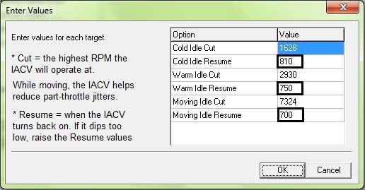
CHAPTER 4. PLUGINS AND ROM OPTIONS (F4)
         For non-Gold files (other than P13) only the supported P30 ROM will be used for demonstration.
         Before continuing with any P30 based file options, select Plugins » Enhancements » Remove
         Checksum Routine. This tells the ECU to ignore errors when files contain more information than
         the stock program.
         1. Select Plugins » Enhancements » Add Extra Features to install more controls to the Options
             menu. These are basic desirable features for Honda tuning. Select Options (F4)

                        In order by section, here is the relevant detail for each function:
         2.   Rev Limiter – applies to the secondary tables if VTEC is enabled. The fuel is cut at the
              specified value and is restored at the RPM value specified in the Settings window.
         3.   Idle – controls the IACV (Idle Air Control Valve) which allows air to pass around the throttle
              body. This should only be adjusted if the engine dies during deceleration or when idling,
              especially with aggressive cams or individual throttle bodies.
         4.   VTEC – dictates when the VTEC solenoid is activated and the secondary tables are used. IAB
              is only enabled with the P72 and P13 ROM specifically for use with P72 and P13 ECUs in
              conjunction with either the B18C1 GSR motor or the H22A motor. Tuning this feature will be
              covered in later chapters.
         5.   Speed Limiter – uses fuel cut to limit speed in the same manner as rev limiting. This can be a
              beneficial feature for emissions or security when using dual chips.

© 2011 GravityLabs, Inc. CROME (Cui’s ROM Editor) v1.6.x User Manual revision 2.0 March 10, 2012 by Miles David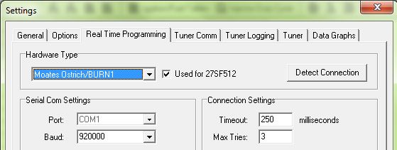
6. Launch Control – sets a rev limiter that is only active between 0-8mph to assist in smooth
launching and building boost with turbo applications. It can only be perfected through
tuning trial.
7. Full Throttle Shift – engages a rev limit at 100% throttle while the clutch is depressed to rev-
match the engine for the next gear to save time over heel-and-toe shifting. At redline,
determine at what RPM the next gear picks up and set the value. See Attachment #2 for
help. Be advised this feature in standard ROMs only works if the clutch button is wired to
the A/C circuit pin B5 on the ECU. If the FTS rev limiter is always engaged, see
troubleshooting.
8. Shift Light – provides a reminder to upshift that’s sent to the Check Engine Light in the dash
cluster when nearing the end of peak power. Depending on gearing/ speed and reflex, this
may need to be set lower than the actual peak power range.
9. Boost Limit – provides a fuel cut for boost protection over a certain value. Usually used to
identify the ROM or MAP sensor’s highest threshold before the values exceed measurable
limits. This is NOT to be used as an alternative to a wastegate to stabilize boost.
10. Sensors – many applications and/or ECUs do not have all available sensors that the P30
offers, so disabling (checking) those removes the Check Engine Light & resulting trouble
code and removes the input data from the ECU’s calculations. Especially for tuning, it is ideal
to remove variables such as the O2 which skews wideband readings, the Barometer which
skews the MAP sensor, and the ELD which shifts the injector pulse offset.
Other selections in the Plugins » Enhancements tree include:
11. Rev Tools – Extends the RPM table range to 11,000 RPM for high-revving motors.
12. Edit Gear Correction – obsolete, can now be changed in Advanced Tables.
13. Edit Gear Table – same as above, designed by a different author.
14. Step Ignition Retard – applies reduced timing to specific ranges of boost to the tables. The
default settings are good for most mid-power applications, however for hotter-running or
less-efficient boost setups the values should be reduced more rapidly. This is an advanced
tuner function that should be practiced with extreme caution without experience.
15. P30 Option Byte Hack – if options are not working properly or the ROM is causing a solid CEL
16. Quick Datalogger +RTP – should be applied to every file where datalogging will be used.
Without this plugin, the ECU does not translate data correctly to be deciphered by CROME.
17. VTP+VTS Remover – use with caution; if the engine does not have a VTP or the VTP/VTS is
acting improperly, it can be disabled here. The VTP return wire needs to be grounded out.
18. Plugins » Utilities » Calibrate Non-Honda TPS – Works with the P30 ROM to adjust a TPS that
has 0% and 100% throttle values different from the 0.5v and 4.5v norms. This is a common
utility and often solves several troubleshooting concerns. It can tuned by either reading
direct voltages, or datalogging open & closed throttle (with the key on & engine off), and
adjusting the plugin values until readings show ≤0% and ≥100%
© 2011 GravityLabs, Inc. CROME (Cui’s ROM Editor) v1.6.x User Manual revision 2.0 March 10, 2012 by Miles David Selections in the Plugins » Control tree include:
19. Advance Idle – useful for bogging and dying when decelerating or with aggressive cams.
Most performance motors will need higher idle resume, although there is no generic
profile. Cams and applications with heavy fuel flow that don’t operate well under leaner
conditions or low RPM will often try to rev even during idle, so idle cut values may need
reduction if surging is too extreme.
20. ABT+ Map Cutoff – seemingly for older engines using a “missing link” hack on a stock MAP
sensor. There is no modern application where this unit is used, as it has been deemed too
dangerous and unreliable.
21. ABT+ Close Loop MAX Load Edit – adjust what the highest MAP value the ECU will use the O2 for
adjusting AFR to 14:1 (P30 ROMs do not reference the Lambda table to adjust fuel).
22. Advanced VTEC Setup – allows user to set specific VTEC points depending on engine load. Useful
for road racers, although only accurately tunable on a load-bearing dyno. Only experienced
professionals with intimate knowledge of VTEC functionality should attempt tuning this.
23. Air Conditioning Cutoff – by setting an RPM and TPS maximum, the A/C turns clutch disconnects
and the ECU stops compensating for the A/C unit above the specified level. A good option for
daily drivers as well as programming custom outputs.
Selections in the Plugins » Misc tree include:
24. Disable/Enable IACV – engines controlled strictly by the butterfly screw, ECUs with inoperable
IACV circuits, and ITB setups benefit from this feature.
25. Select X Tranny – used for per-gear datalogging, per-gear fuel trim and custom controls.
© 2011 GravityLabs, Inc. CROME (Cui’s ROM Editor) v1.6.x User Manual revision 2.0 March 10, 2012 by Miles David Primary Plugins require thorough understanding, and are as follows:
i. Advanced BoostTools+
This tool adds additional MAP columns for boost ranges, skews the columns for aftermarket
MAP sensors, and customizes the MAP sensor voltage scale that the ECU uses to reference
tables. Navigate the menu bar to Plugins » Advanced BoostTools+ and select the MAP sensor
you’re currently using.
19. If your sensor is not shown, obtain the manufacturer’s datasheet and manually enter
the specified max and min pressures as well as your atmospheric voltage reading.
Next enter the amount of boost columns you need – generally one column for every 2psi is safe,
but if you notice fuel values don’t change significantly between certain columns you can
eliminate them and rescale the values:
The same can be done for RPM rows; just don’t change the first OR last column/row as it may
corrupt the ROM. Always be sure to save a new ROM instance before any significant changes.
You may notice the boost area is grayed out, this is normal. Toggle-On the Tuner (CTRL+T)
if the tuner bar is not at the bottom, highlight the cells, and click the Toggle Selected Cell icon:
ii. FuelTools
This should be used after applying BoostTools or ITB Tools. This skews multipliers in the ECU
related to fuel calculations and delivery. If your fuel system is modified, this is an essential tool.
After installing the plugin, navigate to Tools » Fuel Multiplier (F) and enter injector and rail
pressure information and/or any changes made in displacement.
© 2011 GravityLabs, Inc. CROME (Cui’s ROM Editor) v1.6.x User Manual revision 2.0 March 10, 2012 by Miles DavidEngine Capacity (displacement) can also be helpful for calculating fuel for new compression
ratios as a percentage difference: multiply your existing compression by 10 and enter it as Old
Capacity. Multiply your new compression ratio by 10 and enter it as New Capacity.
Next select the [Advanced] tab, note the Final Multiplier from the first page. For general
purposes, O2 and tip-in should be kept at 1.00, unless working with special fuels (E85, race fuel,
nitro). Cranking and Post-Startup should be slightly higher than the Final Multiplier.
Finally, Offset should be gradually increased in increments of 10.00 until the idle remains steady
at 14.7:1 AFR and surging ceases. This is strictly trial and error; see Injector Battery Offset before
adjusting offset. Click [OK] and the multipliers will be applied to the rom.
iii. ITB Tools Plus Jr 0.1
Use with extreme caution tuning ITBs with standard ROMs; it is HIGHLY recommended to use a
Gold base file for tuning Alpha-N, however it can still be done proficiently with a P30 base.
The remainder of ITB calibration is outlined in Chapter 8.7
Unused Plugins can be removed or rearranged in the menus by selecting Plugins » Plugin Manager
and selecting individual scripts by their file name. To add or reinstall a plugin, simply click [Install New
Plugin] and search the directory.
© 2011 GravityLabs, Inc. CROME (Cui’s ROM Editor) v1.6.x User Manual revision 2.0 March 10, 2012 by Miles DavidCHAPTER 5. TOOLS AND SETTINGS
1. Advanced Tables (L) – this tool is explained first, as it is relevant to comprehend in order for
the next topics to be properly understood. This is only available on standard ROMs, but the
tables are also implemented in the CROME Gold ROM. Proceed to Tools » Advanced Tables
a. Closed Loop Control – focus on the CUT curve first; for the most part, the RES curve will
always have slightly lower values. Determining these triggers should be based on when
the O2 is no longer functional, such as any target AFRs richer than 14:1.
b. IAT Fuel Compensation – cold air is denser, and needs more fuel to maintain proper
mixture. This, along with most fuel and timing scales, should be datalogged thoroughly
from stone-cold to heat-soaked and plotted on a graph to derive percentages. Motors can
benefit from adjusting this scale for rough cold-starting or if excessive fuel fluctuations
occur during warm-up. Adjustments should be made based on percent, as 1.00 = 100%,
0.94 = 94% and so on.
c. ECT Fuel Compensation – the same concept from the IAT, but more involved:
o Open Loop – any terms when the O2 is not compensating for fuel, or if the O2 is
disabled. Tuning is reliant on IAT, so both of these values should be plotted together
to determine which should be scaled more aggressively.
o Max Bounds – high load at colder temps usually needs more fuel, so these values
should always be higher than Open Loop.
o Closed Loop – since the O2 compensates fuel on its own, this should usually stay at
1.00 (100%) unless the fuel needs at the point where system switches to closed loop
are still more than 25% above normal.
o Auto Tranny – if applicable, the ECU will use this table instead of any other tables, as
the torque converter has a different method of distributing load. If excessive gear
switching is noticed, try adding compensation.
o 0016fh – this number is the hex address on the chip for where this scale is found, but
so far there’s been no development on what it’s for.
d. ECT Fuel Idle Compensation – really only for minor adjustments during idle, or within the
Resume range of the IACV.
e. Post Fuel Compensation – a simple map that the ECU uses right after starting the engine
until the ECU collects enough useable information from the ECT/IAT.
f. Crank Fuel Compensation – useful for ironing out cold-start issues. Start excessively lean
and gradually add pulse width. Do the same for Post Fuel if the engine doesn’t stay
running or hesitates/gurgles.
g. Idle Speed vs. ECT – helps warm the engine during colder operation. Rarely should this
ever exceed 2000 RPM. Standard cold-hot is approximately 1500-750.
h. Idle Speed (moving) vs. ECT – helps protect the engine from dying and helps synchronize
gears while switching from neutral to gear. Advance only if necessary. If you find it difficult
to engage gears from neutral while moving, reduce these speeds.
© 2011 GravityLabs, Inc. CROME (Cui’s ROM Editor) v1.6.x User Manual revision 2.0 March 10, 2012 by Miles Davidi. Individual Cylinder Trim – sometimes used for changing the fuel multiplier without
changing duty cycle when importing custom ROMs to a new file. It’s NOT recommended
to do this unless you are highly experienced. Otherwise, some motors (especially B series)
can run leaner in one cylinder, so this allows the ROM to compensate and prolong the life
of the motor as well as increase power. VERY dangerous to modify without datalogging
EGTs for each cylinder.
j. VTEC Switchover – much like the plugin, the best way to tune this feature is on a dyno,
although fuel graphs can be used as well. This is the point the ECU signals the VTEC
solenoid to engage, and switches the ROM to the secondary tables. VTEC tuning is
explained in later chapters.
k. VTEC Load Threshold – divides the VTEC crossover point dependent on a MAP value.
Beware that the table is backwards from the graph orientation here. If having trouble
getting VTEC to switch properly, try lowering the mbar values on the lower RPM range.
This feature takes practice, it’s recommended to start with values just above the O2
Closed Loop cutoff point.
l. ECT ign Correction Retard 1 – high load ignition dampening for overheating. Only modify
this if there is significant power loss/ engine knock during heat soak.
m. ECT ign Correction Retard 2 – do not change these values.
n. ECT ign Correction Advance 1 – high load ignition advance; colder combustion usually
benefits from higher advance. Tune this as you would the ignition tables, starting from
stone-cold to heat-soaked.
o. ECT ign Correction Advance 2 – low load ignition advance, same process.
p. Retard if IATs. Injector Battery Offset (advanced) – no longer used, do not alter this table.
t. Per Gear Fuel Trim – some ROMs default at 2.00 (200%) in this section, so be aware of this
when importing tables from another ROM. It’s best to change this to 1.00 (100%) right
away, as 200% is the maximum value however it’s ideal to have more fuel in lower gears.
This is where the Individual Cylinder Trim tool can be used to set all 4 cylinders at 200%.
With this tool, it’s best to tune 4th (or the closest 1:1) gear perfectly. Then run a datalog
for each gear independently. Compare AFR results, and adjust accordingly. 1st and 2nd gear
should almost always run richer, and for daily drivers 5th gear can afford to be a few
percent leaner.
u. Base Ignition Table – a useful option for global timing changes for a broad RPM range. This
can save time while tuning engines that are expected to require a lot of ignition changes,
rather than changing individual cells. This should really only be used if the engine has a
drastically different timing curve, such as an H22 imported to a P30.
2. Tools » Fuel Multiplier – as explained in Chapter 4 as a plugin for non-Gold ROMS, this tool is
also integrated in the CROME Gold ROM under the Options tree, which we will explain here.
With an open CromeAu Base file, select Options (F4) and perform the following:
Injector Size has a comprehensive list of common injectors, however if the manufacturer
and/or size is unknown, you can type in an estimated cc value for now and adjust offsets in
the next section.
© 2011 GravityLabs, Inc. CROME (Cui’s ROM Editor) v1.6.x User Manual revision 2.0 March 10, 2012 by Miles DavidOffset should be kept at 0 for now unless you commonly have success with a particular value.
When you change the injector size, the Final Multiplier in the bottom status window will
change to reflect a percentage over what the ROM was previously set at (usually stock,
otherwise the scale gets too complex). This should be used to calculate additional adjustments
or the engine will not run. Be sure not to mistakenly use positive percentages for these
adjustments.
Keep in mind the non-Gold ROM Fuel Multiplier plugin is disabled and the Advanced Tables
have been migrated and consolidated into this feature.
Next, select the [Advanced Fuel Corrections] tab/button:
In all the Options tables in the CromeAu base ROM, the advanced tables highlight the active
cells in purple to show live data. As mentioned in the illustration, all of these cells can be
changed in real-time by clicking and typing, or double-clicking, and pressing enter. Be sure to
save a copy of your ROM (if Dealer edition purchased) before making changes here.
Battery Offsets should automatically change if a specific injector was selected from the
General Fuel Corrections page, and rarely need adjustment. Otherwise, change offset values
© 2011 GravityLabs, Inc. CROME (Cui’s ROM Editor) v1.6.x User Manual revision 2.0 March 10, 2012 by Miles Davidto 100, and continue to move up in 50microsecond increments for all surrounding cells until
startup fuel delivery improves.
3. Tools » Boost Table Adjustments (B) – For any ROM using extended columns for boost, this
tool is very useful for creating basemaps. Some argue that step-ignition retard is more
accurate (P30 only), although the fuel multiplier in this tool is functional if used correctly.
Before using this tool, be sure to either add BoostTools or see the Table Properties section
under the CROME Gold (CromeAu) Options guide to add boost columns.
a. Ignition Table Adjustments – If you choose to use this model, understand that ignition
is ramped down gradually rather than in stepped ranges, which will have a different
effect on performance. It’s often much safer, but requires a bit more tuning to reach
peak output. In most cases, 0.75° is sufficient.
b. Fuel Table Adjustments – turbocharger efficiency will almost always be much higher
than 100%. Most modern turbo applications exceed 140%.
Be sure you’ve already changed the fuel multiplier for the desired injectors!
c. Initialize To Highest Normal Value – if your adjustments were inaccurate, this selection
will copy the B10 column values into all the boost columns so you can start over.
4. Tools » Rebuild Tables – extremely valuable tool, only available on CromeAu (Gold) ROMs.
This should be done before making boost table adjustments. First, go to File » Export Tables
and save – this process skews all the data. If the MAP sensor has been modified in CromeAu,
as soon as you return to the Tables, CROME will prompt to rebuild tables. Unless it was done
by mistake, you should always select Yes.
DO NOT change the first or last rows of the RPM scale. This will corrupt the file.
a. No Change – do not select this if the MAP sensor has been updated. Often times RPM
ranges do not need to be rebuilt for a proper tune, but it is also beneficial.
b. Default – usually resorts to P30 standards. This is a good option for beginners.
c. Even Distribution – not recommended for use on MAP columns, as the sensor starts at
-59mBar and the first 2 columns will never get used.
d. Incremental – depending on the MAP sensor, calculate as follows:
“mBar” is equal to MAP sensor’s “Bar” x 1000. i.e. stock MAP = 1.7bar = 1700mBar. To
calculate even distribution, add the starting value (100 is best) and divide by the
amount of total columns (16 is default for 1.782bar boost), so (1782+100) / 16 = 118
(rounded up). So the Increment By value is 118, yielding peak boost at 1782mBar.
Increment By = (mBar + StartingAt) / TotalColumns
Of course, if your MAP is a GM 3bar (29psi) but your target boost is only 2250mBar
(18psi), then only calculate just above the target to avoid useless columns; say,
2400mBar (20psi). You should change your second-to-last column to target boost (or
atmospheric pressure) for ease of tuning, even though this may throw off distribution.
e. RPM Adjustments – for ease of tuning and comparison, it’s ideal to use the same
range for the high and low cam. If your application makes power over 7900 RPM,
select Options – Table Properties – Use Extended Low Cam Rpms and use the MAP
formula for Incremental adjustments.
© 2011 GravityLabs, Inc. CROME (Cui’s ROM Editor) v1.6.x User Manual revision 2.0 March 10, 2012 by Miles DavidNote the existing scales in the rom as well as the settings:
f. Import tables after all corrections have been made, and check graphs for errors.
g. In the event a row or column shows little change over its neighbor, it can simply be
omitted, in order to keep consistently spaced cell interpolations. The best method is
to first export tables, then shift cells up or to the left by renaming them:
5. Tools » Notes – often used for branding a file, but can also be used during tuning as a
notepad. The data is written at the end of the .bin, which may cause checksum errors or a
solid CEL. Be sure the checksum is disabled.
6. Tools » Real-Time Programming – launches the RTP toolbar, which can also be used for
burning chips. The “R” hotkey is a very handy feature.
© 2011 GravityLabs, Inc. CROME (Cui’s ROM Editor) v1.6.x User Manual revision 2.0 March 10, 2012 by Miles David7. Tools » Tuner – if this doesn’t appear at the bottom of the window or as an icon in the
toolbar, then the registration was not done properly.
8. Tools » Command – for software development purposes, not be covered in this manual.
9. File » Settings - All general datalogging, connection, and software options will be located
here. Familiarize yourself with this button as you will likely use it every day.
a. General:
o Selection Adjustments – when using PgUp and PgDn these are the increments
used to adjust fuel and timing maps. If you find your fuel values change too
dramatically or not quickly enough try changing these to suit your needs.
o Table Adjustments – strictly for use with smoothing tools. Usually a
rougher setting is ideal, however if graph lines tend to stay crossed or appear very
drastic, consider lowering the threshold or smoothing more than once.
o Units – customize depending on what you’re used to, or what works best for the car
and modifications. Uncheck Air/Fuel Ratio to cross-reference the Target Lambda
table (F10) with Settings » Tuner Logging » Lambda Recording Range.
To find atmospheric pressure, datalog with the key on / engine off and copy the
MAP reading. Be sure the correct MAP sensor is selected.
Stoichiometric value sets the scale for target lambda. It’s typically 14.7 for pump
gas, or 9.76 for E85. Race fuel and methanol/water injection lambdas vary but are
usually on the leaner side.
b. Options:
o Rev Limits – dictates the point where the fuel cut from a rev limit will turn off and
revert back to the tables. Default settings are usually best, however if you’re having
trouble with boost generating you might modify this setting.
o VTEC – only relevant when tuning deceleration on a load-bearing dyno or when
jerking or surging exists at the crossover. Default is usually best.
c. Real Time Programming and Tuner Comm – refer to Chapter 2 for initial setup.
d. Tuner Logging – refer to Chapter 7 for initial tuning setup
e. Tuner:
o Auto-Adjustment Conditions – designates a threshold for fuel table adjustments to
ignore small changes and prevent overcorrection. They should be changed
periodically depending on the engine, but these settings work well for most engines:
© 2011 GravityLabs, Inc. CROME (Cui’s ROM Editor) v1.6.x User Manual revision 2.0 March 10, 2012 by Miles DavidData filtering removes samples that are too small or extreme. Unless the engine has
strange conditions this should be checked. (continued)
(continued) Smart Fill interpolates an empty cell based on samples from
surrounding cells. In most cases this is helpful, but for finer tuning needs (especially
during map/cam/fuel switching) it should be unchecked.
Clear Recordings After Tuning is always suggested. There isn’t much use for keeping
old samples unless you’re diagnosing a very specific problem.
Apply Map Smoothing After Tuning should be used with caution, and turned off
after the first or second fuel run. This tends to throw off specific AFRs and generalize
them, which can cause inconsistencies in power curves.
Smoothing is best done manually when graph line crossing or large spikes are found.
Auto-Save Datalogs is recommended so you have a timeline of the tune, they’re
saved with time stamps as .dlf files in the same folder as the .bin file. However,
saving manually can be best for referencing specific conditions, especially when
street tuning and comparing full throttle pulls or deceleration times.
o Live Auto Adjustment – if a message appears that no values have been recorded and
the auto-tune process will be halted, try reducing the sample count/interval or
logging more values (this message can also be a bug, which might just require you to
navigate to a fuel map [F9 then F7], or restart CROME).
o Sampling Rate Priority – higher refresh is better for updating live values faster when
datalogging, which is useful for tuning parameters other than fuel tables. Higher
sampling rate will help fulfill the auto-tuning minimum sample count. This is
something you’ll likely adjust with every tune.
f. Data Graphs: defines values that will be shown in View » Datalog Telemetry (D) which
is covered in chapter 7. In order to access telemetry, the Tuner Toolbar must be active
and a completed datalog file must be loaded in it. The telemetry provides two graphs,
which you can customize for any analysis you need. The following are a few
combinations that you may find useful:
General Fuel Tuning: RPM, MAP, AFR
General Timing: RPM and Ignition Advance vs. MAP and AFR
© 2011 GravityLabs, Inc. CROME (Cui’s ROM Editor) v1.6.x User Manual revision 2.0 March 10, 2012 by Miles DavidBattery Offset/ELD: Voltage and Injector Duration vs. AFR and RPM
IAT and ECT Compensation: VSS and MAP vs. IAT and ECT (always compare both)
Per-Gear offset: Gear, MAP, AFR (Settings » Tuner Logging » Throttle Range = 98 -110)
Per-Gear boost control: Gear, Boost, VSS (Tuner Logging » Engine Load = Boost range)
ITB Alpha-N calibration: MAP and TPS vs. RPM and AFR
g. Dyno Tools: albeit ineffective since the plugin is underdeveloped, if you have a desire
to use this function be VERY cautious (and patient), and start with these settings:
(continued) Fourth gear is normally best but third can be used as long as the per-gear
offsets are correct. If the graph produces a spike and throws off the scale, make sure
your TPS is calibrated and move the Minimum throttle to 100% and Set Tuner Logging
Ranges to tighter specs to filter out tip-in glitches:
Note the TPS Range starts higher than the trigger minimum, Lambda Range is focused
closer to the full throttle target lambda, engine speed is set above the tip-in range,
engine load is focused to high throttle, and only the target Dyno gear is logged to
reduce the file size – this helps avoid a bug that crashes CROME when the .dlf file is
too large and the Dyno Tools plugin can’t process all the data. Specific part-throttle
ranges can also be logged for fine-tuning other ignition values, but it is very difficult.
An alternative to using the Dyno Tools plugin is comparing Datalog Telemetry graphs using the same
principle of speed over time. Refer to the tuning section for details.
© 2011 GravityLabs, Inc. CROME (Cui’s ROM Editor) v1.6.x User Manual revision 2.0 March 10, 2012 by Miles DavidCHAPTER 6. CUSTOMIZING A BASEMAP
1. If you do not already have it, go to one of the links below and find the file that best suits your
engine or application, or download the Excel sheet in the file list:
http://wikitest.pgmfi.org/twiki/bin/view.pl/Library/EcuDefinitionCodes
http://www.xenocron.com/bins/index.php?&direction=0&order=&directory=Crome
If you wish to skip this step or are having trouble, contact a CROME tuner. Often times they
already have a database of working ROM files for common setups.
** If you have a mix-matched motor, choose the one that matches your cylinder head.
2. When the file is opened, click File » Export Tables and save a .CT2 export file. This allows the
data to be interpolated into a new ROM that may not have the same row and column values. As
an example, we’ll be building a turbocharged USDM Integra GSR (B18C1) basemap.
3. It is best to use the P30 or Gold (CromeAu) ROM base for most ECUs – simply because they are
more stable and have more plugin support with CROME.
The base code of the ROM does not have to match the ECU or engine you are using, and it often
won’t. The data you change in the ROM is what dictates how the ECU runs. Only use a native
base if the ECU rejects known-working P30 or Gold files. See troubleshooting for more info.
4. Open a second instance of CROME at the same time. Click File » New (CTRL+N) or use the
toolbar icon , and select either P30 JDM Civic B16A (203) or CROME GOLD BASE v0.94 (if the
Gold file doesn’t open, verify your registration was completed successfully and restart).
5. Click File » Import Tables and open the exported calibration from your other instance of CROME:
© 2011 GravityLabs, Inc. CROME (Cui’s ROM Editor) v1.6.x User Manual revision 2.0 March 10, 2012 by Miles David6. Click Tools » Advanced Tables (CTRL+L) in both open files, and cross-reference all available
values to match as evenly as possible, if the data exists. Some base ROMs don’t support much
advanced table information, in which case you’ll need to reference another ROM with similar
fuel, compression, and displacement.
Refer back to Chapter 5 for complete details on editing Advanced Tables, or Chapter 4
for any ROM editing subjects that are not explicitly covered in this section.
Often times the increments for these tables are different – they don’t have to be perfectly
interpolated since they have to be tuned later anyway, so don’t spend too much time here. The
same process can be done with a Gold ROM through the Options (F4) tab.
Notice the Gold table values show percentage but stock ROMs show a multiplier. 1.00 and 0% are
considered the same value between these types, so in order to convert a stock multiplier to a Gold
percentage simply subtract 1.00 from the value and move the decimal two places to the right.
© 2011 GravityLabs, Inc. CROME (Cui’s ROM Editor) v1.6.x User Manual revision 2.0 March 10, 2012 by Miles David7. Refer to Chapter 5 and configure your fuel system.
8. For the P30 or P72 base, adjust the MAP sensor through Advanced Boost Tools. For Gold, go to
Options » MAP Calibration and select your MAP sensor. Then go to Options » Table Properties
and extra columns. As a general rule of thumb, add an extra column for every 3psi. When you
change back to Ignition/Fuel Tables it will prompt you to Rebuild Tables; see Chapter 5.4 for
more details on this, or select “default”.
In stock ROMs bases, the boost columns will be grayed out by default – simply highlight them
and toggle them through the Tuner Toolbar (CTRL+T).
9. For Gold bases, Tip-in Timing Advance tables should only be adjusted if bucking, pinging or
hesitation persists with quick throttle shifts.
10. Idle should be adjusted while datalogging, as all engines will have different idle demands. If an
idle problem is suspected or stalling occurs, keep the duty cycle and idle recovery value high.
If the IACV is disabled, none of these parameters are considered as they only affect the IACV.
11. Rev limits:
o For Vtec engines, the low cam limit should be set 1000 RPM above the VTEC low-load
engagement point, but no lower than 5200 RPM. This protects the engine in case Vtec
doesn’t engage. High cam limits should be set just above the peak power point or ~200 RPM
higher than the shift point.
o The Standstill Rev Limit (AKA launch control, or 2-step) needs to be tuned. There is no magic
number; it changes for every car and every driver. As a rule of thumb, default this where the
engine makes peak torque, or wherever the turbo can efficiently spool for the 1st gear
target.
© 2011 GravityLabs, Inc. CROME (Cui’s ROM Editor) v1.6.x User Manual revision 2.0 March 10, 2012 by Miles Davido The Rising Rate Rev Limiter purpose is unclear. It was thought to be used as a protection
against clutch slipping or a special burnout/launch tool, however nobody has confirmed
either.
o In-shift rev limits will be grayed out unless a Clutch Input is selected under 3-Stage Rev Limit,
and this should be left disabled until after primary tuning is completed.
o Per-Gear shift indicators should be changed depending on reaction times for each gear, and
if Full Throttle Shift is engaged, adjust in-shift limits first.
o 3 Stage Rev Limit Parameters: Full Throttle Threshold should be lowered if the engine revs
past the target before the throttle threshold is reached. This is only expected with ITB and
supercharged applications, usually 50% works fine for most engines.
o Standstill Threshold should typically stay slightly under the speed value of 1st gear at the
target launch control RPM. i.e. if 1st gear yields 20mph cruising at 5000 RPM, set the
threshold to 15. However, 3-step can also be used for burnout control if the Clutch Input is
affixed to a dash switch, in which case the threshold should be over 80.
o Clutch input is preferably routed to B5 or B8 (or D2 only if the original brake signal is
removed or if engine-assisted braking is desired). If the limiter is always enabled, check
Invert Input. Most are routed to ground on the other side of the switch, but D2 requires a
12v input.
o Boost Generator (AKA Anti-lag) in Crome Gold will be covered more in the tuning chapter,
but 20° Ignition Retard is a safe starting point, along with the fuel value in the same column
as the 1st gear target boost level:
12. Adjust VTEC carefully: except for VTEC-E, no VTEC should ever engage below 4,000 RPM at the
absolute minimum without risking engine damage. Without tuning, it’s futile to adjust this from
stock unless an aftermarket camshaft recommends a specific setting.
The VTEC Pressure Switch and Solenoid Feedback in Crome Gold can randomly glitch, so they
should be disabled. Refer to Chapter 5 for details on VTEC Parameters. IAB is tricky with Gold
ROMs, be sure to set this up ahead of tuning as it doesn’t seem to like being adjusted while the
engine is on. If a glitch causes a solid CEL or bogging, try inverting the output first, or disable it
and set up a custom System Event instead:
© 2011 GravityLabs, Inc. CROME (Cui’s ROM Editor) v1.6.x User Manual revision 2.0 March 10, 2012 by Miles DavidLow Load Engagement must always be equal or higher than the High Load Engagement, or the
ROM will not work properly. However, low load will never demand a lower engagement anyway.
13. Boost Limits will usually default to whatever the MAP sensor maximum is, however it can be
adjusted for creep and spike protection. In Gold files, the Temp Threshold is the minimum ECT
required to switch the boost limit from cold to warm. It can also be used for heat protection
either through a System Event to A13 MIL or setting a high threshold and low warm limit.
14. Boost Controller is only functional with an Electronic Boost Controller, and you should read the
EBC manual thoroughly before beginning to program this section.
A16, A17, or A20 should be used for boost control. A17 (IAB) is a good option if it’s available.
© 2011 GravityLabs, Inc. CROME (Cui’s ROM Editor) v1.6.x User Manual revision 2.0 March 10, 2012 by Miles Davido Choose an output. Frequency varies depending on the circuit and EBC; this shouldn’t need
to be over 20Hz. If no boost or incorrect boost results, invert the output.
o Only adjust Solenoid Performance if the EBC manual has provided a table. Air Temperature
Compensation is better left alone, it seems to be unstable.
o Always start with a Fixed Boost Control Mode. Select a Duty Cycle that matches your target
psi, i.e. 55% = 11psi. Integral Gain is basically a buffer that the ECU uses before taking
control. If the wastegate seems lazy, try changing this.
o Variable Boost Control is also known as Per-Gear Boost Control, which is used to help in
launching for high power applications, but can also be used for emissions or fuel economy.
o Secondary Targets can be a useful switch option for any variety of reasons. Burnouts,
stepped boost or nitrous/meth injection for racing, road-to-race switching, etc.
15. Emissions Control in Gold ROMs can be customized for permanent wideband O2 sensors or for
skewing a stock O2. Do NOT enable this during tuning. If a wideband sensor is used, disable the
O2 Heater Feedback.
o For lean protection, raise the Maximum Load and Throttle to the highest value and change
the Targeting Mode to Variable – it will reference the Target Lambda table (F10) for
corrections. Leave the Voltage Offset as-is unless there is an obvious need to change it.
o Fuel Correction Limits can be set all the way up to 100%, but if the ECU needs more than
25% correction it’s probably due for a tune or a fuel system check.
16. Most Custom ROMs should have the Barometer disabled and taped over in the ECU to eliminate
the variable which can skew tables. Absolute pressure is more consistent for tuning.
17. The Electrical Load Detector should also be disabled, especially in JDM vehicles as they don’t
have an ELD input.
© 2011 GravityLabs, Inc. CROME (Cui’s ROM Editor) v1.6.x User Manual revision 2.0 March 10, 2012 by Miles DavidNow For the Tricky Stuff…
18. Adjusting fuel tables for modifications. Unfortunately CROME does not have an option to adjust
cells by percentage, however if you’re rusty with head math you can import tables into an Excel
worksheet and multiply them by any number in the formula bar to a new table.
These are estimates strictly for building basemaps; they should not be driven on blindly:
a. Intake Mods – changes when the engine will aspirate the most, which will change when it
needs fuel.
o Filter and Pipe – increase all high MAP by 3% and add an extra 1% to high RPM ranges.
o Throttle Body – add the percentage of size over the stock one to high RPM ranges.
o Manifold – Always add 2% to high throttle under 2k. It’s best to compare the company’s
dyno graphs over stock, add a percentage for each area where torque is higher. For
short-runner IMs, add 8% to the top half of the RPM range. The longer the runners, the
lower the power curve shifts. For large plenums, add more to the bottom half of the
RPM range and enrich the Tip-In by 3%.
o Porting – add 8% to everything over 400mbar. It’s very difficult to predict the needs of a
ported head, as all jobs are different.
o Cams – best to compare dyno graphs from the company if possible. Otherwise calculate
the percentage of lift and duration over stock and add it to the Fuel Multiplier or the
entire table.
i.e. average ITR = 243° at 11.5, divided by original GSR = 240° at 10.7mm:
(243/240 + 11.5/10.7) /2 = (1.0125 + 1.0747) /2 = 1.043 (*100%) = 4.3%
o Cam Gears – advancing moves the torque curve down which will demand more lower
and mid-range RPM fuel. Retarding reduces low-RPM pumping loss and allows better
overlap for forced induction using non-turbo cams, which demand more high RPM fuel.
b. Exhaust Mods – backpressure, velocity, and reversion/scavenging will affect combustion
heat and efficiency, but the biggest change in fuel comes from how well the cylinder is
scavenged. For all-motor, you won’t usually see more than 2% from exhaust.
o For a tri-Y (4-2-1) header, velocity is most efficient in the mid-range.
o For a 4-1 race header, velocity doesn’t pick up until the top end.
o For turbocharger downpipes, backpressure will be evident while spooling which may
require more fuel to cool down combustion and spool the turbo faster. The larger
diameter the downpipe the less backpressure will occur, however spooling improves
when the exhaust can expand faster so it’s wise to add more fuel in lower RPM rows to
anything over atmospheric pressure.
c. Pistons – there is no need to adjust for compression lower than stock. For higher
compression, use the following table to determine how much to add:
Compression Ratio Full Throttle AFR % Over Lambda
9:1 13.8 6.1
10:1 13.7 7.2
11:1 13.3 10.5
12:1 12.7 15.7
12.5:1 12.0 22.5
13:1 11.5 27.8
© 2011 GravityLabs, Inc. CROME (Cui’s ROM Editor) v1.6.x User Manual revision 2.0 March 10, 2012 by Miles Davidd. Stroke and overbore – use the Displacement section in FuelTools for P30, or adjust the
injector flow rate by a percentage in Gold to change the multiplier. Stroked engines may
experience higher compression, so compare stroke and rod lengths as the factors for finding
a percentage over stock. Overbore will yield a lower power curve, so a bit more fuel should
be added to lower RPM rows over 600mbar.
e. Quench Zone – if the head’s combustion quench zone is built out, higher compression
results which will demand richer AFRs at high load. This is hard to estimate, but start with
adding 5% fuel over 600mbar after adjusting the remainder of the tables.
f. Milled surfaces – any time a deck is milled, either for block inserts or warping, compression
will increase slightly. Most often it won’t be enough to warrant fuel changes.
19. Adjusting ignition timing tables. THIS IS EXTREMELY DANGEROUS! PROCEED WITH CAUTION!
When in doubt, reduce timing to the lowest operable value and increase in small increments.
More volatile combustion usually burns faster and hotter, which increases with smaller
combustion spaces and/or larger concentrations of oxygen. So avoiding detonation is priority #1
for a basemap, and avoiding power loss is #2.
Choose the right spark plug heat range for your application to help prevent detonation.
a. Intake Modifications – these can be hard to gauge, but for every increase in fuel there is
typically a decrease in timing needed to combust the mixture, unless the timing was already
conservative in the region. For mild bolt-ons, the stock settings are best for now.
b. Cams and Porting – usually affects the entire table, including tip-in. One thing that
commonly happens with cams is right at the VTEC and IAB crossovers there will be a big
velocity change which should reflect a considerable dip in timing, 4° to be safe. With higher
compression the dip could be even lower. Since this is otherwise difficult to generalize,
beyond retarding 1° for every additional degree of lift or 2° for intake porting over 600mbar,
it’s a good idea to keep graphs about 10° below stock and tune it out.
c. Exhaust Mods – increased exhaust scavenging efficiency may cause higher combustion
temperatures, as spent gases can act as an ignition retardant (hence the invention of EGR
systems) so high-flowing all-motor engines should consider stock timing in full throttle and
supercharged engines should use a more aggressive ignition retard in boost areas.
© 2011 GravityLabs, Inc. CROME (Cui’s ROM Editor) v1.6.x User Manual revision 2.0 March 10, 2012 by Miles Davidd. Pistons – for lower compression, advance ignition 1° for every 1 CR below stock, only in
ranges below atmosphere. Keep stock ignition between full throttle and 2psi, and refer to
section 20 for boost table adjustments.
e. Compression/stroke changes – a handy little trick: export your tables to a new file.
Match atmospheric pressure with the B10 column.
Install Advance Boost Tools+ with default settings or add 6 columns to Gold tables.
Use Tools » Boost Table Adjustments and retard 1° for every 1 CR point increase over stock.
i.e. GSR = 10.6:1 new CR=12:1, boost retard= 1.4°
Copy columns 3 - B16 and paste them to columns 1 - B14. Then export the calibration.
You may need to raise some of the top-left cells back to base timing values and smooth out
some select regions if the timing retard is aggressive.
This is just a general trick, only experience will help you improve estimates.
f. Quench Zone and Milled Surfaces – Different cylinder heads have different quench
dynamics, which is why it’s suggested to use the base tables that match your head.
For custom work, treat this as a compression change. Quench modification is intended to
increase swirling for combustion efficiency, which may demand less timing to burn.
For most engines modified to this extent, the lowest operable values are generally best to
start with.
© 2011 GravityLabs, Inc. CROME (Cui’s ROM Editor) v1.6.x User Manual revision 2.0 March 10, 2012 by Miles David20. Boost table Adjustments: although more time consuming, high power and supercharged
applications or high compression with boost should use at least 1° per 1psi for basemapping.
See Chapter 5 for details on Boost Table Adjustments (B).
Complete all other basemap procedures before proceeding, as the atmospheric column is
referenced for the boost tables.
Be sure to match your Atmospheric Pressure to the 10th MAP column in Settings
before continuing so the adjustment isn’t skewed. It can always be changed back later
for tuning.
a. The A/R size of the turbo can change how fast a turbo will spool. In smaller spaces (smaller
A/R), exhaust can spin a turbine faster. With a large space to travel through, more exhaust
misses the turbine before it exits so it takes more exhaust (at higher RPM) to spin it.
This works in the opposite manner for the compressor side - the smaller the compressor
space around the blades, the harder it is (and longer it takes) to push the air through.
b. Trim sizes affect the push and pull of the turbo, and ultimately the peak boost. The exhaust
can be compared to a water mill, where larger blades catch more current but cause more
flow resistance. The compressor trim is basically the opposite, wherein the water mill is
powering the current but larger blades require more power from the exhaust.
c. Spooling curves can be cross-referenced by the flow charts supplied by the manufacturer.
On a tuned fuel graph, you can decipher the spooling curve based on bubbles in graph lines.
This tuned graph is from a T3/T4 57 trim with .50in .63out A/R on a B18B1 and Arias pistons,
which was based appropriately at .38°/psi and 180% efficiency:
The Boost Table Adjustment plugin doesn’t always account for this correctly, especially in low boost,
so bubbles can be simulated based on expectations. Raise all fuel values in the surrounding area
where the turbo is expected to begin pressurizing, and continue the bubble in a linear fashion (see
blue area) to the range where peak boost is expected.
© 2011 GravityLabs, Inc. CROME (Cui’s ROM Editor) v1.6.x User Manual revision 2.0 March 10, 2012 by Miles DavidThis tuned graph is from a T28 56 trim .50in .64out A/R on a D16Z6 which was based
appropriately at 0.35°/psi and 160%, however the low boost range was very lean at first:
Notice the difference in spool time and the familiar bump in fuel curves.
d. For most purposes, higher trims and lower A/R need higher turbo efficiency percentage, but
any forced induction system is better rich rather than lean on a basemap. For example, a
T04E pushing 24psi had worked well at 210%.
e. Timing retard can vary depending on heat, compression, cam, velocity, backpressure, etc. so
there’s no safe way to generalize this. When in doubt, go with 1° per 1psi. If your target is
under 10psi, you’ll rarely need over 0.5° per 1psi for most applications.
21. A few things to remember:
o Save a new copy of your file or export your maps before you make major changes to a ROM.
There’s a good chance you’ll need a backup at some point or another.
o It’s always safer to have low timing and high fuel.
o If a basemap won’t start, it’s most likely an incorrect injector/offset or a bad file. See
troubleshooting for more information.
© 2011 GravityLabs, Inc. CROME (Cui’s ROM Editor) v1.6.x User Manual revision 2.0 March 10, 2012 by Miles DavidYou can also read