Air pollution impacts from carbon capture and storage (CCS) - EEA Technical report No 14/2011
←
→
Page content transcription
If your browser does not render page correctly, please read the page content below
EEA Technical report    No 14/2011

        Air pollution impacts from
carbon capture and storage (CCS)

                                     ISSN 1725-2237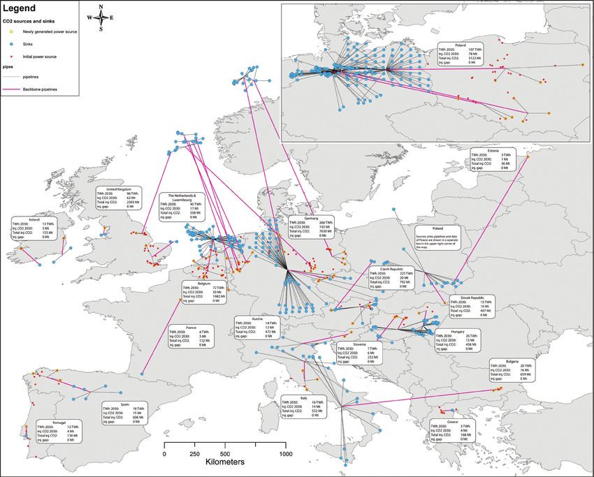
X
EEA Technical report   No 14/2011

        Air pollution impacts from
carbon capture and storage (CCS)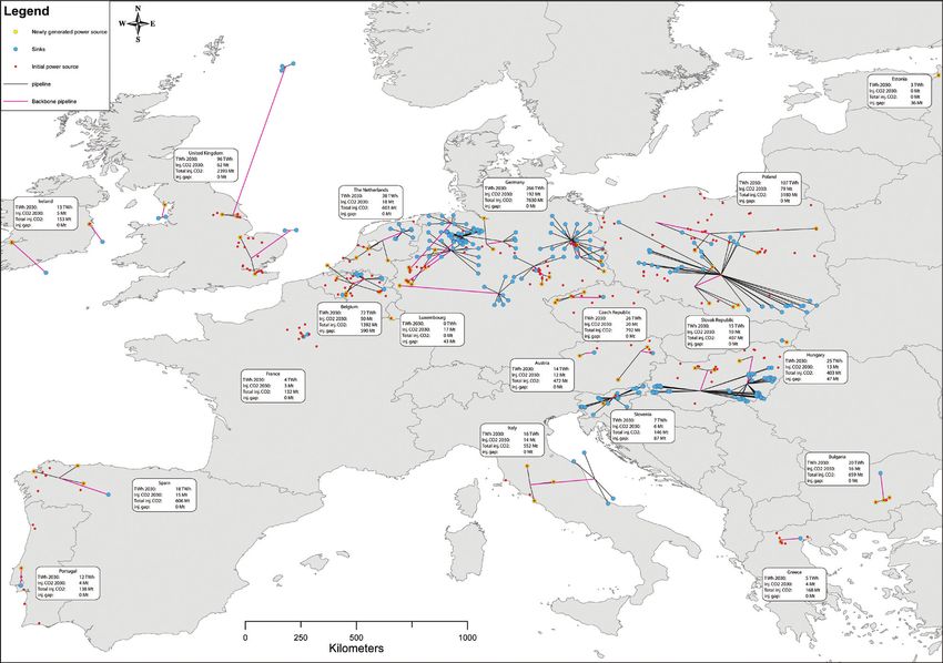
Cover design: EEA
Layout: EEA/Henriette Nilsson

Legal notice
The contents of this publication do not necessarily reflect the official opinions of the European
Commission or other institutions of the European Union. Neither the European Environment Agency
nor any person or company acting on behalf of the Agency is responsible for the use that may be
made of the information contained in this report.

Copyright notice
© EEA, Copenhagen, 2011
Reproduction is authorised, provided the source is acknowledged, save where otherwise stated.

Information about the European Union is available on the Internet. It can be accessed through the
Europa server (www.europa.eu).

Luxembourg: Publications Office of the European Union, 2011

ISBN 978-92-9213-235-4
ISSN 1725-2237
doi:10.2800/84208

European Environment Agency
Kongens Nytorv 6
1050 Copenhagen K
Denmark
Tel.: +45 33 36 71 00
Fax: +45 33 36 71 99
Web: eea.europa.eu
Enquiries: eea.europa.eu/enquiries
Contents

Contents

Acknowledgements..................................................................................................... 4
Executive summary..................................................................................................... 5
1 Introduction......................................................................................................... 12
  1.1 CCS and air pollution — links between greenhouse gas and air pollutant policies.......13
  1.2 Summary of the main CCS processes (capture, transport and storage)
      and life-cycle emission sources...........................................................................14
  1.3 Objectives of this report....................................................................................20

Part A  Review of environmental life‑cycle emissions................................................ 22

2 General considerations......................................................................................... 23
  2.1 General environmental issues — CO2 leakage........................................................23
  2.2 Local health and environmental impacts ..............................................................24
3 Capture technologies ........................................................................................... 25
  3.1 Post-combustion ..............................................................................................26
  3.2 Pre-combustion ...............................................................................................27
  3.3 Oxyfuel combustion .........................................................................................28
4 Transport technologies......................................................................................... 30
  4.1 Pipelines .........................................................................................................30
  4.2 Pipeline construction.........................................................................................30
  4.3 Ships..............................................................................................................31
5 Storage technologies............................................................................................ 32
  5.1 Storage capacity...............................................................................................32
  5.2 Emissions from storage.....................................................................................33
6 Indirect emissions................................................................................................ 35
  6.1 Fuel preparation...............................................................................................35
  6.2 Manufacture of solvents.....................................................................................36
  6.3 Treatment of solvent waste................................................................................36
7 Third order impacts: manufacture of infrastructure.............................................. 37
8 Discussion and review conclusions....................................................................... 38
  8.1 Sensitivity analysis of fuel preparation emissions..................................................39
  8.2 Conclusions......................................................................................................40

Part B  Case study — air pollutant emissions occurring under a future
        CCS implementation scenario in Europe......................................................... 45

9 Case study introduction and objectives................................................................ 46
10 Case study methodology....................................................................................... 47
   10.1 Overview.........................................................................................................47
   10.2 Development of an energy baseline 2010–2050....................................................47
   10.3 Selection of CCS implementation scenarios...........................................................50
   10.4 Determination of the CCS energy penalty and additional fuel requirement................51
   10.5 Emission factors for the calculation of GHG and air pollutant emissions....................53
11 Case study results and conclusions...................................................................... 55
References................................................................................................................ 59
Annex 1  Status of CCS implementation as of June 2011	������������������������������������������ 64

                                             Air pollution impacts from carbon capture and storage (CCS)                        3
Acknowledgements

    Acknowledgements

    This report was compiled by the European              The authors thank Janusz Cofala (International
    Environment Agency (EEA) on the basis of a            Institute for Applied System Analysis, Austria) for
    technical paper prepared by its Topic Centre on Air   his assistance concerning the GAINS model dataset
    and Climate Change (ETC/ACC). The authors of the      together with Hans Eerens (ETC/ACC, PBL – the
    ETC/ACC technical paper were Toon van Harmelen,       Netherlands) for providing the TIMER/IMAGE
    Arjan van Horssen, Magdalena Jozwicka and Tinus       model energy projections for 2050 used in the case
    Pulles (TNO, the Netherlands) and Naser Odeh          study presented in this report.
    (AEA Technology, United Kingdom).

    The EEA project manager was Martin Adams.

4   Air pollution impacts from carbon capture and storage (CCS)
Executive summary

Executive summary

Background                                             technology and in itself should not introduce
                                                       barriers or delays to the EU's overarching objective
Carbon Capture and Storage (CCS) consists of the       of moving toward a lower-energy and more
capture of carbon dioxide (CO2) from power plants      resource-efficient economy. The technology should
and/or CO2-intensive industries such as refineries,    not, for example, serve as an incentive to increase
cement, iron and steel, its subsequent transport       the number of fossil fuel power plants.
to a storage site, and finally its injection into a
suitable underground geological formation for the      In terms of emissions of pollutants, it is well known
purposes of permanent storage. It is considered to     that efforts to control emissions of GHGs or air
be one of the medium term 'bridging technologies'      pollutants in isolation can have either synergistic
in the portfolio of available mitigation actions for   or antagonistic effects on emissions of the other
stabilising concentrations of atmospheric CO2, the     pollutant group, in turn leading to additional
main greenhouse gas (GHG).                             benefits or disadvantages occurring. In the case
                                                       of CCS, the use of CO2 capture technology in
Within the European Union (EU), the European           power plants leads to a general energy penalty
Commission's 2011 communication 'A Roadmap             varying in the order of 15–25 % depending on the
for moving to a competitive low carbon economy in      type of capture technology applied. This energy
2050' lays out a plan for the EU to meet a long‑term   penalty, which offsets the positive effects of CO2
target of reducing domestic GHG emissions by           sequestration, requires the additional consumption
80–95 % by 2050. As well as a high use of renewable    of fuel, and consequently can result in additional
energy, the implementation of CCS technologies in      'direct' emissions (GHG and air pollutant emissions
both the power and industry sectors is foreseen. The   associated with power generation, CO2 capture
deployment of CCS technologies thus is assumed to      and compression, transport and storage) and
play a central role in the future decarbonisation of   'indirect' emissions, including for example the
the European power sector and within industry, and     additional fuel production and transportation
constitutes a key technology to achieve the required   required. Offsetting the negative consequences of
GHG reductions by 2050 in a cost-effective way.        the energy penalty is the positive direct effect of
                                                       CCS technology, which is the (substantial) potential
A future implementation of CCS within Europe,          reduction of CO2 emissions. It is thus important that
however, needs to be seen within the context of the    the potential interactions between CCS technology
wider discussions concerning how Europe may best       implementation and air quality are well understood
move toward a future low-energy, resource-efficient    as plans for a widespread implementation of this
economy. Efforts to improve energy efficiency          technology mature.
are for example one of the core planks of the EU's
Europe 2020 growth strategy and the European
Commission's recent Roadmap to a Resource              Report objectives
Efficient Europe, as it is considered one of the
most cost-effective methods of achieving Europe's      This report comprises two separate complementary
long-term energy and climate goals. Improving          parts that address the links between CCS
energy efficiency also helps address several of the    implementation and its subsequent impacts on GHG
main energy challenges Europe presently faces,         and air pollutant emissions on a life-cycle basis:
i.e. climate change (by reducing emissions of GHGs),
the increasing dependence on imported energy,          Part A discusses and presents key findings from
and the need for competitive and sustainable           the latest literature, focusing upon the potential air
energy sources to ensure access to affordable,         pollution impacts across the CCS life-cycle arising
secure energy. While CCS is therefore regarded as      from the implementation of the main foreseen
one of the technological advances that may help        technologies. Both negative and positive impacts on
the EU achieve its ambitions to decarbonise the        air quality are presently suggested in the literature
electricity‑generating and industrial sectors by       — the basis of scientific knowledge on these issues is
2050, its implementation is considered a bridging      rapidly advancing.

                                        Air pollution impacts from carbon capture and storage (CCS)             5
Executive summary
Part B comprises a case study that quantifies and Potential impacts of CCS implementation
highlights the range of GHG and air pollutant on air pollutant emissions — key findings
life‑cycle emissions that could occur by 2050 under
a low-carbon pathway should CCS be implemented The amount of direct air pollutant emissions
in power plants across the European Union under per unit electricity produced at future industrial
various hypothetical scenarios. A particular focus facilities equipped with CCS will depend to a large
of the study was to quantify the main life-cycle extent on the specific type of capture technology
emissions of the air pollutants taking into account employed. Three potential CO2 capture technologies
the latest knowledge on air pollutant emission were evaluated for which demonstration scale
factors and life-cycle aspects of the CCS life-cycle as plants are expected to be in operation by 2020 —
described in Part A of the report. post-combustion, pre-combustion and oxyfuel
combustion.
Pollutants considered in the report were the main
GHGs CO2, methane (CH4) and nitrous oxide (N2O) Overall, and depending upon the type of CO2
and the main air pollutants with potential to harm capture technology implemented, synergies and
human health and/or the environment — nitrogen trade-offs are expected to occur with respect to the
oxides (NOX), sulphur dioxide (SO2), ammonia emissions of the main air pollutants NOX, NH3,
(NH3), non-methane volatile organic compounds SO2 and PM. For the three capture technologies
(NMVOCs) and particulate matter (PM10). evaluated, emissions of NOX, SO2 and PM will
Figure ES.1 Emission rates of various pollutants for different conversion technologies with and
without CO2 capture
1 400
1 200
1 000
800
600
400
200
nr nr nr nr nr nr nr nr nr nr nr nr nr nr nr nr nr nr nr
0
IGCC NGCC PC GC NGCC PC NGCC PC GC IGCC
no-capture Oxyfuel combustion Post-combustion Pre-combustion
CO2 (g/kWh) NOX (mg/kWh) SO2 (mg/kWh) NH3 (mg/kWh) PM (mg/kWh)
Notes: The indicated values are based on various fuel specifications and are dependent on the configuration and performance of the
power plant and CO2 capture process.
'nr' = not reported; IGCC = Integrated Gasification Combined Cycle; NGCC = Natural Gas Combined Cycle; PC = Pulverised
Coal; GC = Gas Cycle.
Source: Horssen et al., 2009; Koornneef et al., 2010, 2011.
6 Air pollution impacts from carbon capture and storage (CCS)Executive summary
reduce or remain equal per unit of primary energy for coal-based CO2 capture technologies, with
input, compared to emissions at facilities without other indirect sources of emissions including
CO2 capture (Figure ES.1). However, the energy the transport and storage of CO2 contributing
penalty which occurs with CCS operation, and the around 10–12 % to the total;
subsequent additional input of fuel required, may
mean that for some technologies and pollutants a • power generation using natural gas has lower
net increase of emissions per kilowatt-hour (kWh) emissions compared to coal based power
output will result. The largest increase is found for generation, directly as well as indirectly.
the emissions of NOX and NH3; the largest decrease The switching from coal- to gas-fired power
is expected for SO2 emissions. There is at present generation can have larger impacts on the
little available quantitative information on the effect direct and indirect emissions of air pollutants,
of CCS capture technologies on NMVOC emissions. depending on the technologies involved, than
the application of CO2 capture technologies.
In addition to the direct emissions at CCS‑equipped However, in itself, a shift to gas most likely will
facilities, a conclusion of the review is that not be sufficient for the EU to achieve its 2050
the life‑cycle emissions from the CCS chain, goal of reducing domestic GHG emissions by
particularly the additional indirect emissions from 80–95 % and other issues, including energy
fuel production and transportation, may also be security, relative costs, etc., must be taken into
significant in some instances. The magnitude of the consideration.
indirect emissions, for all pollutants, can exceed that
of the direct emissions in certain cases. Emissions It should also be noted that much of the information
from other stages of the CCS life-cycle, such as presently available in the literature concerning
solvent production (for CO2 capture) and its disposal emissions of air pollutants for energy conversion
are considered of less significance, as well as the technologies with CO2 capture is most often based
third order emissions from the manufacturing of on assumptions and not on actual measurements.
infrastructure. As the future CO2 capture technologies move
from laboratory or pilot phase to full-scale
In considering both direct and indirect emissions implementation, a proper quantitative analysis of
together, key findings of the review are: emissions and environmental performance will
be required. At present, much of the available
• increases of direct emissions of NOX and PM are information is merely qualitative in nature which
foreseen to be in the order of the fuel penalty limits the robustness of future studies in this field.
for CCS operation, i.e. the emissions are broadly
proportional to the amount of additional fuel A sound understanding of these synergies and
combusted; trade‑offs between the air pollutants and GHGs is
of course needed to properly inform policymakers.
• direct SO2 emissions tend to decrease since More generally, it is well established that efforts
its removal is a technical requirement for CO2 to control emissions of one group of pollutants in
capture to take place to avoid potential reaction isolation can have either synergistic or sometimes
with amine-based solvents; antagonistic effects on emissions of other pollutants, in
turn leading to additional benefits or disadvantages.
• direct NH3 emissions can increase significantly Examples of these types of trade-offs that can occur
due to the assumed degradation of the between the traditional air pollutants and GHGs are
amine‑based solvent used in post-combustion shown in Figure ES.2. Based on the findings of the
capture technologies; review, CCS technology may be considered to fall into
the upper-right quadrant shown in the figure, i.e. the
• indirect emissions can be significant in technology is considered to be generally beneficial
magnitude, and exceed the direct emissions in both in terms of air quality and climate change.
most cases for all pollutants; However, the potential increase in emissions of certain
air pollutants (e.g. NH3 and also NOX and PM) rather
• the extraction and transport of additional coal means that CCS would not be ranked very high on the
contributes significantly to the indirect emissions 'beneficial for air quality' axis.
Air pollution impacts from carbon capture and storage (CCS) 7Executive summary
Figure ES.2 Air quality (AQ) and climate change (CC) synergies and trade-offs
Beneficial
Beneficial for
for AQ
both AQ
and CC
Energy efficiency
Flue gas desulphurisation Demand management
Vehicle three way catalysts (petrol) Nuclear
Vehicle particulate filters (diesel) Wind, solar, tidal…
Hybrids and low-emission vehicles
Negative Beneficial
for CC for CC
Some conventional biofuels
Energy demand for coal and oil Biomass
fossil fuels in stationary and Combined heat and power
mobile sources Buying overseas carbon credits
Negative
for both AQ Negative
and CC for AQ
Source: Adapted from Defra, 2010.
A case study — air pollutant emissions • a scenario with all coal-fired power plants
occurring under a future CCS implementing CCS, where the additional coal
implementation scenario in Europe (energy penalty) is mined in Australia and
transported to Europe by sea;
The range of potential GHG and air pollutant
life‑cycle emissions that could occur in the year 2050 • a scenario with CCS implemented on all coal-,
should CCS be widely implemented across the EU natural gas- and biomass-fired power plants
under a future low-carbon scenario was assessed, where the additional fuel (energy penalty)
taking into account the latest knowledge on air comes from Europe.
pollutant emission factors and life-cycle aspects of
the CCS chain. These scenarios were selected to assess the
importance of life-cycle emissions with deliberately
Life-cycle emissions for four different hypothetical contrasting assumptions concerning the source (and
scenarios of CCS implementation to power stations hence transport requirements) of the additional
in 2050 were determined (1): required fuel, and across the different fuel types to
which CCS may potentially be applicable. The third
• a scenario without any CCS implementation; scenario involving coal transport from Australia
was, for example, selected to maximise the potential
• a scenario with all coal-fired power plants additional emissions arising from the extra transport
implementing CCS, where the additional coal of fuel required within the CCS life-cycle. The
(energy penalty) is mined in Europe; deployment of CCS in industrial applications has
not been considered.
(1) The CCS scenarios for 2050 were calculated using an energy baseline to 2050 constructed from the PRIMES EU energy forecast to
2030 and extrapolated to 2050 using a low carbon climate mitigation scenario from the TIMER/IMAGE models.
8 Air pollution impacts from carbon capture and storage (CCS)Executive summary
Figure ES.3 shows the modelled 'direct' emissions results are based. The capture of CO2 emissions from
of the various pollutants that occur from the fuel biomass combustion leads to a net removal of CO2
combustion for power generation that occur in from the atmosphere. This of course necessitates the
2050 under the different scenarios. The additional assumption that all biomass is harvested sustainably,
'indirect' emissions from the mining and the and no net changes to carbon stock occur in the
transport of the additional coal, needed because of European or international forests and agriculture
the CCS fuel penalty, are calculated and included in sectors. A main reason for the reduction in SO2 is the
the overall life-cycle results shown in Figure ES.4. requirement within CCS processes to also remove
SO2 from the flue gas prior to the capture and
The life-cycle emissions of both CO2 and SO2 are compression of CO2. This avoids both poisoning the
predicted to decline considerably compared to the CO2 capture solvent and potential system corrosion.
scenario where no implementation of CCS occurs. The transport of additional coal from Australia (or
Implementation of CCS to all coal-, natural gas- indeed any other location) will lead to an increase
and biomass-fuelled power plants also leads to in SO2 emissions from the international shipping
CO2 emissions becoming 'negative' in 2050 under involved to Europe. However, overall, total life‑cycle
this extreme scenario. This is due to the significant SO2 emissions will decrease as the reduction in
increase in biomass use between 2040 and 2050 direct emissions is larger than the increase due to the
according to the energy scenarios upon which the additional shipping.
Figure ES.3 Direct emissions from power generation in 2050 under the different
CCS implementation scenarios
1 200 000
1 000 000
800 000
600 000
400 000
200 000
0
CO2 CH4 N2O NH3 NMVOC NOX PM10 SO2
– 200 000
(Gg) (Mg)
– 400 000
– 600 000
– 800 000
No CCS implemented
Coal-fired powerplants with CCS, coal from Australia
Coal-fired powerplants with CCS, coal from Europe
All coal, gas and biomass, powerplants with CCS
Note: Units in megagrams (Mg), except for CO2 which is expressed in gigagrams (Gg).
Air pollution impacts from carbon capture and storage (CCS) 9Executive summary
Figure ES.4 Direct and indirect emissions (incl. from the mining and transport of fuel) for
the power generation sector in 2050 under the different CCS implementation
scenarios
1 400 000
1 200 000
1 000 000
800 000
600 000
400 000
200 000
0
CO2 CH4 N2O NH3 NMVOC NOX PM10 SO2
– 200 000
(Gg) (Mg)
– 400 000
– 600 000
– 800 000
No CCS implemented
Coal-fired powerplants with CCS, coal from Australia
Coal-fired powerplants with CCS, coal from Europe
All coal, gas and biomass, powerplants with CCS
Note: Units in Mg, except for CO2 which is expressed in Gg.
The overall PM10 emissions for the EU are also biomass-fired power plants. On a life-cycle basis, the
expected to decrease, by around 50 %. The overall NOX emissions are foreseen to increase under
decrease is caused by the low emission factors for the scenario where additional coal is sourced from
CCS‑equipped power plants. Low PM10 emissions Australia due to increased emissions from shipping.
are required for the CO2 capture process in order
not to contaminate the capture solvent. The fuel Ammonia NH3 is the only pollutant for which a
penalty, because of the additional energy needed significant increase in direct emissions compared
for the capture process, will lead to additional to the non-CCS scenario is foreseen to occur. The
PM10 emissions during the coal mining and increase is predicted due to the degradation of
transport stages of the CCS life-cycle, but overall the amine-based solvents that are assumed in the
these increases are smaller in magnitude than the current literature. Nevertheless, compared to the
reduction achieved at the CCS equipped power present-day level of emissions of NH3 from the
plants. EU agricultural sector (around 3.5 million Mg
(tonnes), or 94 % of the EU's total emissions),
The NMVOC and NOX emissions from power the magnitude of the modelled NH3 increase is
plants remain more or less the same after the relatively small. There is also ongoing research into
introduction of CCS, but decrease under the scenario the environmental fate of amine-based solvents (and
of CCS implementation to all coal-, natural gas- and their degradation products, including nitrosamines)
10 Air pollution impacts from carbon capture and storage (CCS)Executive summary
following for example a release from CCS capture of the introduction of CCS in terms of reduced
processes. Nitrosamines and other amine-based emissions of air pollutants could be substantial.
compounds exhibit various toxic effects in the There do remain, however, large uncertainties
environment, and are potential carcinogens, may as to the extent to which CCS technologies will
contaminate drinking water and have adverse actually be implemented in all European countries
effects on aquatic organisms. New solvents are over the coming decades. In addition, as described
under development, with potential to show less earlier, the implementation of CCS should be
degradation. seen as a bridging technology and in itself should
not introduce barriers or delays toward the EU's
In conclusion, it is clear that for the EU as a whole, objectives of moving toward a lower-energy and
and for most Member States, the overall co-benefits more resource‑efficient future economy.
Air pollution impacts from carbon capture and storage (CCS) 11Introduction
1 Introduction
CCS is considered one of the medium-term technologies thus is assumed to play a central role
'bridging' technologies in the portfolio of mitigation in the future decarbonisation of the European power
actions for helping to stabilise atmospheric sector and within industry, and constitutes a key
concentrations of CO2, the main GHG. CCS itself technology to achieve the required GHG reductions
is a term that is commonly applied to a number of by 2050 in a cost-effective way.
different technologies and processes that reduce the
CO2 emissions from human activities. A future implementation of CCS within Europe,
however, comprises just one part of the present
In 2009, the EU agreed to a bundle of specific debate concerning the future direction of European
measures, the so-called EU 'climate and energy' energy policy. It needs also to be considered within
package, to help implement the EU's '20-20-20' the context of the wider discussions concerning
climate and energy targets (2). One of the pieces how Europe may best move toward a low-energy,
of legislation adopted as part of the package was resource-efficient economy with a high share of
Directive 2009/31/EC on the geological storage of renewables, etc. Efforts to improve energy efficiency
CO2, the CCS Directive, which establishes a legal are one of the core planks of the EU's Europe 2020
framework for the environmentally safe geological growth strategy and the European Commission's
storage of CO2 within the EU (European Union, recent Roadmap to a Resource Efficient Europe
2009). The directive covers CO2 storage within (European Commission, 2011b), as it is considered
geological formations in the EU, and lays down one of the most cost-effective methods of achieving
requirements covering the entire lifetime of a Europe's long-term energy and climate goals.
storage site. The Directive's purpose is to ensure the Improving energy efficiency helps address several of
permanent containment of CO2 in such a way as to the main energy challenges Europe presently faces,
prevent and, where this is not possible, eliminate i.e. climate change (through reducing emissions of
as far as possible negative effects and any risk to GHGs), the increasing dependence on imported
the environment and human health. Other specific energy, and the need for competitive and sustainable
aspects are addressed to prevent adverse effects on energy sources to ensure access to affordable, secure
the security of the transport network or storage site, energy (European Commission, 2011c).
and to clarify how CCS shall be considered within
regulatory frameworks. Several guidance documents While CCS can therefore be regarded as one of
to accompany the CCS Directive have also been the technological advances that may help the
published (3). EU achieve its ambitions to decarbonise the
electricity‑generating and industrial sectors by 2050,
The European Commission has recently also at the same time, it should be seen as a bridging
published the communication 'A Roadmap for technology and should not introduce barriers or
moving to a competitive low carbon economy in delays to the EU's overarching objective of moving
2050' (European Commission, 2011a). The 2050 toward a lower-energy and more resource-efficient
Roadmap lays out a plan for the European Union economy The technology should not, for example,
to meet a long-term target of reducing domestic serve as an incentive to increase the number of fossil
GHG emissions by 80–95 % by 2050. As well as a fuel power plants (European Union, 2009). More
high use of renewable energy, the implementation detailed information on the foreseen role of CCS
of CCS technologies into both the power and within the framework of EU policy may be found on
industry sectors is foreseen. The deployment of CCS the website of the European Commission (4).
(2) The EU's '20-20-20' climate and energy targets to be met by the year 2020 comprise:
1. a reduction in EU greenhouse gas emissions of at least 20 % below 1990 levels;
2. twenty per cent of EU energy consumption to come from renewable resources;
3. a 20 % reduction in primary energy use compared with projected levels, to be achieved by improving energy efficiency.
(3) See http://ec.europa.eu/clima/policies/lowcarbon/ccs/implementation/index_en.htm.
(4) See http://ec.europa.eu/clima/policies/lowcarbon/ccs_en.htm.
12 Air pollution impacts from carbon capture and storage (CCS)Introduction
1.1 CCS and air pollution — links It is important to identify, based on the best
between greenhouse gas and air available science and knowledge, those instances
pollutant policies where planned policies and measures may create
additional benefits or disadvantages. In such
Anthropogenic emissions of GHGs and air evaluations, consideration of life-cycle aspects (5)
pollutants occur from the same types of emission can be invaluable in highlighting the intended or
sources, e.g. industrial combustion facilities, vehicle unintended consequences of any policy choice.
exhausts, agriculture, etc. There are therefore many For example, in fossil fuel-based power generation
important interactions between the two thematic systems (both with and without CCS), emissions
areas of climate change and air pollution, not only of air pollutants result not only from the direct
with respect to their sharing the same sources of combustion of the fuel at the industrial facility itself,
pollution but also in terms of the various policy but also indirectly from upstream and downstream
measures undertaken to reduce or mitigate the processes that can occur at different points along a
respective emissions. Often, however, policy life-cycle path.
development and the subsequent development and
implementation of legislation tends to address either Thus, any policy proposal that will affect processes
air pollutants or GHGs. Such instances can occur at a given industrial facility should be informed by
because at the national, regional and/or local scales, knowledge of the potential changes that will also
specific actions are deemed necessary in order to occur along the life-cycle path (in addition to the
help achieve explicit targets for air quality or climate changes that will occur at the facility itself). A sound
change that themselves have been agreed at a higher understanding of the synergies and trade-offs
level, e.g. under national, EU and/or international between air quality and climate change measures
legislation. is needed to properly inform policymakers.
Emissions of CO2 and air pollutants occurring from
Efforts to control emissions of one group of CCS‑equipped facilities are generally considered
pollutants in isolation can have either synergistic or to fall into the upper-right quadrant shown in
sometimes antagonistic effects on emissions of other Figure 1.1, i.e. the technology is considered to be
pollutants, in turn leading to additional benefits beneficial both in terms of air quality and climate
or disadvantages. Simple examples of these types change. However, the situation is often rather
of links that can occur between the traditional air more complex than can be conveyed by such a
pollutants and GHGs include (EEA, 2010) (see also simple categorisation, and more so when life-cycle
Figure 1.1): emissions are taken into account.
• energy efficiency improvements and other Overall, however, implementation of many policies
measures that encourage reducing fossil fuel that address climate change mitigation do lead to
combustion provide general benefits by also positive outcomes for air pollution, and hence can
reducing emissions of air pollutants; lead to considerable additional benefits for human
health and/or the environment. This is clearly seen
• the effect of renewable energy sources may for the European Union's 'climate and energy'
be positive — the availability of wind and package adopted in 2009. The costs of the package
solar energy — or negative — the increased are estimated to be EUR 120 billion per year from
use of biofuels, while nominally CO2 'neutral', 2020 (European Commission, 2008). If the policies
could lead to increased emissions of other air and measures for meeting the package's targets are
pollutants over a life-cycle basis; implemented, the costs of implementing future air
pollution policy in Europe may be reduced by up
• flue gas desulphurisation (FGD) at industrial to EUR 16 billion per year. Factoring air quality into
facilities requires extra energy, leading decisions about how to reach climate change targets,
to additional CO2 emissions, as do some and vice versa, thus can result in policy situations
technologies for reducing vehicle emissions of with greater benefits to society.
air pollutants, etc.
(5) Life-cycle Assessment (LCA) is a commonly used framework to assess the environmental impacts associated with a given product,
process or service across the design, production and disposal stages.
Air pollution impacts from carbon capture and storage (CCS) 13Introduction
Figure 1.1 Air quality (AQ) and climate change (CC) synergies and trade-offs
Beneficial
Beneficial for
for AQ
both AQ
and CC
Energy efficiency
Flue gas desulphurisation Demand management
Vehicle three way catalysts (petrol) Nuclear
Vehicle particulate filters (diesel) Wind, solar, tidal…
Hybrids and low-emission vehicles
Negative Beneficial
for CC for CC
Some conventional biofuels
Energy demand for coal and oil Biomass
fossil fuels in stationary and Combined heat and power
mobile sources Buying overseas carbon credits
Negative
for both AQ Negative
and CC for AQ
Source: Adapted from Defra, 2010.
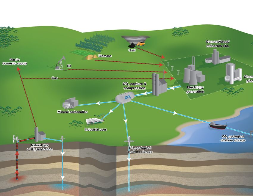
1.2 Summary of the main CCS processes 3. C
O2 storage
(capture, transport and storage) The transported CO2 has to be stored away
and life-cycle emission sources from the atmosphere for a long period. The
rationale behind CCS as a climate change
As noted earlier, CCS is a term that is commonly mitigation measure is that CO2 is not emitted
used to encompass a range of different technological to the atmosphere but can be stored safely and
processes and steps. Three separate stages are effectively permanently underground.
commonly identified within a typical CCS process.
Figure 1.2 presents an overview of possible CCS
1. C
O2 capture systems and shows the three main components of
CCS involves the use of technologies to separate the CCS process: capture, transport and storage
and compress the CO2 produced in industrial and of CO2. Elements of all three components (i.e. CO2
energy-related sources. This process is referred capture, transport and storage) occur in industrial
to as CO2 capture. CO2 needs to be separated and operations today, although mostly not for the
compressed because it is not possible to simply explicit purpose of CO2 storage and not presently
take all of the flue gas from a power plant and on coal-fired power plants at the scale needed for
store it underground. The flue gas has a low wide‑scale mitigation of CO2 emissions (IPCC, 2005).
CO2 content, typically 3–15 % by volume, with
the remainder comprised of nitrogen, steam and The addition of CO2 capture technology to power
small amounts of particles, and other pollutants. plants leads to a general energy penalty which
varies depending on the capture technology
2. C
O2 transport applied. This energy penalty requires additional
The transport of CO2 to a suitable storage consumption of fuel and consequently results in
location. additional direct and indirect emissions. Offsetting
14 Air pollution impacts from carbon capture and storage (CCS)Introduction
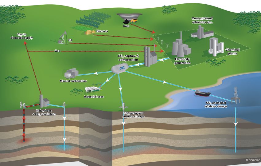
Figure 1.2 Schematic diagram of possible CCS systems showing examples of sources for
which CCS technologies might be relevant, transport of CO2 and storage options
Source: CO2CRC.
the energy penalty is the positive, direct effect of • the 'CO2 chain' encompasses the emissions
CCS technology, which is the (substantial) potential arising from the three main CCS stages
reduction of CO2 emissions. It should further be described previously:
noted that while CO2 capturing from the power plant a) CO2 capture;
has the potential to reduce direct CO2 emissions from b) CO2 compression and transport;
the power plant itself, the indirect CO2 emissions c) CO2 storage.
(and of course air pollutant emissions) upstream and
downstream of the CCS facility cannot be captured, • emissions arising from fuel combustion at the
including the life-cycle emissions associated with the CCS facility including the additional emissions
CO2 transport and storage processes. occurring due to the energy penalty;
It is therefore clear that in assessing the potential • indirect emissions arising from the 'fuel' and
impacts that CCS technologies may have on 'solvent' chains:
emissions of air pollutions, an integrated life-cycle a) fuel preparation including the mining and
type approach is needed in order that the emissions transport of fuel;
occurring away from the actual physical site of CCS b) manufacture of solvents;
capture can also be properly considered. c) treatment of solvent waste.
Potential sources of emissions across the CCS • 'third order' emissions:
life‑cycle stage are illustrated in Figure 1.3, with a a) manufacture of infrastructure.
division made into the separate fuel, solvent and
CO2 chains:
Air pollution impacts from carbon capture and storage (CCS) 15Introduction
Figure 1.3 Potential life-cycle emission sources arising from power generation with CCS
Fuel preparation
Power generation
Solvent Treatment
production CO2 capture of solvent waste
Compression
Third order:
manufacture
of infrastructure
Transport
Storage
Fuel chain Solvent chain CO2 chain Manufacturing
Source: Harmelen et al., 2008.
1.2.1 Capture technologies Box 1.1 provides further explanation of these
technologies; Figure 1.4 shows a schematic diagram
Technologies for the capture of CO2 can potentially of the main capture processes associated with each.
be applied to a range of different types of large
industrial facilities, including those for fossil fuel The idea of CO2 capture is to produce a stream of
or biomass energy production, natural gas refining, pure CO2 gas from a mixture of CO2 and other gas
ethanol production, petrochemical manufacturing, components. All of the shown processes therefore
fossil fuel-based hydrogen production, cement require a step involving the separation of CO2,
production, steel manufacturing, etc. The hydrogen (H2) or O2 from a gas stream. There are
International Energy Agency (IEA) and United many ways to perform this operation: via absorption
Nations Industrial Development Organization or adsorption (separating CO2 by using solvents or
(UNIDO) have recently published a roadmap sorbents for absorption), membranes and thermal
concerning a future pathway to 2050 for the uptake processes such as cryogenic or mineralisation. The
of CCS in industrial applications (IEA/UNIDO, choice of a specific capture technology is determined
2011). largely by the process conditions under which
it must operate. Current post-combustion and
There are four basic systems (6) for capturing CO2 pre‑combustion systems for power plants could
from the use of fossil fuels and/or biomass: capture 80–95 % of the CO2 that is produced. It is
important to stress that CCS is always an 'add‑on'
1. post-combustion; technology. The capture and compression are
2. pre-combustion; considered to need roughly 10–40 % (7) more energy
3. oxyfuel combustion; and than the equivalent plant without capture (IPCC,
4. established industrial processes. 2005).
(6) It is anticipated the first three CO2 capture technologies are likely ready to be demonstrated before 2020 (Harmelen et al., 2008).
(7) Dependent upon the type of the capture and energy conversion technology.
16 Air pollution impacts from carbon capture and storage (CCS)Introduction
Box 1.1 Capture technologies
Post-combustion capture
The CO2 is captured from the flue gas following combustion of the fossil fuel. Post-combustion systems separate CO2
from the flue gases produced by the combustion of the primary fuel in air. These systems normally use a liquid solvent to
capture the small fraction of CO2 (typically 3–15 % by volume) present in a flue gas stream in which the main constituent
is nitrogen (from air). For a modern pulverised coal (PC) power plant or a natural gas combined cycle (NGCC) power plant,
current post-combustion capture systems would typically use an organic solvent such as mono-ethanolamine (MEA) (IEA,
2009a; IPCC, 2005). One advantage of post-combustion systems is that they can be retrofitted (if physical space allows)
to existing coal or gas power plants, industrial facilities, etc. While the technology is considered more mature than the
alternatives of pre-combustion capture and oxyfuel combustion, it has not yet been demonstrated on a large scale.
Pre-combustion capture
Removal of CO2 from the fossil fuel occurs prior to the combustion process. Pre-combustion systems process the primary
fuel in a reactor with steam and air or oxygen to produce a mixture consisting mainly of carbon monoxide (CO) and H2
(synthesis gas — 'syngas'). Additional H2, together with CO2, is produced by reaction of CO with steam in a second reactor
(a 'shift reactor'). The resulting mixture of H2 and CO2 can then be separated into a CO2 gas stream, and a stream of
hydrogen. If the CO2 is stored, the hydrogen is a carbon-free energy carrier that can be combusted to generate power
and/or heat. Although the initial fuel conversion steps are more elaborate and costly, than in post-combustion systems,
the high concentrations of CO2 produced by the shift reactor (typically 15–60 % by volume on a dry basis) and the high
pressures often encountered in these applications are more favourable for CO2 separation. Pre-combustion could for
example be used at power plants that employ integrated gasification combined cycle (IGCC) technology (IEA, 2009a;
IPCC, 2005). The technology is only applicable to new fossil fuel power plants because the capture process requires strong
integration with the combustion process. The technology is expected to develop further over the next 10–20 years and
may be at lower cost and increased efficiency compared to post-combustion.
Oxyfuel combustion capture
Oxyfuel combustion systems use pure oxygen, instead of air for combustion of the primary fuel, to produce a flue gas that
is mainly water vapour and CO2. This results in a flue gas with high CO2 concentrations (more than 80 % by volume). The
water vapour is then removed by cooling and compressing the gas stream. Oxyfuel combustion requires the upstream
separation of oxygen from air, with a purity of 95–99 % oxygen assumed in most current designs. Further treatment
of the flue gas may be needed to remove air pollutants and non-condensed gases (such as nitrogen) from the flue gas
before the CO2 is sent to storage (IEA, 2009a; IPCC, 2005). In theory, the technology is simpler and cheaper than the
more complex absorption process needed in for example the post-combustion CO2 capture process and can achieve high
CO2 removal efficiencies. One disadvantage of the technology is, however, the high present cost of generating pure oxygen
streams.
Capture from industrial processes
CO2 has been captured by industry using various methods since the 1970s to remove CO2 from gas streams where it
is unwanted, or to separate CO2 as a product gas. Examples of the processes include: purification of the natural gas,
production of hydrogen containing synthesis gas for the manufacturing of ammonia, and alcohols and synthesis liquid
fuels. Other CO2-emitting industries are cement, iron and steel production (IPCC, 2005).
Air pollution impacts from carbon capture and storage (CCS) 17Introduction
Figure 1.4 Overview of CO2 capture processes and systems
Source: IPCC, 2005.
1.2.2 Transport option, although transport by ship could be
economically favourable when large quantities have
Except when power plants are located directly above to be transported over long distances (> 1 000 km)
a geological storage site, captured CO2 must be (IPCC, 2005).
transported (onshore or offshore) from the point of
capture to a storage site (injection sink). This is the There is a large network of pipelines for CO2
second step in the CCS chain. The captured CO2 can transport in North America as CO2 has been
be transported as a solid, gas, liquid or supercritical transported there for over 30 years; over
fluid. The desired phase depends on the way how 30 million tonnes (Mt) of CO2 from both natural
the CO2 is transported. and anthropogenic sources are transported per year
through 6 200 km of CO2 pipelines in the United
In general there are two main transport options, via: States of America and Canada (Bellona, 2010; IEA,
2009a and 2009b). Maps showing an indicative
• pipelines and/or future transport and storage network for CO2 across
• shipping. the EU, within and between Member States, are
shown in Figure 1.5.
In theory, it is also possible to transport CO2 by
heavy goods vehicle or rail. However, the very
large number of vehicles and/or rail units that 1.2.3 Storage
would be required to transport millions of tonnes
of CO2 makes the idea impractical. Transport by The third step in the CCS chain is storage of the
heavy goods vehicle would be possible in the initial captured and transported CO2. In the literature three
phases for small research or pilot projects. Hence, main forms of CO2 'storage' are identified (IPCC,
pipelines are considered the only practical option for 2005) (see also Figure 1.2):
onshore transport when CCS becomes commercially
available and millions (or even billions) of tonnes of 1. in deep geological media;
CO2 will be stored annually. Transport by pipeline
is also considered the most generally cost-effective 2. in oceans;
18 Air pollution impacts from carbon capture and storage (CCS)Introduction
3. through surface mineral carbonation (involving In contrast, geological storage of CO2 is a technology
the conversion of CO2 to solid inorganic that can benefit from the experience gained in oil
carbonates using chemical reactions) or in and gas exploration and production. Moreover,
industrial processes (e.g. as a feedstock for this technology seems to offer a large CO2 storage
production of various carbon-containing capacity, albeit unevenly distributed around the
chemicals). globe, and it has retention times of centuries to
millions of years (IPCC, 2005). The injection of CO2
Of these forms, mineral carbonation is very costly in a supercritical state is done via wellbores into
and has a significant adverse environmental suitable geological formations. There are three
impact while ocean storage is as yet considered options for geological CO2 storage (IEA, 2008a and
an immature technology which may endanger 2008b):
ocean organisms and have negative ecosystem
consequences (Bachu et al., 2007; Hangx, 2009; IPCC, 1. deep saline formations;
2005). Both these methods are considered still to 2. depleted oil and gas reservoirs;
be in the research phase (IEA, 2009b; IPCC, 2005). 3. deep non-mineable coal seams.
Further, the EU CCS Directive (European Union,
2009) expressly forbids the storage of CO2 in the Of these, it is expected that saline formations
water column. will provide the opportunity to store the greatest
Figure 1.5 Indicative transport and storage networks for CO2 at a) intra-Member State and
b) EU levels
a)
Source: European Commission, 2008.
Air pollution impacts from carbon capture and storage (CCS) 19Introduction
Figure 1.5 Indicative transport and storage networks for CO2 at a) intra-Member State and
b) EU levels (cont.)
b)
Source: European Commission, 2008.
quantities of CO2, followed by oil and gas reservoirs. This report comprises two separate complementary
Monitoring data from projects worldwide that parts that address the links between CCS and
have involved injection into depleted oil and gas subsequent impacts on GHG and air pollutant
fields and saline formations has shown that the emissions on a life-cycle basis:
CO2 performs as anticipated after injection with no
observable leakage (Bellona, 2010; Hangx, 2009). 1. Part A discusses and presents key findings from
the latest CCS-related literature, focusing upon
the potential air pollution impacts across the
1.3 Objectives of this report CCS life-cycle arising from the implementation
of the main foreseen technologies. Both
To evaluate the potential environmental impact of a negative and positive impacts on air quality
future implementation of CCS then, in addition to are presently suggested in the literature — the
the direct emissions from CCS-equipped facilities, basis of scientific knowledge on these issues
it is clear that the life-cycle emissions from the is rapidly advancing (Koornneef et al., 2011).
CCS chain also need to be considered, particularly The presented data are largely based upon a
the additional indirect emissions arising from fuel literature review, and build upon an earlier
production and transportation. comprehensive set of studies that investigated
20 Air pollution impacts from carbon capture and storage (CCS)Introduction
the impacts of CO2 capture technologies on air pollutants taking into account the latest
transboundary air pollution in the Netherlands knowledge on air pollutant emission factors and
(Harmelen et al., 2008; Horssen et al., 2009). life-cycle aspects of the CCS chain as described
in Part A of the report.
2. Part B comprises a case study that quantifies
and highlights the range of GHG and air Pollutants considered in the literature review and
pollutant life-cycle emissions that could occur accompanying case study were the main GHGs
by 2050 under a low-carbon pathway should CO2, CH4 and N2O and the main air pollutants
CCS be implemented in power plants across the with potential to harm human health and/or the
European Union under various hypothetical environment —NOX, SO2, NH3, NMVOCs and PM10
scenarios. A particular focus of the study was (Box 1.2).
to quantify the main life-cycle emissions of the
Box 1.2 The main air pollutants and their effects on human health and the environment
Nitrogen oxides (NOX)
Nitrogen oxides are emitted during fuel combustion, such as by industrial facilities and the road transport sector. As
with SO2, NOX contribute to acid deposition but also to eutrophication. Of the chemical species that comprise NOX, it is
nitrogen dioxide (NO2) that is associated with adverse effects on health, as high concentrations cause inflammation of the
airways and reduced lung function. NOX also contribute to the formation of secondary inorganic particulate matter and
tropospheric (ground-level) ozone.
Sulphur dioxide (SO2)
Sulphur dioxide is emitted when fuels containing sulphur are burned. It contributes to acid deposition, the impacts of
which can be significant, including adverse effects on aquatic ecosystems in rivers and lakes and damage to forests.
Ammonia (NH3)
Ammonia, like NOX, contributes to both eutrophication and acidification. The vast majority of NH3 emissions — around
94 % in Europe — come from the agricultural sector, from activities such as manure storage, slurry spreading and the use
of synthetic nitrogenous fertilisers. A relatively small amount is also released from various industrial processes.
Non-methane volatile organic compounds (NMVOCs)
NMVOCs, important O3 precursors, are emitted from a large number of sources including industry, paint application, road
transport, dry cleaning and other solvent uses. Certain NMVOC species, such as benzene (C6H6) and 1,3-butadiene, are
directly hazardous to human health. Biogenic NMVOCs are emitted by vegetation, with amounts dependent on the species
and on temperature.
Particulate matter (PM)
In terms of potential to harm human health, PM is one of the most important pollutants as it penetrates into sensitive
regions of the respiratory system. PM is emitted from many sources and is a complex heterogeneous mixture comprising
both primary and secondary PM; primary PM is the fraction of PM that is emitted directly into the atmosphere, whereas
secondary PM forms in the atmosphere following the oxidation and transformation of precursor gases (mainly SO2, NOX,
NH3 and some volatile organic compounds (VOCs)). References to PM in this report refer to primary PM.
Source: EEA, 2010.
Air pollution impacts from carbon capture and storage (CCS) 21Part A
Part A Review of environmental life‑cycle
emissions
Schematic diagram of possible CCS systems showing examples of sources for which CCS technologies might be relevant, transport of
CO2 and storage options
Source: CO2CRC.
22 Air pollution impacts from carbon capture and storage (CCS)General considerations
2 General considerations
2.1 General environmental issues In the event of loss of containment of underground
— CO2 leakage reservoirs, geological and hydrogeological impacts
could result from CO2 storage. These risks will be
CO2 leakage, or the re-emission of transported highly site specific and cannot be assessed without
and stored CO2, is a main concern in relation detailed modelling. In saline reservoirs, injected
to environment and safety associated with CO2 in supercritical phase will be lighter than
implementation of CCS. The actual impacts of brine and vertical migration of leaking CO2 could
any potential leakage will depend upon both the be accompanied by dissolution in shallow aquifer
likelihood of leakages to occur at a given point along waters, forming H2CO3. This could chemically
the CCS chain and of the mass of CO2 released. If the react with and stress the cap-rock material, leading
stored CO2 leaks, the CO2 can harm local terrestrial to changes in geochemistry and hydrogeology.
and marine ecosystems close to the injection point. Storage of CO2 could also possibly be affected by
If very large volumes are released, the CO2 can in regional groundwater flow. In comparison with
theory replace oxygen leading to lethal conditions. depleted oil and gas fields, the characteristics of
For well selected, designed and managed geological which are well understood by their operators, there
storage sites, the Intergovernmental Panel on is a lack of seismic data to accurately map most
Climate Change (IPCC) estimates that risks are saline aquifers. Hydraulic continuity may extend
comparable to those associated with current tens of kilometres away, and at such distances, the
hydrocarbon activities. CO2 could be trapped for probability is high that fractures or fault lines could
millions of years, and although some leakage occurs exist, with possible connection to surface waters
upwards through the soil, well selected storage and underground sources of drinking water. The
sites are considered likely to retain over 99 % of the geological and hydrogeological setting of storage
injected CO2 over 1 000 years. sites will therefore need to be carefully evaluated on
a case-by-case basis to ensure that cumulative and
Thus, the risk of an accidental release from instantaneous releases of CO2 to the environment
geological storage sites is considered relatively would not compromise the effectiveness and safety
small, since the technologies deployed here are of the storage.
well understood and may be controlled, monitored
and fixed on the basis of existing technologies Upon the start of injection, appropriate survey
(IPCC, 2005). It is considered that the primary methods will need to be used at regular intervals to
leakage route will be via the wells or through monitor the movement of the injected CO2 plume, to
the injection pipe rather than via any geological ensure that plume behaviour is as expected and, if
route (Natuurwetenschap en Techniek, 2009). not, to plan remediation options. It is assumed that
It is acknowledged, however, that there is not effective site selection and good regulatory control
yet a complete understanding of the potential of operational practices will ensure an acceptable
mechanisms for possible CO2 migration. Although and understood degree of risk.
the injection pipe is usually protected with
non‑return valves (i.e. to prevent release on a power As noted in the introduction, the EU CCS Directive
outage), there is still a risk that the pipe itself could (European Union, 2009) establishes a legal
tear and leak due to the pressure (IPCC, 2005). framework for the environmentally safe geological
storage of CO2. It covers all CO2 storage within
There are also potential geological and geological formations in the EU, and lays down
hydrogeological impacts of CCS. During pipeline requirements covering the entire lifetime of a storage
operation, large releases of CO2 into the soil from site. The objective of environmentally safe geological
an accidental event could result in formation of storage is to help ensure permanent containment
carbonic acid (H2CO3) via the CO2 being dissolved in of CO2 in such a way as to prevent and, where
soil pore water. There is a small risk that this could this is not possible, eliminate as far as possible
subsequently dissolve any limestone formations negative effects and any risk to the environment
if present in the area, although this would require and human health. Provisions included within
deep penetration and long contact times (see also the Directive concern site selection, monitoring,
Section 2.2 addressing local impacts). corrective measures, CO2 stream acceptance and
Air pollution impacts from carbon capture and storage (CCS) 23You can also read