An Introduction to Robotics - Dr. Bob Williams, Mechanical Engineering, Ohio University EE/ME 4290/5290 Mechanics and Control of ...
←
→
Page content transcription
If your browser does not render page correctly, please read the page content below
An Introduction to Robotics

             Dr. Bob Williams, williar4@ohio.edu

           Mechanical Engineering, Ohio University

EE/ME 4290/5290 Mechanics and Control of Robotic Manipulators

                 © 2019 Dr. Bob Productions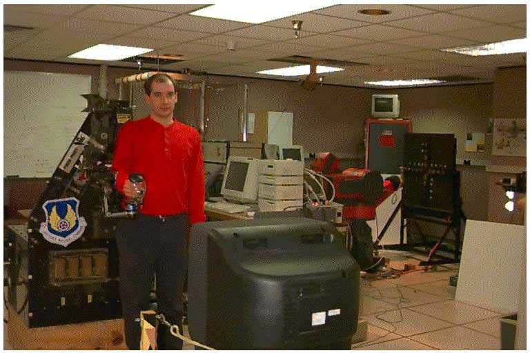
2
                          Introduction to Robotics Table of Contents

BRIEF HISTORY OF ROBOTICS ........................................................................................................ 3

PHOTO GALLERY ................................................................................................................................. 7

DEFINITIONS ........................................................................................................................................ 17

APPLICATIONS .................................................................................................................................... 19

COMMON ROBOT DESIGNS ............................................................................................................. 20

   TRANSLATIONAL ARM DESIGNS .......................................................................................................... 20

   ORIENTATIONAL WRIST DESIGNS ....................................................................................................... 22

   MOBILE ROBOTS .................................................................................................................................. 25

   HUMANOID ROBOTS ............................................................................................................................. 27

   PARALLEL ROBOTS .............................................................................................................................. 28

   CABLE-SUSPENDED ROBOTS ................................................................................................................ 29

   SOFT ROBOTS ....................................................................................................................................... 30

ROBOT PARTS ...................................................................................................................................... 33

TECHNICAL ROBOTICS TERMS ..................................................................................................... 34

ACCURACY, REPEATABILITY, AND PRECISION EXAMPLE ................................................. 35

ROBOT POWER SOURCES/ ACTUATORS ..................................................................................... 37

ROBOT END-EFFECTORS ................................................................................................................. 38

ROBOT CONTROL METHODS ......................................................................................................... 41

ROBOT SENSORS ................................................................................................................................. 43
3
Brief History of Robotics
Leonardo da Vinci created many human-inspired, robot-like sketches, designs, and models in the
1500’s.
Leonardo Humanoid Robot with Internal Mechanisms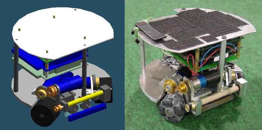
4
The word robot first appeared in print in the 1920 play R.U.R. (Rossum’s Universal Robots) by
Karl Kapek, a Czechoslovakian playwright. Robota is Czechoslovakian for worker or serf
(peasant). Typical of early science fiction, the robots take over and exterminate the human race.
Rossum’s Universal Robots (R.U.R.)
“When he (Young Rossum) took a look at human anatomy he saw immediately that it was too
complex and that a good engineer could simplify it. So he undertook to redesign anatomy, experimenting
with what would lend itself to omission or simplification. Robots have a phenomenal memory. If you
were to read them a twenty-volume encyclopedia they could repeat the contents in order, but they never
think up anything original. They’d make fine university professors.”
– Karel Capek, R.U.R. (Rossum’s Universal Robots), 1920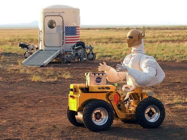
5
Isaac Asimov coined and popularized the term robotics through many science-fiction novels and
short stories. Asimov was a visionary who envisioned in the 1930s a positronic brain for
controlling robots; this pre-dated digital computers by a couple of decades. Unlike earlier robots
in science fiction, robots do not threaten humans since Asimov invented the Three Laws of
Robotics:
1. A robot may not harm a human or, through inaction, allow a human to come to harm.
2. A robot must obey the orders given by human beings, except when such orders conflict
with the First Law.
3. A robot must protect its own existence as long as it does not conflict with the First or
Second Laws.
Asimov Humanoid Robots
“The division between human and robot is perhaps not as significant as that between intelligence
and non-intelligence.”
–R. Daneel Olivaw, The Caves of Steel, Isaac Asimov
6
Joseph Engleberger and George Devoe were the fathers of industrial robots. Their company,
Unimation, built the first industrial robot, the PUMA (Programmable Universal Manipulator Arm,
a later version shown below), in 1961, inspired by the human arm.
PUMA Industrial Robot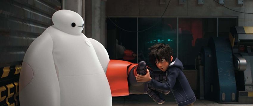
7
Photo Gallery

                       Robonaut and Human Astronaut

                Robonaut on Rover              Human Astronaut on RMS

                     Dextre                    Flight Telerobotic Servicer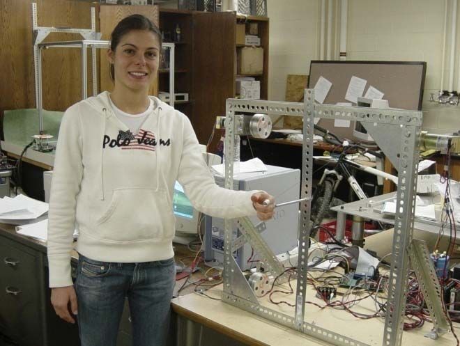
8

           NASA LaRC 8-axis 8R Spatial Serial Manipulator

NASA LaRC 2 6-axis 6R PUMA Robots                   Rosheim Omni Wrist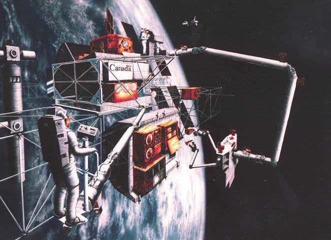
9

                 R2-D2 and C3PO                             NASA JSC Robonaut

                    Stewart-Glapat 5-axis Trailer-Loading Robot

NASA KSC 18-dof Serpentine Truss Manipulator         2 Modules (Rex Kuriger)
10

NASA LaRC 6R PUMA on Stewart Platform       NASA Variable Geometry Truss

                     4-dof GPS/IMU Calibration Platform
11
6-dof 6-PUS Parallel Platform Manipulator 3-dof 3-RPR Parallel Platform Manipulator
6-dof 6-SRU Spatial Parallel Platform Manipulator
with Rosheim Omni-Wrist Actuators12
4-dof Planar Wire-Driven Robot
NIST 6-dof RoboCrane Cable Robot 8-dof Cartesian Contour Crafting Cable Robot13
7-dof Spatial Cable-Suspended Robot Deployable Search and Rescue Cable Robot
3-dof Cable-Suspended Haptic Interface 8-dof Cable-Suspended Haptic Interface
3-dof Omni-Directional RoboCup Wireless Autonomous Mobile Robot14
4-dof Search and Rescue Mobile Robot
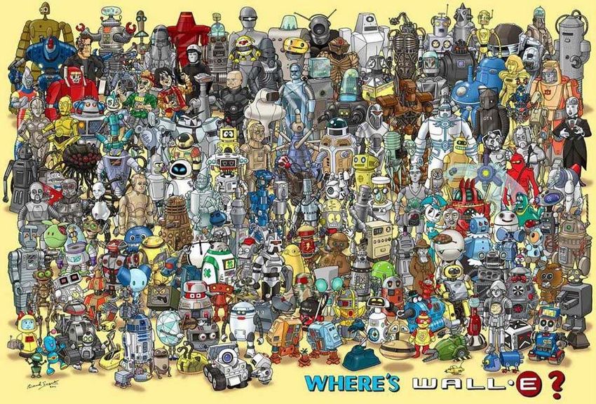
4-dof Autonomous Concrete-Paving Mobile RobotPop-Culture Droids and Humanoid Robots
Famous Pop-Culture Robot Heads/Faces (Daniel Nyari)

T800, Terminator     Astro Boy            Vision, Marvel     Bender, Futurama     Brainiac, DC
                                          Comics                                  Comics
C3P0, Star Wars      Clank, Ratchet and   Cyberman, Doctor   Cylon, Battlestar    Awesome-O 4000,
                     Clank                Who                Galactica            South Park
GORT, The Day the    Rosie, The Jetsons   Alpha, Power       Voltron              EVE, WALL-E
Earth Stood Still                         Rangers
Machine Man,         Optimus Prime,       WALL-E             Wheatley, Portal 2   Marvin, Hitchhikers
Metropolis           Transformers                                                 Guide to the Galaxy
Miles Monroe,        HAL-9000, 2001: A    The Iron Giant     Robby the Robot,     Pneuman, DC
Sleeper              Space Odyssey                           Forbidden Planet     Comics
R2D2, Star Wars      Sentinel, Marvel     ASIMO, Honda       H8, Magnus Robot     Megaman
                     Comics                                  Fighter
17
Definitions
robot An electromechanical device with multiple degrees-of-freedom (dof) that is
programmable to accomplish a variety of tasks.
What are examples of robots?
robotics The science of robots. Humans working in this area are called roboticists.
dof degrees-of-freedom, the number of independent motions a device can make. Also
called mobility.
How many dof does the human arm have? The human leg?
manipulator Electromechanical device capable of interacting with its environment.
anthropomorphic Designed or appearing like human beings.
end-effector The tool, gripper, or other device mounted at the end of a manipulator, for
accomplishing useful tasks.
workspace The volume in space that a robot’s end-effector can reach, both in position and
orientation.18
position The translational (straight-line) location of an object.
orientation The rotational (angular) location of an object. An airplane’s orientation is measured
by roll, pitch, and yaw angles.
pose position and orientation taken together.
link A rigid piece of material connecting joints in a robot.
joint The device which allows relative motion between two links in a robot.
revolute (R) prismatic (P) universal (U) spherical (S)
Common Robot Joint Examples (1, 1, 2, and 3-dof, respectively)
kinematics The study of motion without regard to forces/torques.
dynamics The study of motion with regard to forces/torques.
actuator Provides force/torque for robot motion.
sensor Reads actual variables in robot motion for use in control.
haptics From the Greek, meaning to touch. Haptic interfaces give human operators the
sense of touch and forces from the computer, either in virtual or real, remote
environments. Also called force reflection in telerobotics.19
Applications
Traditionally, robots are applied anywhere one of the 3Ds exist: in any job which is too Dirty,
Dangerous, and/or Dull for a human to perform.
Industry
Industrial robots are used in manufacturing: pick & place, assembly, welding, spray painting,
deburring, machining, etc.
Remote operations
Remote applications for robotics include undersea, nuclear environment, bomb disposal, law
enforcement, and outer space.
NASA Space Shuttle and International Space Station Robots
Service
Service robots have been implemented as hospital helpmates, handicapped assistance, retail,
household servants, vacuum cleaners, and lawnmowers.20
Common Robot Designs
Translational Arm Designs
Cartesian Robot
Cartesian robots have three linear axes of movement (X, Y, Z). They are constructed of three
mutually-orthogonal P joints, with variable lengths L1, L2, L3. Used for pick and place tasks and to move
heavy loads. Also called Gantry Robots, they can trace rectangular volumes in 3D space.
Cylindrical Robot
Cylindrical robot positions are controlled by a variable height L1, an angle 2, and a variable radius
L3 (P joint, R joint, P joint). These robots are commonly used in assembly tasks and can trace concentric
cylinders in 3D space.
Spherical Robot
Spherical robots have two orthogonal rotational R axes, with variables 1 and2, and one P joint,
variable radius L3. The robots’ end-effectors can trace concentric spheres in 3D space.21
SCARA (Selective Compliance Articulated Robot Arm) Robot
SCARA robots have two R joints 1 and2, plus a P joint d3 perpendicular to that plane of motion,
to achieve a 3D xyz workspace. R joint angle 4 is the single-rotation SCARA robot wrist. These are
common table-top assembly robots.
Articulated Robot
Articulated robots resemble the human arm in their 3D motion (they are anthropomorphic). They
have three R joints, with three variable angles 1,2, and3, representing the human body waist, 1-dof
shoulder, and elbow joints. They are versatile robots, but have more difficult kinematics and dynamics
control equations than other serial robots. All of these robot architectures may be used with a variety of
robot wrists to provide the orientation dof. A wrist pitch, with variable angle 4, is also shown with the
articulated robot below.22
Orientational Wrist Designs
The standard robot designs presented in the previous subsection focus on the primary xyz
translational motion for manipulators. Exception: the entire SCARA robot is shown, including its single
wrist roll joint 4.
The current subsection presents some common robot wrist designs to provide primary rotational
motion of the robot end-effector. These are mounted on the end of the 3-dof translational robot arms to
form serial robots with translational and rotational capability.
Note I write ‘primary’ above because the 3 translational joints also cause rotations and also the 3
wrist joints can cause translations of the tool. If the robot wrist design is spherical, i.e. with three joint
axes intersecting in a single point, the translational and rotational motion of the robot may be decoupled
for simpler kinematics equations and control.
SCARA 1-dof roll wrist Mitsubishi 2-dof pitch-roll wrist
Offset 2-dof pitch-yaw wrist for PUMA 3-dof roll-pitch-roll wrist
axisymmetric tasks23
Fanuc S10 offset 3-dof FTS offset 3-dof
roll-pitch-roll wrist pitch-yaw-roll wrist
Human 3-dof yaw-pitch-roll 3-dof Rosheim singularity-free
Wrist pitch-yaw-roll Omni Wrist
The Rosheim Omni Wrist has a singularity-free 3-dof pitch-yaw-roll design. In this case the
rotations all occur independently, i.e. the pitch-yaw-roll order is arbitrary. There are singularities with
this wrist design, but they are designed to lie in the forearm, outside of the joint limits. The Omni Wrist
has a large rotational workspace, with both pitch and yaw axes rotating 90 independently, and the roll
axis with a huge 360 capability. The Omni Wrist can also be equipped with an additional, unlimited
bidirectional roll motion for actuating rotating tools, within the existing wrist.24
VGT 3-dof roll-pitch-yaw parallel wrist OU 3-dof roll-pitch-yaw parallel wrist
AAI ARMII 4-dof roll-yaw-pitch-roll wrist25
Mobile Robots
Mobile robots have wheels, legs, or other means to navigate around the workspace under control.
Mobile robots are applied as hospital helpmates, vacuum cleaners, lawn mowers, among other
possibilities. These robots require good sensors to see the workspace, avoid collisions, and get the job
done. The following six images show Ohio University’s involvement with mobile robots playing soccer,
in the international RoboCup competition (robocup.org).
Early Conceptual Design RoboCup Playing Field; 4 Players and 1 Goalie
RoboCup Player CAD Model RoboCup Player Hardware26 RoboCup Goalie CAD Model RoboCup Goalie Hardware Lawn Mower Robot Vacuum Cleaner Robot
27
Humanoid Robots
         Many young students (and U.S. Senators) expect to see C3PO (from Star Wars) walking around
when visiting a robotics laboratory. Often they are disappointed to learn that the state-of-the-art in robotics
still largely focuses on robot arms. There is much current research work aimed at creating human-like
robots that can walk, talk, think, see, touch, etc. Generally Hollywood and science fiction lead real
technology by at least 20 or 30 years.

               NASA JSC Robonaut                                           Honda Humanoid Robot

               DARwIn-OP 20R 20-dof Humanoid Mobile Walking/Soccer Robot

height          455 mm         (about 18 inches)
mass            2.8 kg         (just over 6 pounds weight)
2-dof pan/tilt head, two 3-dof arms, two 6-dof legs
autonomous and self-contained, on-board sensors, face-down and back-down recovery modes
28
Parallel Robots
Most of the robots discussed so far are serial robot arms, where joints and links are constructed in
a serial fashion from the base, with one path leading out to the end-effector. In contrast, parallel robots
have many arms with active and passive joints and links, supporting the load in parallel. Parallel robots
can handle higher loads with greater accuracy, higher speeds, and lighter robot weight; however, a major
drawback is that the workspace of parallel robots is severely restricted compared to equivalent serial
robots. Parallel robots are used in expensive flight simulators, as machining tools, and can be used for
high-accuracy, high-repeatability, high-precision robotic surgery.
Stewart Platform Parallel Robot Parallel Platform Robot at Ohio University
Delta 3-dof Translational Parallel Robot29
Cable-Suspended Robots
Cable-suspended robots, pictured below, are a special kind of parallel robot where lightweight,
stiff, strong cables are both the actuators and structure for the robot. Though a disadvantage is you cannot
push on a cable (you can apply only tension), cable-suspended robots have large, even huge, translational
workspaces, unlike most parallel robots.
6-dof NIST RoboCrane
7-dof Cable-Suspended Robot Deployable Search and Rescue Cable Robot30
Soft Robots
Soft robots are constructed from highly compliant materials. Often they are developed from a high
degree of biomimicry, such as for octopi and elephant trunks. Their absolute rigidity and accuracy are
very low when compared to traditional rigid robots. However, their safety is inherently very good,
including the ability to work among humans, and envelop objects for grasping them. Often they are
actuated by air (or other fluid) pressure and/or artificial muscles, which are generally much more difficult
to control than those of traditional robots.
Octopus-Inspired Soft Robot (Quadrapus?)
https://i.ytimg.com/vi/A7AFsk40NGE/maxresdefault.jpg
Elephant-Trunk-Inspired Soft Robot
https://3c1703fe8d.site.internapcdn.net/newman/gfx/news/hires/roboticarmsh.jpg
In a twist on history (where Hollywood often leads technology by decades), the soft robot Baymax
in the film Big Hero 6 was strongly inspired by work in the CMU Soft Robotics Lab.31
Soft Robot Baymax from Big Hero 6
https://thetartan-assets.s3.amazonaws.com/uploads/35508/original/14252631454_341fb04d8c_o.jpg
The Venn diagram1 below relates hard vs. soft, discrete vs. continuous, and non-redundant vs.
redundant vs. hyper-redundant (kinematic redundancy) robots. Then the ensuing table1 presents
characteristics, properties, capabilities, and design of rigid vs. discrete hyper-redundant vs. hard
continuous vs. soft robots.
Hard vs. Soft Robots Venn Diagram
Trivedi et al., 2008
1
D. Trivedi, C.D. Rahn, W.M. Kierb, and I.D. Walker, 2008, Soft robotics: Biological inspiration, state of the art, and future
research, Applied Bionics and Biomechanics, 5(3): 99–117.32
Hard vs. Soft Robots Characteristics
Trivedi et al., 200833
Robot Parts
base
shoulder
elbow
wrist
tool-plate
end-effectors (not shown)34
Technical Robotics Terms
Speed
Speed is the amount of distance per unit time at which the robot can move, usually specified in
inches per second or meters per second. The speed is usually specified at a specific load or assuming that
the robot is carrying a fixed weight. Actual speed may vary depending upon the weight carried by the
robot.
Load Bearing Capacity
Load bearing capacity is the maximum weight-carrying capacity of the robot. Serial robots that
carry large weights, but must still be precise, are heavy and expensive, with poor (low) payload-to-weight
ratios.
Accuracy
Accuracy is the ability of a robot to go to the specified position without making a mistake. It is
impossible to position a machine exactly. Accuracy is therefore defined as the ability of the robot to
position itself to the desired location with the minimal error (usually 0.001 inch).
Repeatability
Repeatability is the ability of a robot to repeatedly position itself when asked to perform a task
multiple times. Accuracy is an absolute concept, repeatability is relative. Note that a robot that is
repeatable may not be very accurate. Likewise, an accurate robot may not be repeatable.
Precision
Precision is the ‘fineness’ with which a sensor can report a value. For example, a sensor that reads
2.1178 is more precise than a sensor that reads 2.1 for the same physical variable. Precision is related to
significant figures. The number of significant figures is limited to the least precise number in a system of
sensing or string of calculations.35
Accuracy, Repeatability, and Precision Example
The concepts of accuracy, repeatability, and precision were defined on the previous page. These
terms, all meaning quite different things, are very important in robotics. I find common English usage
obscures these terms. For instance many people say precise when they mean accurate. Therefore a
specific example may be warranted to further clear up these definitions.
This example came from real-world experience. Three days in a row I bicycled the exact same
route to and from work and I was amazed that my bike computer recorded the following data.
day distance (km) time (hrs:min:sec)
day 1 15.06 0:45:17
day 2 15.06 0:45:19
day 3 15.06 0:45:18
Are these three rides accurate, repeatable, or precise?
Answer: this amazing data is highly repeatable, since the distance and time turned out nearly
identical for three separate cycling instances of the same route.
Is this data accurate? To answer this, we need to know the true measure of distance. If we knew
the exact distance to be 15.10 km, then we would say the data is quite accurate. Conversely if the true
value were 16.22 km, we would say the data is not especially accurate and we would need to recalibrate
the distance measurement of the computer. I cannot know the true distance without a lot of time and
expense, so I am forced to rely on my previous calibration of the computer, using mile-marks on the bike
path, for accuracy.
Usually the time measurement in a bike computer should be highly accurate, but with automatic
starting and stopping of time measurement with bike motion, there could be some daily variations (that
did not show up much in this data, evidently).
Is this data precise? The answer to this question is relative. The distance measurement of 15.06
is more precise than another computer that would measure 15.1 and less precise than yet another computer
that would measure 15.063. The time measurement of 0:45.17 is more precise than another computer that
would measure 0:45 and less precise than yet another computer that would measure 0:45:17.6.
Certainly the precision of my bike computer, to the nearest hundredth of a km and to the nearest
second, is plenty precise for everyday cycling.36
Work Envelope
Work envelope is the maximum robot reach, or volume within which a robot can operate. This is
usually specified as a combination of the limits of each of the robot's parts. The figure below shows how
a work-envelope of a robot is documented. This is also called Robot Workspace
Workcells
Robots seldom function in an isolated environment. In order to do useful work, robots must
coordinate their movements with other machines and equipment, and possibly with humans. A group of
machines/equipment positioned with a robot or robots to do useful work is termed a workcell. For
example, a robot doing welding on an automotive assembly line must coordinate with a conveyor that is
moving the car-frame and a laser-positioning / inspection robot that uses a laser beam to locate the position
of the weld and then inspect the quality of the weld when it is complete.37
Robot Power Sources/ Actuators
The robot drive system and power source determine characteristics such as speed, load-bearing
capacity, accuracy, and repeatability as defined above.
Electric motors (DC servomotors)
A robot with an electrical drive uses electric motors to position the robot. These robots can be
accurate, but are limited in their load-bearing capacity.
Hydraulic cylinders (fluid pressure)
A robot with a hydraulic drive system is designed to carry very heavy objects, but may not be very
accurate.
Pneumatic cylinders (air pressure)
A pneumatically-driven robot is similar to one with a hydraulic drive system; it can carry less
weight, but is more compliant (less rigid to disturbing forces).
McKibben Artificial Muscles (air pressure)
The McKibben artificial muscle was invented in the 1950’s, but was too complicated to control
until the 1990’s (computers and nonlinear controls technology have greatly improved). Like the human
muscle, these artificial muscles can only contract, and cannot push. They have natural compliance and a
very high payload-to-weight ratio.
McKibben Muscle Human Arm Model with McKibben Muscles
Piezoelectric materials
A piezoelectric material can be used as an actuator since it deflects when a voltage is applied.
These are not very useful in robotics since the motion and forces are so small. Conversely, a piezoelectric
material may be used as a sensor, reading the resulting voltage when the material is deflected by outside
forces.38
Robot End-Effectors
End-effectors are the tools attached to the end of the robot arm that enable it to do useful work.
Most robot manufacturers either do not include end-effectors with their robots or include a general-
purpose gripper to allow you to do simple tasks. Typically, the end-effectors must be purchased or
designed separately. Also called end-of-arm-tooling, end-effectors are usually attached to the robot tool
plate (after the last wrist joint) via a standard mechanical interface. Like robots themselves, end-effectors
require a power source, often electric or pneumatic.
Grippers
Grippers are the most common end-effectors. They provide the equivalent of a thumb and an
opposing finger, allowing the robot to grasp small parts and manipulate them.
Parallel-Jaw Gripper Versatile Planar Gripper Suction-Cups Gripper
3-fingered Gripper 4-fingered Gripper Humanoid Robot Hand
Fingerless Gripper39
Machine Tools
Robot end-effectors can also be machine tools such as drills, grinding wheels, cutting wheels and
sanders.
Drill Tool NASA Cutter/Scoop Robot Measuring System
Measuring Instruments
Measuring instruments are end-effectors that allow the robot to precisely measure parts by running
the arm lightly over the part using a measuring probe or gauge.
Laser and Water Jet Cutters
Laser and water jet cutters are robot end-effectors that use high-intensity laser beams or high-
pressure abrasive water jets to cut sheet metal or fiberglass parts to shape.
Laser-beam Tool Welding Torch Spray-Painting Robots
Welding Torches
Welding torches are robot end-effectors that enable robots to weld parts together. These end-
effectors are widely used in the automotive industry.
Spray Painting Tools
Automatic spray painting is a useful application for robots, in the automotive and other industries.40
Glue Application Tools
Automatic spot or trajectory gluing is a useful application for robots, in the automotive and other
industries.
Glue-Applying Robot Robot Tool Changer
Tool Changers
Some robot systems are equipped with automatic tool changers to extend the usefulness of the
robot to more tasks.41
Robot Control Methods
All robot control methods involve a computer, robot, and sensors.
Lead-Through Programming
The human operator physically grabs the end-effector and shows the robot exactly what motions
to make for a task, while the computer memorizes the motions (memorizing the joint positions, lengths
and/or angles, to be played back during task execution).
Teach Programming
Move robot to required task positions via teach pendant; computer memorizes these configurations
and plays them back in robot motion sequence. The teach pendant is a controller box that allows the
human operator to position the robot by manipulating the buttons on the box. This type of control is
adequate for simple, non-intelligent tasks.
Microbot with Teach Pendant
Off-Line Programming
Off-line programming is the use of computer software with realistic graphics to plan and program
motions without the use of robot hardware (such as IGRIP).42
Autonomous
Autonomous robots are controlled by computer, with sensor feedback, without human
intervention. Computer control is required for intelligent robot control. In this type of control, the
computer may send the robot pre-programmed positions and even manipulate the speed and direction of
the robot as it moves, based on sensor feedback. The computer can also communicate with other devices
to help guide the robot through its tasks.
Teleoperation
Teleoperation is human-directed motion, via a joystick. Special joysticks that allow the human
operator to feel what the robot feels are called haptic interfaces.
Force-Reflecting Teleoperation System at Wright-Patterson AFB
Telerobotic
Telerobotic control is a combination of autonomous and teleoperation control of robot systems.43
Robot Sensors
Robots under computer control interact with a variety of sensors, which are small electronic or
electro-mechanical components that allow the robot to react to its environment. Some common sensors
are described below.
Vision
A vision system has a computer-controlled camera that allows the robot to see its environment and
adjust its motion accordingly. Used commonly in electronics assembly to place expensive circuit chips
accurately through holes in the circuit boards. Note that the camera is actually under computer control and
the computer sends the signals to the robot based upon what it sees.
Voice
Voice systems allow the control of the robots using voice commands. This is useful in training
robots when the trainer has to manipulate other objects.
Tactile
Tactile sensors provide the robot with the ability to touch and feel. These sensors are used for
measuring applications and interacting gently with the environment.
Force/Pressure
Force/pressure sensors provide the robot with a sense of the force being applied on the arm and
the direction of the force. These sensors are used to help the robot auto-correct for misalignments, or to
sense the distribution of loads on irregular geometry. Can also measure torques, or moments, which are
forces acting through a distance. Can be used in conjunction with haptic interfaces to allow the human
operator to feel what the robot is exerting on the environment during teleoperation tasks.
Proximity
Proximity sensors allow the robots to detect the presence of objects that are very close to the arm
before the arm actually contacts the objects. These sensors are used to provide the robot with a method of
collision avoidance.
Limit Switches
Limit switches may be installed at end-of-motion areas in the workspace to automatically stop the
robot or reverse its direction when a move out-of-bounds is attempted; again, used to avoid collisions.
Other Sensors
encoder measures angle
potentiometer measures angle or length
LVDT measures length (linear variable displacement transducer)
strain gauge measures deflection
ultrasonic sensor measures distance
infrared sensor measures distance
light sensor detects presenceYou can also read