AN0003: UART Bootloader - Silicon Labs
←
→
Page content transcription
If your browser does not render page correctly, please read the page content below

AN0003: UART Bootloader

This application note is intended for users of the EFM32 UART
bootloaders. The bootloader enables users to program the                                   KEY POINTS

EFM32 Series 0, EZR32 Series 0, and EFM32 Series 1 devices                                 • All EFM32 devices are pre-programmed
through a UART without the need for a debugger.                                              with the bootloader, which:
                                                                                             • Can remain alongside customer
In addition to booting user applications, the EFM32/EZR32 bootloader offers a destruc-          applications to support field upgrades.
tive write mode, which allows the user to overwrite the bootloader so that the entire        • Can be overwritten to maximize
flash space can be used for user applications. In the EFM32 Series 1 devices, the              available flash area (EFM32 Series 0
bootloader resides in the reserved area of flash memory, and as such, the bootloader           and EZR32 Series 0 only) or be
for these devices offers no destructive write mode. There is, however, a bit in the lock       disabled by a lock bit in the lock bit
bit page that can be set to disable the bootloader in the EFM32 Series 1 devices.              page (EFM32 Series 1 only).
                                                                                             • Communicates using an UART interface
In all devices, the contents of the flash can be verified through a CRC checksum and           (See section 1.2 for part-specific
debug lock can be enabled to protect IP. Because the bootloader uses the established           peripheral configuration and supported
XMODEM-CRC protocol for data upload, any serial terminal program can be used to                baudrates).
communicate with the bootloader.                                                             • Supports single-character commands
                                                                                               to: program (upload/overwrite), verify
This application note includes the following:                                                  (calculate checksums), secure (write-
 • This PDF document                                                                           protect, lock the debug port), etc. the
                                                                                               EFM32 device.
 • Source files (zip)
                                                                                             • Accepts file transfers using the
    • Full bootloader source code                                                              XMODEM-CRC protocol.
    • IAR EW project files                                                                   • Is invoked after a reset while
 • IAR linker files for applications                                                           DBG_SWCLK is pulled high.

 • Binary images of the bootloader

silabs.com | Building a more connected world.                                                                                     Rev. 1.76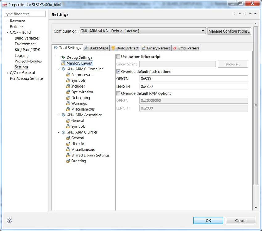
AN0003: UART Bootloader
                                                                                                                   Device Compatibility

1. Device Compatibility

This application note supports multiple device families, and some functionality is different depending on the device.

The UART bootloader is preprogrammed in all EFM32 Series 0, all EZR32 Series 0, and some EFM32 Series 1 devices. EFM32 Series
0 and EZR32 Series 0 devices which have the USB peripheral also include a USB bootloader. The bootloader for USB enabled devices
is covered in application note AN0042: USB UART Bootloader, available through Simplicity Studio (www.silabs.com/simplicity) or from
the Silicon Labs website at www.silabs.com.

Here is a list of the devices supported:

EFM32 Series 0:
 • EFM32 Gecko (EFM32G)
 • EFM32 Giant Gecko (EFM32GG)
 • EFM32 Wonder Gecko (EFM32WG)
 • EFM32 Leopard Gecko (EFM32LG)
 • EFM32 Tiny Gecko (EFM32TG)
 • EFM32 Zero Gecko (EFM32ZG)
 • EFM32 Happy Gecko (EFM32HG)

EZR32 Series 0:
 • EZR32 Wonder Gecko (EZR32WG)
 • EZR32 Leopard Gecko (EZR32LG)
 • EZR32 Happy Gecko (EZR32HG)

EFM32 Series 1:
 • EFM32 Pearl Gecko (EFM32PG1/EFM32PG12 Rev C onwards)
 • EFM32 Jade Gecko (EFM32JG1/EFM32JG12 Rev C onwards)
 • EFM32 Giant Gecko GG11 (EFM32GG11)
 • EFM32 Tiny Gecko 11 (EFM32TG11)

Note: IOVDD should not be supplied from the DC-DC converter on EFM32xG11/12 devices. At reset, the DC-DC converter defaults to
an unconfigured safe state with its output floating such that connected circuits remain unpowered until firmware performs the necessary
configuration. Fresh from the factory, a blank device will run the bootloader and fail in its attempt to communicate with a host via the
BOOT_RX and BOOT_TX pins without IOVDD power. Use of the debug interface (DBG_SWCLKTCK and DBG_SWDIOTMS) for initial
firmware download would, in this case, be similarly fruitless.

Note: This bootloader software does not support voltage scaling on EFM32 Series 1.

EFR32 Series 1 (EFR32xG1/EFR32xG12/EFR32xG13/EFR32xG14) devices are not supported by this bootloader. The bootloader for
these devices is included in the protocol stack software. These devices include:
 • EFR32 Blue Gecko (EFR32BGxx)
 • EFR32 Flex Gecko (EFR32FGxx)
 • EFR32 Mighty Gecko (EFR32MGxx)

silabs.com | Building a more connected world.                                                                               Rev. 1.76 | 2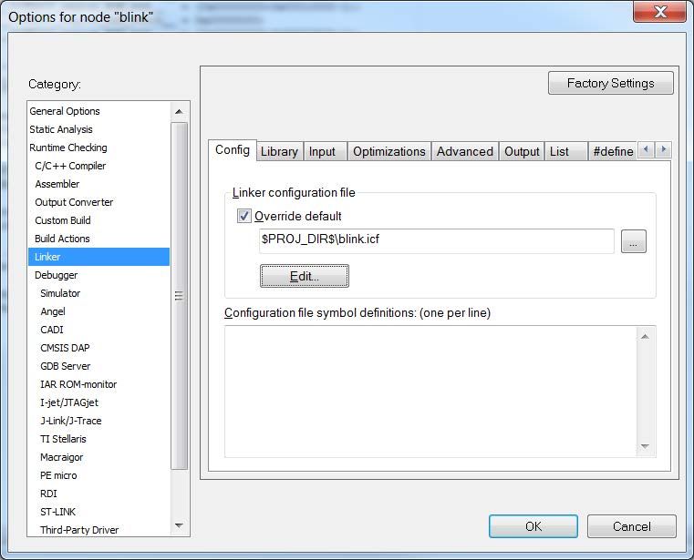
AN0003: UART Bootloader
                                                                                                        Starting the UART Bootloader

2. Starting the UART Bootloader

2.1 Entering Bootloader Mode

To enter bootloader mode, DBG_SWCLK must be pulled high and the EFM32 Series 0, EZR32 Series 0, or EFM32 Series 1 device
must be reset. If DBG_SWCLK is low on reset, the bootloader will check the application space in flash. If the application space contains
a valid application and DBG_SWCLK is low, the bootloader will run that application. If there is not a valid application present, the boot-
loader will sleep in EM2 to conserve power, while periodically checking the bootloader pins.

Note: DBG_SWCLK has an internal pull-down. Leaving this pin unconnected will not invoke bootloader mode on reset.

Note: Earlier revisions of the bootloader used both DBG_SWDIO and DBG_SWCLK pins to enter the bootloader. You can still enter the
bootloader by pulling the DBG_SWDIO line low, but debug locking will not work.

2.2 Initializing Communication with the UART Bootloader

For the EFM32 Series 0 and EZR32 Series 0 devices, the UART bootloader generally uses GPIO pins PE11 (RX) and PE10 (TX) for
UART communication (see note below for exceptions). Consult the device specific data sheet for pin locations.

Note: For EFM32G, EFM32GG, EFM32LG, and most EFM32TG parts, the bootloader communicates using USART0 in Location 0.
However, some devices do not have a USART0 peripheral, and others do but don't have a Location 0 option. For these and other rea-
sons, the bootloaders in EFM32ZG, EFM32HG, and some EFM32TG (specifically EFM32TG108Fxx and EFM32TG110Fxx) parts all
use LEUART0, location 3. Note that this location overlaps the regular SWD port, which, as discussed above, is used to enter the boot-
loader. Therefore, when using these parts, you should use a 4 kΩ pull-up on DBG_SWCLK. For the EFM32 Series 1 devices, the boot-
loader uses the USART connection on port F0 (DBG_SWCLK) and F1 (DBG_SWDIO). These devices should also use a 4 kΩ pull-up
on DBG_SWCLK.

The UART uses 1 stop bit, no parity, and 8 data bits. In addition, the bootloader uses autobaud to enable a wide variety of different
terminals. The autobaud functionality senses the baudrate used by the terminal program and adjusts accordingly. This initialization
done by sending one uppercase "U" to the bootloader immediately after opening a serial connection to the device. The bootloader
senses the timing between bits and adjusts its own prescaler to match the sensed baudrate. Navigate to [an0003_efm32_uart_boot-
loader]>[binaries]>[notes.txt] in the AN0003 software package (available here - https://www.silabs.com/support/resources) for a part-
specific range of baud rates compatible with the autobaud algorithm.

silabs.com | Building a more connected world.                                                                                Rev. 1.76 | 3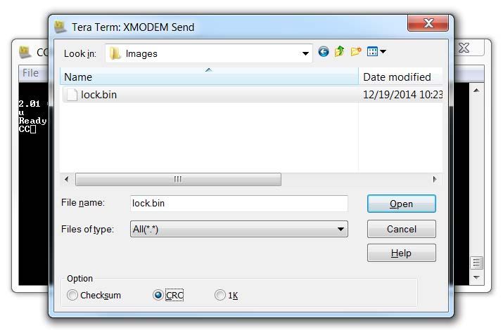
AN0003: UART Bootloader
                                                                                                         Starting the UART Bootloader

                      Figure 2.1. Configuring the serial port for UART bootloader in Tera Term on Windows 7

Once the bootloader has been successfully initialized it will print the bootloader version and chip unique ID:

1.40 ChipID: F08AB6000B153525

Note: Bootloader versions prior to version 1.40 do not print the bootloader version, only the chip unique ID.

Note: Navigate to [an0003_efm32_uart_bootloader]>[binaries]>[bootloader-matrix.txt] in the AN0003 software package (available
here - https://www.silabs.com/support/resources) for the latest version of the Bootloader per family.

silabs.com | Building a more connected world.                                                                               Rev. 1.76 | 4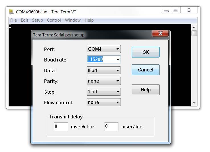
AN0003: UART Bootloader
                                                                                                          Starting the UART Bootloader

2.3 Command Line Interface

The command line interface uses single letter characters as commands. The following are the single, lower-case letters character com-
mands that are supported by Command Line Interface :
u

    Upload application.

    EFM32 Series 0 and EZR32 Series 0: This command lets the user upload an application to the flash, while keeping the bootloader
    intact. For an application to work correctly, it must use a linker file which places the application start address at 0x800 for EFM32G,
    EFM32TG, EFM32ZG and EFM32HG parts and at 0x1000 for EFM32GG, EFM32LG and EFM32WG parts. The application is transfer-
    red using the XMODEM-CRC protocol.

    EFM32 Series 1: This command lets the user upload an application to the flash. No special modification to the user application is
    necessary because the bootloader resides in reserved flash and cannot be overwritten. The application is transferred using the XMO-
    DEM-CRC protocol.
d

    Destructive upload (EFM32 Series 0 and EZR32 Series 0 only). This command lets the user upload an application to flash, overwriting
    the bootloader. No modification of the start address of the user application is necessary. The application is transferred using the XMO-
    DEM-CRC protocol. Destructive upload is not an option on the EFM32 Series 1 devices.
t

    Upload to user page. This command lets the user write to the user information page. The data is uploaded using the XMODEM-CRC
    protocol.
p

    Upload to lock page. This command lets the user write to the lock bits information page. The data is uploaded using the XMODEM-
    CRC protocol.
b

    Boot application. This command will start the uploaded application.
l

    Debug lock. This command sets the debug lock bit in the lock page. The EFM32 Series 0, EZR32 Series 0, or EFM32 Series 1 will be
    locked for debugging.
v

    Verify flash checksum. This command calculates the CRC-16 checksum of the entire flash and prints it. This is suitable for use in
    conjunction with the [d] command (EFM32 Series 0 and EZR32 Series 0) or the [u] command (EFM32 Series 1). Please note that the
    [v] command and the [c] command will yield the same result on the EFM32 Series 1 devices.
c

    Verify application checksum. This command calculates the CRC-16 checksum of the application and prints it. This is suitable for use in
    conjunction with the [u] command.
    Please note that the [c] command and the [v] command will yield the same result on the EFM32 Series 1 devices.
n

    Verify user page checksum. This command calculates the CRC-16 checksum of the user page and prints it. This is suitable for use in
    conjunction with the [t] command.
m

    Verify lock page checksum. This command calculates the CRC-16 checksum of the lock page and prints it. This is suitable for use in
    conjunction with the [p] command.
r

    Reset the EFM32 Series 0, EZR32 Series 0, or EFM32 Series 1 device.

silabs.com | Building a more connected world.                                                                                  Rev. 1.76 | 5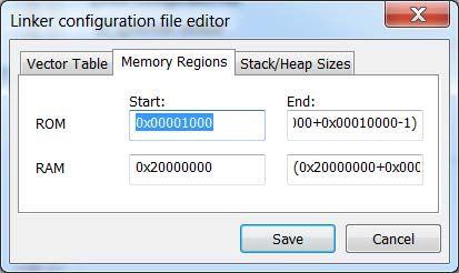
AN0003: UART Bootloader
                                                                                                           Uploading Applications

3. Uploading Applications

To upload an application to the EFM32 Series 0, EZR32 Series 0, and EFM32 Series 1, either the [u] (all devices) or [d] (EFM32 Series
0 and EZR32 Series 0 only) command must be used. After pressing the key, use the terminal software built-in support for XMODEM-
CRC to transfer the file. Any terminal software may be used, as long as it supports XMODEM-CRC transfers.

To send a file through XMODEM-CRC in Tera Term, navigate to [File]>[Transfer]>[XMODEM]>[Send...]. The figure below shows an
example of transferring a file using the built in transfer support in Tera Term.

                                  Figure 3.1. Transferring a File using XMODEM-CRC with Tera Term

silabs.com | Building a more connected world.                                                                           Rev. 1.76 | 6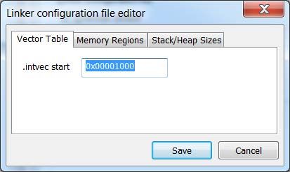
AN0003: UART Bootloader
                                                                                                                  Uploading Applications

3.1 Creating Applications for Use with the Bootloader - EFM32 Series 0 and EZR32 Series 0

Note: For information on creating applications for use with the EFM32 Series 1 devices, see 3.2 Creating Applications for Use with the
Bootloader - EFM32 Series 1.

There are two possibilities when uploading applications using the bootloader for EFM32 Series 0 and EZR32 Series 0 devices: destruc-
tive and regular upload. Destructive upload will overwrite the bootloader. No additional steps are required for creating applications in
this case. Regular uploading keeps the bootloader. This allows future upgrades using the bootloader. However, the applications must
be prepared for this to work. For applications to work with the bootloader, they must be created with a starting address of 0x800 for
EFM32G, EFM32TG, EFM32ZG and EFM32HG parts, and at 0x1000 for EFM32GG, EFM32LG and EFM32WG parts. The reason for
this is that the bootloader itself occupies flash area between 0x0 and 0x7FF or 0x0FFF, respectively. For an application to coexist with
the bootloader, the application linker file must be changed from the default flash start address of 0x0.

Note:

If you need to debug your application while using one of these linker files, you must explicitly set the position of the vector table in your
code. This can be done with:

SCB->VTOR=0x800; // EFM32G, EFM32TG, EFM32ZG and EFM32HG parts

or

SCB->VTOR=0x1000; // EFM32GG, EFM32LG and EFM32WG parts

In the released application this is not necessary as VTOR is set by the bootloader itself, before starting the application. See Boot.c for
details.

silabs.com | Building a more connected world.                                                                                   Rev. 1.76 | 7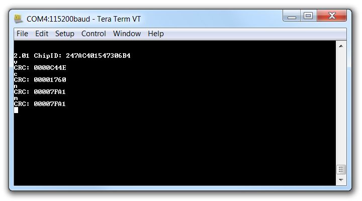
AN0003: UART Bootloader
                                                                                                                 Uploading Applications

3.1.1 Creating an Application with IAR

To create an application using IAR, navigate to [an0003_efm32_usb_uart_bootloader]>[iar_linker_files] in the AN0003 software
package (available here - https://www.silabs.com/support/resources) and use the part-specific linker files for your project. This will set
up the correct starting address for the binary. Another option is to right-click on the IAR project and Select [Options..]. Navigate to the
[Linker] tab and ensure that the [Override default] option is checked.

                                                    Figure 3.2. IAR Project Options

Create an .icf file within the Project Directory and click [Edit]. Set the starting address of the Vector Table in the [Vector Table] tab to
[0x0800] or [0x1000] depending on the part. Change the starting address of ROM in the [Memory Regions] tab to [0x0800] or [0x1000]
depending on the part. Click [Save] when done. Click [OK] in the [Options] window.

                                                Figure 3.3. Change Vector Table Address

silabs.com | Building a more connected world.                                                                                  Rev. 1.76 | 8
AN0003: UART Bootloader
Uploading Applications
Figure 3.4. Change ROM Starting Address
In the project options menu, select [Output Converter] and [Generate additional output]. Select the [binary] output format. The re-
sulting binary can be used with the UART Bootloader.
silabs.com | Building a more connected world. Rev. 1.76 | 9AN0003: UART Bootloader
Uploading Applications
3.1.2 Creating an Application with Keil uVision 4/MDK-ARM
To create applications with Keil uVision 4/MDK-ARM, you must first change the target settings for your project. In the options dialog
change IROM1 to a start of 0x800 or 0x1000 and subtract 0x800 or 0x1000 from the size field. (0x800 or 0x1000 depends on which
part is being used).
To generate a binary output file, you can use the command line utility "fromelf.exe", that's usually installed under C:\Keil\ARM\BIN40\
fromelf.exe. See the Realview Utilities Guide in the uVision Help for details.
Figure 3.5. Setting up Keil uVision 4/MDK-ARM
silabs.com | Building a more connected world. Rev. 1.76 | 10AN0003: UART Bootloader
Uploading Applications
3.1.3 Creating an Application with Eclipse/GCC/Sourcery CodeBench
To create an application with Eclipse, GCC, or Sourcery CodeBench that will work alongside the bootloader, the linkerfile needs to be
modified. For application notes and example projects the location of the linkerfile is specified in the Makefile included with the software
project. In the linkerfile MEMORY command, change the ROM ORIGIN to 0x00000800 or 0x00001000, the length should also be
changed accordingly as in the following figure.
Figure 3.6. Application Start Address in Eclipse/gcc/cs linker file
Note: If you need to debug your application while using one of these linker files, you must explicitly set the position of the vector table in
your code. This can be done with:
SCB->VTOR=0x800; // EFM32G, EFM32TG, EFM32ZG and EFM32HG parts
or
SCB->VTOR=0x1000; // EFM32GG, EFM32LG and EFM32WG parts
In the released application, this is not necessary as VTOR is set by the bootloader itself, before starting the application (see Boot.c for
details).
silabs.com | Building a more connected world. Rev. 1.76 | 11AN0003: UART Bootloader
Uploading Applications
3.1.4 Creating an application with Simplicity Studio
To create an application with Simplicity Studio that will work alongside the EFM32 Series 0 or EZR32 Series 0 bootloader, you must
change the project properties to tell the linker where to locate the application in memory. To do this from the Simplicity Studio IDE, click
on [Project] > [Properties]. In the [Properties] window, select the [Tool Settings] tab and then select [Memory Layout]. Select [Over-
ride default flash options] and then in the [Origin] field enter 0x800 (EFM32G, EFM32TG, EFM32ZG and EFM32HG) or 0x1000
(EFM32GG, EFM32LG and EFM32WG), and adjust the [Length] value accordingly (i.e. subtract 0x800 or 0x1000 from the original
length, respectively), as in Figure 3.7 Changing Application Starting Address and Memory Length in Simplicity Studio on page 12.
Because the linker file is automatically generated by Simplicity Studio, do not manually change these memory settings in the linker file
as your changes will be overwritten in the next build.
Figure 3.7. Changing Application Starting Address and Memory Length in Simplicity Studio
Note: If you need to debug your application after making these changes, you must explicitly set the position of the vector table in your
code. This can be done with:
SCB->VTOR=0x800; // EFM32G, EFM32TG, EFM32ZG and EFM32HG parts
or
silabs.com | Building a more connected world. Rev. 1.76 | 12AN0003: UART Bootloader
Uploading Applications
SCB->VTOR=0x1000; // EFM32GG, EFM32LG and EFM32WG parts
In the released application, this is not necessary as VTOR is set by the bootloader itself, before starting the application (see Boot.c for
details).
3.2 Creating Applications for Use with the Bootloader - EFM32 Series 1
The bootloader is not overwritten by the application for all the EFM32 Series 1 devices except EFx32xG1 devices as the bootloader
resides in the dedicated bootloader area. So additional steps are not required for creating user applications for these devices having
dedicated bootloader. The bootloader on these devices can be disabled by clearing bit 122 (CLW0) in the Lock Bits page. See the de-
vice reference manual for more information on the Lock Bits Page configuration. For EFx32xG1 devices, follow 3.1 Creating Applica-
tions for Use with the Bootloader - EFM32 Series 0 and EZR32 Series 0 section.
3.3 Uploading Applications
The [u] command will upload an application. Use your terminal software to transfer the application binary to the chip. After completing
the upload you might wish to verify the correctness by calculating the CRC-16 on the uploaded binary. This can be achieved by the
"verify application checksum" command (see 4.1 Verify Application Checksum). To start the application from the bootloader use the
'boot' command ([b—]see 5.1 Boot Application).
3.4 Destructive Upload - EFM32 Series 0 and EZR32 Series 0 Only
The [d] command will start a destructive upload on EFM32 Series 0 and EZR32 Series 0 devices. This option is not available on EFM32
Series 1 devices. Use your terminal software to transfer the binary to the chip. Destructive upload differs from regular uploads in that it
overwrites the bootloader. This enables you to upload another bootloader, or, if a bootloader is not needed, to reclaim the flash occu-
pied by the bootloader. After completing the upload you might wish to verify the correctness by calculating the CRC-16 checksum. This
can be achieved by the "verify flash content" command (see 4.2 Verify Flash Content). To start the application, you can use the "reset"
command ([r]—see 5.2 Reset the Device).
3.5 Writing to the User Information Page
The [t] command enables you to write data to the user information page. Use your terminal software to transfer the user data to the
user information page.
3.6 Writing to the Lock Bits Information Page
The [p] command enables you to write data to the lock bits information page. Use your terminal software to transfer the user data to the
user information page. This command enables you to lock pages in flash from writing and erasing, but does not protect contents. See
the reference manual for details on lock bits.
silabs.com | Building a more connected world. Rev. 1.76 | 13AN0003: UART Bootloader
Verify Upload
4. Verify Upload
Note: XMODEM-CRC transfers data in blocks of 128 bytes. If the binary's size is not a multiple of 128 bytes, the terminal program will
pad the remaining bytes. Refer to the terminal program's documentation for details.
Figure 4.1. Example Tera Term session with bootloader checksum commands (initial "U" character not shown).
4.1 Verify Application Checksum
The [c] command will calculate and print the CRC-16 checksum of the flash from base 0x800 or 0x1000 (beginning of application) to
the end of flash space.
4.2 Verify Flash Content
The [v] command will calculate and print the CRC-16 checksum of the flash from base 0x0 (beginning of flash space) to the end of the
flash space.
4.3 Verify User Page Checksum
The [n] command will calculate and print the CRC-16 checksum of the User Data (UD) Page (page 0 of the Information flash block).
4.4 Verify Lock Page Checksum
The [m] command will calculate and print the CRC-16 checksum of the Lock Bits (LB) Page (page 1 of the Information flash block).
silabs.com | Building a more connected world. Rev. 1.76 | 14AN0003: UART Bootloader
Miscellaneous Commands
5. Miscellaneous Commands
5.1 Boot Application
The [b] command will boot the uploaded application in a similar manner as if the bootloader had not been enabled by pulling the debug
pins high. The bootloader does this by first setting the processors 's vector table to the base of the application. Then, it reads out the
first word in the new vector table and sets SP accordingly. Finally, it performs a vector reset by setting PC to the value defined by the
reset vector.
Note: The bootloader configures TIMER, USART, CMU and GPIO during it's normal operation. These settings are kept when booting
the application using this command. However, if the bootloader is not entered by asserting the bootloader pins, these registers are not
modified. This is the typical situation.
Note: When using the UART bootloader, the letter [b] will not print on the serial terminal, but the user should be able to see the applica-
tion boot after pressing the [b] command.
5.2 Reset the Device
The [r] command resets the device. If this command is issued after a destructive upload, the new binary will be started. If this command
is issued after a regular upload and the debug pins are not pulled high, the application will start. Otherwise, the bootloader will restart.
5.3 Debug Lock
The [l] command will lock the debug interface. After locking regular debugging facilities will not be accessible; only a device erase is
possible through the debug interface.
Note: The device must be reset once before the debug interface is locked. This command will return "OK" if the locking was successful,
'Fail' otherwise. If debug locking fails, please make sure that DBG_SWDIO is not connected and DBG_SWCLK is tied high.
silabs.com | Building a more connected world. Rev. 1.76 | 15AN0003: UART Bootloader
Compiling the Bootloader
6. Compiling the Bootloader
Along with this application note is the source code for the bootloader itself. It is possible to use this source code to compile your own
bootloader. A few remarks are important to be aware of when using this source code.
• The compiled bootloader must fit within the configured area of flash. For Gecko, Tiny Gecko, Zero Gecko and Happy Gecko, this is
0x800 bytes. For Leopard Gecko, Giant Gecko and Wonder Gecko, it is 0x1000 bytes.
• The source projects are only available for IAR. You can use the source files with another IDE, but you have to make sure the com-
piled bootloader fits within the allocated size.
• In IAR, the source code must be compiled in Release configuration. If compiled in Debug configuration, the compiled program be-
comes too large. Check "High optimization for size" and enable "Multi-file compilation". "Discard unused publics" is also a helpful
feature but will be enabled already by compiling in Release configuration.
• For Tiny Gecko, there are two projects. EFM32TG108Fxx and EFM32TG110Fxx devices should use bootloader-tg-small. Other Tiny
Gecko devices should use bootloader-tg.
Figure 6.1. Compile in Release Mode
silabs.com | Building a more connected world. Rev. 1.76 | 16AN0003: UART Bootloader
Revision History
7. Revision History
Revision 1.76
July, 2020
• Added the information about the files that are included with the application note in the Front page.
• Clarified the language in 2.3 Command Line Interface and 3.2 Creating Applications for Use with the Bootloader - EFM32 Series 1
sections.
• Miscellaneous changes throughout the document.
Revision 1.75
May, 2020
• Clarified the language in section 3.2 Creating Applications for Use with the Bootloader - EFM32 Series 1.
Revision 1.74
March, 2018
• Changed device compatibility to include EFM32GG11 and EFM32TG11 devices.
• Removed EFM32PG13 and EFM32JG13 from the EFM32 Series 1 list.
• Added EFR32XG14 to the EFR32 Series 1 list
• Removed the Note about Bootloader support on EFM32GG11-X engineering status devices.
Revision 1.73
October, 2017
• Changed device compatibility to include Series 1 devices.
• Updated the baudrates compatible with the autobaud algorithm.
• Updated the language about XMODEM transfer in Teraterm.
• Added a note about the difference in Serial Terminal display when using the UART Bootloader.
• Added a note about the location of the text file showing the latest version of the Bootloader.
• Added some screenshots to explain Creating Applications with IAR in detail.
Revision 1.72
June, 2017
• Renamed Compatibility List to 1. Device Compatibility and added EFM32GG11.
Revision 1.71
February, 2017
• Modified device references to reflect Series 0 and Series 1 naming schemes.
Revision 1.70
November, 2015
• Added EFM32PG and EFM32JG devices.
• Added instructions for changing memory settings in Simplicity Studio.
• Differentiated instructions for EFM32 Series 0 and EZR32 Series 0 devices and EFM32 Series 1 devices.
silabs.com | Building a more connected world. Rev. 1.76 | 17AN0003: UART Bootloader
Revision History
Revision 1.69
March, 2015
• Added EFM32HG devices.
• Updated formatting.
• Clarified bootloader UART configuration for various families.
• Added IAR compile guidance.
Revision 1.68
May, 2014
• Added binaries and linker files for EFM32 Wonder Gecko
• Replaced references to CodeSourcery and Eclipse with generic GCC references
• Changed to Silicon Labs license
Revision 1.67
October, 2013
• New cover layout
Revision 1.66
July, 2013
• Clarified which parts that use LEUART0.
Revision 1.65
May, 2013
• Added section about compiling the bootloader
Revision 1.64
November, 2012
• Fixed the note that wrongly stated; EFM32TG110 does not have USART0.
Revision 1.63
April, 2012
• Fixed missing comment ';' in assembly files.
Revision 1.62
April, 2012
• Added new pre-built binaries, previous ones did not work with devices with less than 32k flash.
• Adapted software projects to new peripheral library naming and CMSIS_V3.
• Added section on how to modify application code linker file for Eclipse/GCC/Sourcery CodeBench.
Revision 1.61
November, 2011.
• Added missing EFM32LG binaries.
• Renamed application note.
silabs.com | Building a more connected world. Rev. 1.76 | 18AN0003: UART Bootloader
Revision History
Revision 1.60
September, 2011.
• Added support for EFM32GG and EFM32LG parts.
• No functional differences for other bootloaders.
Revision 1.50
June, 2011.
• Bootloader USART moved on TG110 and TG108 devices to F0, F1 which overlaps with the bootloader pins.
• No functional differences for other bootloaders.
Revision 1.40
April, 2011.
• Bootloader pins changed from SWDIO and SWDCLK to only SWDCLK.
• Debug locking fixed.
• Added support for Tiny devices.
• Print version number along with chip ID.
• Added linker file to constrain flash and RAM usage automatically.
• Moved part-specific configuration to config.h.
• Moved some functionality to flash to reduce SRAM footprint.
Revision 1.30
September, 2010.
• Increased download speed by using DMA.
• Better handling of high bitrates.
• Added binary for testing.
Revision 1.22
September, 2010.
• Updated main heading on front page, no code changes.
• Updated references for which devices to which this bootloader application note applies.
Revision 1.21
September, 2010.
• Updated main heading on front page, no code changes.
Revision 1.20
August, 2010.
• Improved speed for programming. Fixed bug where applications using the RTC would crash. This bug was introduced in version
1.10.
Revision 1.10
April, 2010.
• Bootloader now uses EM2 while idling.
silabs.com | Building a more connected world. Rev. 1.76 | 19AN0003: UART Bootloader
Revision History
Revision 1.00
January, 2010.
• Initial revision.
silabs.com | Building a more connected world. Rev. 1.76 | 20Simplicity Studio
One-click access to MCU and
wireless tools, documentation,
software, source code libraries &
more. Available for Windows,
Mac and Linux!
IoT Portfolio SW/HW Quality Support and Community
www.silabs.com/IoT www.silabs.com/simplicity www.silabs.com/quality community.silabs.com
Disclaimer
Silicon Labs intends to provide customers with the latest, accurate, and in-depth documentation of all peripherals and modules available for system and software implementers using or
intending to use the Silicon Labs products. Characterization data, available modules and peripherals, memory sizes and memory addresses refer to each specific device, and "Typical"
parameters provided can and do vary in different applications. Application examples described herein are for illustrative purposes only. Silicon Labs reserves the right to make changes without
further notice to the product information, specifications, and descriptions herein, and does not give warranties as to the accuracy or completeness of the included information. Without prior
notification, Silicon Labs may update product firmware during the manufacturing process for security or reliability reasons. Such changes will not alter the specifications or the performance
of the product. Silicon Labs shall have no liability for the consequences of use of the information supplied in this document. This document does not imply or expressly grant any license
to design or fabricate any integrated circuits. The products are not designed or authorized to be used within any FDA Class III devices, applications for which FDA premarket approval is
required, or Life Support Systems without the specific written consent of Silicon Labs. A "Life Support System" is any product or system intended to support or sustain life and/or health,
which, if it fails, can be reasonably expected to result in significant personal injury or death. Silicon Labs products are not designed or authorized for military applications. Silicon Labs
products shall under no circumstances be used in weapons of mass destruction including (but not limited to) nuclear, biological or chemical weapons, or missiles capable of delivering
such weapons. Silicon Labs disclaims all express and implied warranties and shall not be responsible or liable for any injuries or damages related to use of a Silicon Labs product in such
unauthorized applications.
Trademark Information
Silicon Laboratories Inc.®, Silicon Laboratories®, Silicon Labs®, SiLabs® and the Silicon Labs logo®, Bluegiga®, Bluegiga Logo®, ClockBuilder®, CMEMS®, DSPLL®, EFM®, EFM32®,
EFR, Ember®, Energy Micro, Energy Micro logo and combinations thereof, "the world’s most energy friendly microcontrollers", Ember®, EZLink®, EZRadio®, EZRadioPRO®, Gecko®,
Gecko OS, Gecko OS Studio, ISOmodem®, Precision32®, ProSLIC®, Simplicity Studio®, SiPHY®, Telegesis, the Telegesis Logo®, USBXpress® , Zentri, the Zentri logo and Zentri DMS, Z-
Wave®, and others are trademarks or registered trademarks of Silicon Labs. ARM, CORTEX, Cortex-M3 and THUMB are trademarks or registered trademarks of ARM Holdings. Keil is a
registered trademark of ARM Limited. Wi-Fi is a registered trademark of the Wi-Fi Alliance. All other products or brand names mentioned herein are trademarks of their respective holders.
Silicon Laboratories Inc.
400 West Cesar Chavez
Austin, TX 78701
USA
http://www.silabs.comYou can also read