Analysis of Various Automotive Mufflers: Computational Fluid Dynamics Approach
←
→
Page content transcription
If your browser does not render page correctly, please read the page content below
Analysis of Various Automotive Mufflers: Computational Fluid Dynamics
                                   Approach

        C. Mohan Raj1; S. Padmavathy2; M. Gokulnath3; M. Saran Kumar4; L. Pragadheesh5
1
  Department of Mechanical Engineering, M. Kumarasamy College of Engineering, Karur, Tamil Nadu, India.
                                          1
                                            mohan.aero@gmail.com
2
  Department of Mechanical Engineering, M. Kumarasamy College of Engineering, Karur, Tamil Nadu, India.
                                       2
                                         padmavathy.sk@gmail.com
3
  Department of Mechanical Engineering, M. Kumarasamy College of Engineering, Karur, Tamil Nadu, India.
                                       3
                                         gokul.n.54107@gmail.com
4
  Department of Mechanical Engineering, M. Kumarasamy College of Engineering, Karur, Tamil Nadu, India.
                                     4
                                       sarankumar2502@gmail.com
5
  Department of Mechanical Engineering, M. Kumarasamy College of Engineering, Karur, Tamil Nadu, India.
                                         5
                                           lpragadheesh@gmail.com

Abstract
Muffler contributes extensively to decrease the backpressure and the noise pollution. It is essential to
compare and display the overall performance of muffler system. This paper offers the results of the
performance of an actual and modified automotive muffler system. The results of the automotive
mufflers performance analysis are presented and a comparison is made to the decrease of
backpressure and to increase the efficiency. Muffler modelling are performed in SolidWorks software
and simulation analysis performed in ANSYS CFD (Fluid Flow) tool. The main purpose of this
project is to optimize the automotive muffler through changing its internal designs to decrease the
backpressure. Three designs are made with same dimensions and different internal designs are
analysed in ANSYS CFD tool. Finally, the results are discussed in detail and the performance of the
automotive muffler is showed in different variations.

Key-word: Muffler, Back Pressure, Solid Works, ANSYS CFD, Mesh.

1. Introduction

        Muffler is one of the important parts and it is situated in exhaust system of the car. It is
essential for the exhaust system of vehicle’s engine to reduce the noise emission and back pressure.
The muffler is engineered as an acoustic sound proofing device designed to reduce the noise emission

ISSN: 2237-0722                                                                                     1339
Vol. 11 No. 4 (2021)
Received: 19.05.2021 – Accepted: 11.06.2021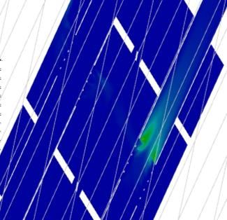
as well as back pressure that improves the performance of the engine. Backpressure is directly related
with the engine performance. Increase in backpressure reduces engine net power, increase the torque
and this can be lead to increase fuel consumption CO emissions and exhaust temperature. Decrease in
back pressure results in increasing in engine efficiency as well as the engine gives maximum output.
Muffler are mainly divided into three types are reactive muffler, absorptive muffler and hybrid
muffler. Hybrid muffler is the combination of the reactive and absorptive muffler. The literature
reviews had considered for this project listed below.
        The design of a muffler chamber, restrictions on the flow of exhaust gases, and the material of
the muffler are all the important factors that affect the muffler’s performance. The backpressure is
inversely proportional to the noise of the muffler; decreasing the noise level will result in increasing
of backpressure. Thus, muffler with low backpressure will have high efficiency[1]. Solid Works is
used to design and analyse the muffler. The muffler was designed with proper measurements.
Dynamic analysis was used to evaluate the shapes, stresses and deformations in muffler. In
comparison to a single expansion chamber, a double expansion chamber produces better
performance[2]. This analysis paper explained the work done by various authors. Several
methodologies that had been used while constructing an exhaust muffler. According to the findings,
there is a large market for open flow or straight through mufflers that are more powerful in terms of
reduced pressure drop and better fuel efficiency[3]. A muffler was created to meet the requirements
of sufficient insertion failure, minimal backpressure, space constraints and the reliability while also
producing the least number of noise. Therefore, a well-designed muffler can provide the best noise
reduction[4].
        A vehicle muffler should be manufactured to meet the functional specifications, including
sufficient insertion loss, space constraints, minimal back pressure, durability, sound production and
cost effectiveness. There are different muffler design solutions for different situations but the design
is proved by the performance[5]. The muffler’s thermal analysis has been evaluated. The results of
the simulated muffler models are extremely useful. In this experiment also explained that the heat
flux would be minimum at the muffler’s initial point and maximum at the opening[6]. Different
designs were developed and simulated in software in comparison to the current muffler of the car.
Based on the simulation design 1 and design 6 are performed much better in terms of pressure loss.
However, merit and demerit are often related and increase in pressure loss would result in increase in
back pressure, which is bad for the engine[7].
        In this project a CFD simulation of an existing muffler was used to calculate the existing
pressure drop, temperature and wall heat transfer coefficient. According to the contour, replacing the

ISSN: 2237-0722                                                                                    1340
Vol. 11 No. 4 (2021)
Received: 19.05.2021 – Accepted: 11.06.2021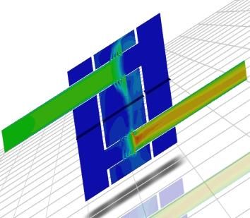
original muffler with a perforation of diameter resulted in a pressure drop[8]. The results of the
experiment showed that the changed design reduces backpressure as compared to the initial design.
The reduction in back pressure would almost certainly result in improved efficiency and longer
engine life while consuming less fuel[9]. The aim of this experiment was to perform a design and free
study of a muffler device in order to evaluate the system’s resonant frequencies and make design
suggestions. The resonance frequencies were calculated by Nastran software, which was then
compiled to determine the peaks were the most important for the device. Side baffles were classified
as weak sections of the muffler based on the results. The suggested design change to mitigate the
effects of these resonance frequencies to add thickness and damping to the device[10].
        The main Objective of this project is to reduce the backpressure in order to increase the
performance of the engine. CFD simulation analyses are done to validate the parameters such as
Pressure, Velocity, Temperature and Turbulence. The work done (Methodology) for this project are
started from the literature survey which is mentioned above, by this the problem was found then we
perform a design works in SolidWorks with the reference of a car muffler, then we perform a
simulation analysis in ANSYS CFD tool to validate the parameters and then the results are
concluded.

2. Materials and Methods

        The materials that will be used for this project as follows SolidWorks (CAD) and ANSYS
(CFD). The modelling and analysing methods are described further down. The use of software to
assist in the development, modification, analysis or optimization of a model is known as computer-
aided design (CAD). CAD software is used to improve the designer’s efficiency, the quality of
design, documentation and development of database for manufacturing. SolidWorks CAD software is
a mechanical design automation programme that enables designers to quickly map out designs,
experiment with features and dimensions and built models and detailed drawings. A SolidWorks
model is made up of 3D geometry that allowing you to build models quickly and accurately.
        The virtual design of the automotive muffler must provide a precise estimation of the space
needed for the exhaust, backpressure to the engine, device weight, gas species distributions and a gas
temperature distribution at a minimum. For a better performance, the Maruti-Suzuki WagnR muffler
is being used as a reference muffler to compare with proposed muffler configurations with the same
or engine exhaust parameters.

ISSN: 2237-0722                                                                                  1341
Vol. 11 No. 4 (2021)
Received: 19.05.2021 – Accepted: 11.06.2021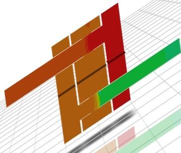
Table 1 - Maruti- Suzuki WagnR Muffler Data
                         Symbol    Parameter                        Dimensions
                         L         Length                           350 mm
                         W         Width                            235 mm
                         H         Height                           135 mm
                         OD        Inlet pipe Diameter              40 mm
                         ID        Inlet pipe Diameter              38 mm
                         OD 1      Outlet pipe Diameter             35 mm
                         ID 1      Outlet pipe Diameter             33 mm
                         d         Diameter of Holes                8 mm
                         N         Number of Perforated holes       45

        A model 1 is created in SolidWorks and simulated in ANSYS CFD using the above-
mentioned muffler data. Figure 1 depicts the view of the muffler model 1. It has three chambers an
inlet, an outlet chamber, a centre as well as perforation tubes and baffles. A model 2 has wide internal
flow tubes that increase exhaust flow while lowering backpressure. On most applications, this
exclusive flow director architecture channels exhaust flow and prevents turbulence. This technology
is also intended to minimise unnecessary interior resonance while retaining a friendly performance
tone. A figure 2 shows the view of model 2. A model 3 is designed with a V-shaped structure that
separates the exhaust gas by sliding their surfaces. As a result, the backpressure of the exhaust gas is
significantly reduced and this design often incorporates excellent sound cancellation. A figure 3
shows the view of model 3.

                                   Fig. 1 - SolidWorks View of Model 1

ISSN: 2237-0722                                                                                    1342
Vol. 11 No. 4 (2021)
Received: 19.05.2021 – Accepted: 11.06.2021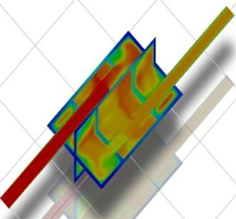
Fig. 2 - SolidWorks View of Model 2

                                   Fig. 3 - SolidWorks View of Model 3

        A computational approach for solving engineering and mathematical physics problems is
known as finite element method (FEM). In order to solve the problem, it divides a broad problem
into smaller sections, which are referred to as finite elements. Finite element analysis is a term used to
describe the method of researching or analysing a phenomenon using FEM (FEA). Computational
fluid dynamics (CFD) is a branch of fluid mechanics that analyses and solves problems involving
fluid flows using numerical analysis and data structures. CFD is seen as a bridge between pure
experimentation fluid dynamics and natural theoretical fluid dynamics. By the CFD analysis, the
complex engineering problems has been reduced significantly. In the CFD analysis, the Geometry is
created in the ANSYS Design Modular or that has been created in a CAD system. ANSYS meshing
is used to find solutions for real flows, a numerical approach must be used, in which the equations are
replaced by algebraic approximations that can be solved using a numerical procedure. The governing

ISSN: 2237-0722                                                                                      1343
Vol. 11 No. 4 (2021)
Received: 19.05.2021 – Accepted: 11.06.2021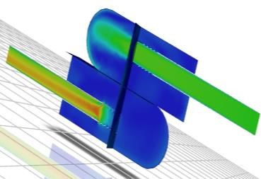
equations are discretized by fragmenting the spatial domain into small finite control volumes with the
aid of mesh.

                                   Fig. 4 - Meshed geometry of Muffler

                                   Fig. 5 - Meshed Geometry of Muffler

                              Table 2 - Boundary Conditions for CFD Analysis
                            Inlet Conditions
                            Inlet velocity                         40 m/s
                            Inlet Temperature                      773 k
                            Density(Constant at temperature)       1.225 kg
                            Outlet Conditions
                            Opening at outlet                      0.05 Pa
                            Outlet Temperature                     300 k
                            Energy                                 On

        For this boundary condition, the analysis was carried out using ANSYS CFD tool. Each
muffler is examined using the same boundary conditions as those described previously.

3. Results and Discussion

        Muffler analysis was performed using the ANSYS CFD tool on severally designed mufflers.
The simulation analysis results are calculated for validation purposes and the outcomes of the various
designs are discussed. The design 1 shows the existing model of the Maruti-Suzuki WagonR car. The
design 2 and design 3 are with the same dimensions of the existing muffler. The dimensions of the

ISSN: 2237-0722                                                                                  1344
Vol. 11 No. 4 (2021)
Received: 19.05.2021 – Accepted: 11.06.2021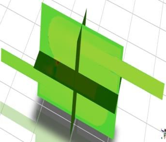
inlet and outlet pipe are kept same and the interior designs are changed and analysed in the ANSYS
CFD.
Fig 6. Pressure Contour of Muffler
Design 1 Design 2 Design 3
From the pressure contour in [figure 6] we can find the maximum pressure in the inlet
chamber of the muffler and gradually decrease in the other chamber. In the mufflers, the maximum
pressure is 3590 Pa and the minimum pressure is 1060 Pa. In the above figure, the outlet pipe shows
the better and minimum pressure drop. When compared with the previous papers, the pressure loss is
about 6105Pa but in this research the pressure loss is about 3590Pa so the pressure loss is gradually
decreased. In the pressure contour figures show that design 3 has a minimum pressure drop when
compared with the other designs.
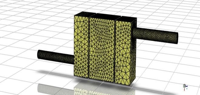
Fig. 7 - Velocity Contour of Muffler
Design 1 Design 2 Design 3
The pressure is inversely proportional to the velocity. The velocity contour [figure 7] shows
that the minimum velocity in the inlet pipe and uniformly in other chambers then maximum in the
outlet pipe. The maximum velocity value is 73 m/s and the minimum velocity value is 0 m/s. Due to
the pressure drop, the velocity at the outlet pipe is much higher. The velocity in the design 1 and
design 2 shows that ununiformed flow or the uneven distribution over the chambers. The design 3
ISSN: 2237-0722 1345
Vol. 11 No. 4 (2021)
Received: 19.05.2021 – Accepted: 11.06.2021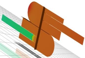
shows the uniform flow of fluid almost all over the chambers. When comparing all the designs, the
design 3 is better. This uniform flow will reduce the turbulence, which is good for the muffler.

                                  Fig 8. Temperature Contour of Muffler
            Design 1                           Design 2                            Design 3

        The temperature contour [figure 8] shows the temperature distribution all over the chambers.
The temperature distribution varies in all the designs. In design 1 and design 3, the temperature varies
from maximum to minimum in all the chambers. In the design 2, the temperature is moderate
throughout all the chambers. The temperature varies according to the engine parameters. The value of
the minimum temperature is 578K and the maximum temperature is 777K.

                                  Fig. 9 - Turbulence Contour of Muffler
            Design 1                              Design 2                        Design 3

        The turbulence contour [figure 9] shows the distribution of fluid all over the chamber. In
design 1 and design 2 show that moderate turbulence formed in the outlet chamber of the muffler. In
the design 3 shows that the fluid flows uniformly (laminar flow) inside the pathway. The maximum
turbulence value is 189 m2/s2 and the minimum turbulence value is 0.05 m2/s2. When comparing the
designs, the design 3 is better. It will distribute the pressure equality all over the chamber and also
increase the performance of the muffler.

ISSN: 2237-0722                                                                                    1346
Vol. 11 No. 4 (2021)
Received: 19.05.2021 – Accepted: 11.06.2021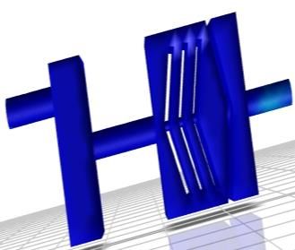
Fig. 10 - Pressure Drop across the model

        [Figure 10] shows that the pressure drop occurred in various designs of mufflers. From the
graph, it is found that design 1 has a maximum pressure drop of 4525Pa, design 2 has a pressure drop
of 3897Pa and design 3 has a minimum pressure drop of 2657Pa. minimum pressure drop will
decrease the back pressure. When compared with the previous papers (6137Pa-4325Pa) and other
designs, the design 3 with the minimum pressure drop (2657Pa) is better. So, the design 3 is best for
using as a muffler in a vehicle where minimum back pressure is required. From this graph, we
obtained that the pressure drop will lead to increased performance.

4. Conclusion

        Various mufflers are compared and then the comparison between the CFD analysis of various
mufflers are noted. The work concluded CFD analysis will be done to determine the Backpressure
along with the parameters analysed such as Pressure, Velocity, Temperature and Turbulence. A paper
described the CFD Analysis of Automotive muffler from modelling to analysis and all works carry on
SolidWorks and ANSYS FLUENT.
        From the simulation results analysed it is concluded that Design 3 is better in pressure drop so
with the maximum pressure drop the back pressure also decreases. The decrease in back pressure
from 4525Pa to 2657Pa results good in performance of the engine. So We can prefer a design 3
among the designs analysed.

ISSN: 2237-0722                                                                                    1347
Vol. 11 No. 4 (2021)
Received: 19.05.2021 – Accepted: 11.06.2021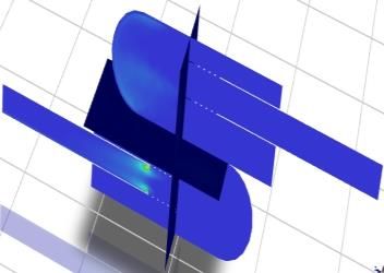
References

Rajasekhar Reddy M, Madhava Reddy K. (2012). Design and optimization of Exhaust Muffler in
Automobiles. Vol. 2 ISSN 2277- 4785.
Praveen R, Kalyana Kumar Mohamed S, Rafi, Mufash Ali, Raj Bharath. (2018). Design and analysis
of automobile Muffler. Volume 118 No. 5, 1053-1060
Potente and Daniel. (2005).          General   design   principles   for   an   automobile   Muffler.
www.daydesign.com.au
Vaibhav D Prajapati, Ankit J Desai. (2016). Design and analysis of automotive muffler. Vol 5 ISSN
2278-0181
Gnanendhar Reddy and Prakash N. (2016). Design and fabrication of Reactive Muffler. ISSN 0972-
768X
Mohiuddin A.K.M, Mohd Rashidin Ideres, Shukri Mohd Hashim. (2005). Experimental study of
noise and backpressure for silencer design Characteristics. ISSN 1812- 5654
Nilesh Kurangal and Dr Sangarampatil. (2020). Experimental testing and CFD Simulation of Existing
Muffler. Volume 07 ISSN 2395- 0056
Christopher George T and Vinod Raj HG. (2018). Energy efficient design and modification of an
automotive exhaust muffler for optimum noise, transmission loss, insertion loss and backpressure: a
review. Sci. Eng. 377 012127
Mohd Umair, Abdul Basit, Arun Prabhakar, Anshul Gautam. (2018). Modification in muffler design
to reduce the backpressure. Vol 5, ISSN 2319- 8753
Venkata Ramesh Mamilla, Sowdagar Moin Ahmed, Lakshmi Narayana Rao. (2016). Design and
analysis of an automobile exhaust muffler. Vol 1 No 1 pp 10-15.

ISSN: 2237-0722                                                                                 1348
Vol. 11 No. 4 (2021)
Received: 19.05.2021 – Accepted: 11.06.2021
You can also read