XP2i Operation Manual - for XP2i-DP Digital Test Gauge - Fagerberg
←
→
Page content transcription
If your browser does not render page correctly, please read the page content below
XP2i Operation Manual
     for XP2i-DP Digital Test Gauge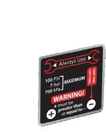
Contents
Overview .  .  .  .  .  .  .  .  .  .  .  .  .  .  .  .  .  .  .  .  .  .  .  .  .  .  .  .  .  .  .  .  .  .  .  .  .  .  .  .  .  .  .  .  .  .  .  .  .  .  .  .  .  .  .  .  .  .  .  .  .  .                1
         Introduction  .  .  .  .  .  .  .  .  .  .  .  .  .  .  .  .  .  .  .  .  .  .  .  .  .  .  .  .  .  .  .  .  .  .  .  .  .  .  .  .  .  .  .  .  .  .  .  .  .  .  .  .  .  .  .  .  .  .  . 1
         Operating Instructions .  .  .  .  .  .  .  .  .  .  .  .  .  .  .  .  .  .  .  .  .  .  .  .  .  .  .  .  .  .  .  .  .  .  .  .  .  .  .  .  .  .  .  .  .  .  .  .  .  . 1
Specifications .  .  .  .  .  .  .  .  .  .  .  .  .  .  .  .  .  .  .  .  .  .  .  .  .  .  .  .  .  .  .  .  .  .  .  .  .  .  .  .  .  .  .  .  .  .  .  .  .  .  .  .  .  .  .  .                            2
         Power .  .  .  .  .  .  .  .  .  .  .  .  .  .  .  .  .  .  .  .  .  .  .  .  .  .  .  .  .  .  .  .  .  .  .  .  .  .  .  .  .  .  .  .  .  .  .  .  .  .  .  .  .  .  .  .  .  .  .  .  .  .  .  .  .  . 3
         Pressure Ranges, Display Scales, and Resolution .  .  .  .  .  .  .  .  .  .  .  .  .  .  .  .  .  .  .  .  .  .  .  .  .  . 5
Applications .  .  .  .  .  .  .  .  .  .  .  .  .  .  .  .  .  .  .  .  .  .  .  .  .  .  .  .  .  .  .  .  .  .  .  .  .  .  .  .  .  .  .  .  .  .  .  .  .  .  .  .  .  .  .  .  .  .                        6
         Differential Pressure  .  .  .  .  .  .  .  .  .  .  .  .  .  .  .  .  .  .  .  .  .  .  .  .  .  .  .  .  .  .  .  .  .  .  .  .  .  .  .  .  .  .  .  .  .  .  .  .  .  .  .  . 6
         Continuous Vacuum  .  .  .  .  .  .  .  .  .  .  .  .  .  .  .  .  .  .  .  .  .  .  .  .  .  .  .  .  .  .  .  .  .  .  .  .  .  .  .  .  .  .  .  .  .  .  .  .  .  .  .  . 7
Safety & Certifications  .  .  .  .  .  .  .  .  .  .  .  .  .  .  .  .  .  .  .  .  .  .  .  .  .  .  .  .  .  .  .  .  .  .  .  .  .  .  .  .  .  .  .  .                                                      8
         Hazardous Locations .  .  .  .  .  .  .  .  .  .  .  .  .  .  .  .  .  .  .  .  .  .  .  .  .  .  .  .  .  .  .  .  .  .  .  .  .  .  .  .  .  .  .  .  .  .  .  .  .  .  .  . 8
         Certifications .  .  .  .  .  .  .  .  .  .  .  .  .  .  .  .  .  .  .  .  .  .  .  .  .  .  .  .  .  .  .  .  .  .  .  .  .  .  .  .  .  .  .  .  .  .  .  .  .  .  .  .  .  .  .  .  .  .  . 8
Support .  .  .  .  .  .  .  .  .  .  .  .  .  .  .  .  .  .  .  .  .  .  .  .  .  .  .  .  .  .  .  .  .  .  .  .  .  .  .  .  .  .  .  .  .  .  .  .  .  .  .  .  .  .  .  .  .  .  .  .  .  .  .  .           9
         Software .  .  .  .  .  .  .  .  .  .  .  .  .  .  .  .  .  .  .  .  .  .  .  .  .  .  .  .  .  .  .  .  .  .  .  .  .  .  .  .  .  .  .  .  .  .  .  .  .  .  .  .  .  .  .  .  .  .  .  .  .  .  . 9
         Replacement Parts .  .  .  .  .  .  .  .  .  .  .  .  .  .  .  .  .  .  .  .  .  .  .  .  .  .  .  .  .  .  .  .  .  .  .  .  .  .  .  .  .  .  .  .  .  .  .  .  .  .  .  .  .  . 9
         Options .  .  .  .  .  .  .  .  .  .  .  .  .  .  .  .  .  .  .  .  .  .  .  .  .  .  .  .  .  .  .  .  .  .  .  .  .  .  .  .  .  .  .  .  .  .  .  .  .  .  .  .  .  .  .  .  .  .  .  .  .  .  .  . 9
         Accessories .  .  .  .  .  .  .  .  .  .  .  .  .  .  .  .  .  .  .  .  .  .  .  .  .  .  .  .  .  .  .  .  .  .  .  .  .  .  .  .  .  .  .  .  .  .  .  .  .  .  .  .  .  .  .  .  .  .  .  . 10
         Contact Us  .  .  .  .  .  .  .  .  .  .  .  .  .  .  .  .  .  .  .  .  .  .  .  .  .  .  .  .  .  .  .  .  .  .  .  .  .  .  .  .  .  .  .  .  .  .  .  .  .  .  .  .  .  .  .  .  .  .  .  . 11
         Factory Service .  .  .  .  .  .  .  .  .  .  .  .  .  .  .  .  .  .  .  .  .  .  .  .  .  .  .  .  .  .  .  .  .  .  .  .  .  .  .  .  .  .  .  .  .  .  .  .  .  .  .  .  .  .  .  . 11
         Trademarks  .  .  .  .  .  .  .  .  .  .  .  .  .  .  .  .  .  .  .  .  .  .  .  .  .  .  .  .  .  .  .  .  .  .  .  .  .  .  .  .  .  .  .  .  .  .  .  .  .  .  .  .  .  .  .  .  .  .  . 11
         Warranty .  .  .  .  .  .  .  .  .  .  .  .  .  .  .  .  .  .  .  .  .  .  .  .  .  .  .  .  .  .  .  .  .  .  .  .  .  .  .  .  .  .  .  .  .  .  .  .  .  .  .  .  .  .  .  .  .  .  .  .  .  . 11
Overview 1
Overview
INTRODUCTION
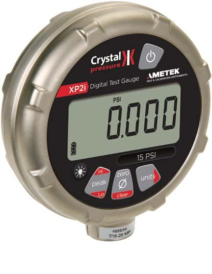
Thank you for choosing the XP2i-DP Digital Test Gauge from Crystal Engineering Corporation. The XP2i-DP is a combination of leading edge
technology, double-sided isolated differential pressure sensing, and rugged industrial design.
Based on the XP2i Series platform, the –DP has all the key features of the product line with additional capabilities that include:
• 0.1% of reading accuracy wet/wet differential transducer
• Excellent performance in long term high vacuum applications
OPERATING INSTRUCTIONS
The XP2i-DP operates just like all the XP2i Series products. The uniqueness of the differential pressure capability comes from the integration of the differen-
tial sensor and process fitting system. The keypad and remote functions are the same as on all XP2i Series products. For further details about these common
features, refer to the XP2i Operation Manual (P/N 4870).
XP2i-DP Operation ManualSpecifications 2
Specifications
Differential Pressure Accuracy
20 to 100% of Full Scale ������������������� ± (0.1% of Reading + Static Line Effect).
0 to 20% of Full Scale ����������������������� ± (0.02% of Full Scale + Static Line Effect).
Static Line Effect: 0.0003 psi/psi of lowest static pressure.
Includes all effects of linearity, hysteresis, repeatability, temperature, and stability for one year.
Temperature
Operating ��������������������������������������������� -10 to 50° C (14 to 122° F).
Non-condensing. No change in accuracy over operating temperature range. Gauge must be zeroed to achieve rated specification.
Storage ��������������������������������������������������� ‑40 to 75° C (‑40 to 167° F).
Battery should be removed if stored for more than one month.
Media Compatibility
Liquids and gases compatible with 300 Series stainless steel and buna-n (o-ring).
Pressure Conversions
1 psi = 27.6806 inches of water column (water at 4° C [39.2° F])
27.7070 inches of water column (water at 15.6° C [60° F])
27.7292 inches of water column (water at 20° C [68° F])
2.03602 inches of mercury (mercury at 0° C [32° F])
51.7149 millimeters of mercury (mercury at 0° C [32° F])
703.087 millimeters of water column (water at 4° C [39.2° F])
0.070307 kilograms per square centimeter
68.948 millibar
6.8948 kilopascals
0.068948 bar
0.006895 megapascals
XP2i-DP Operation ManualSpecifications 3
Connections
Pressure Connections ����������������������� 1/8" Female NPT (both + and – ports).
Communication ��������������������������������� DB9, RS-232 (environmentally sealed).
Note: Do not use the RS-232 connector in a hazardous atmosphere.
Display
Screen ����������������������������������������������������� 5.5 digits.
Display Rate ����������������������������������������� 4 readings/second (standard).
8 readings/second (PSV mode).
Numerical Display Height ��������������� 16.9 mm (0.67") single line display. LCD readable in sunlight with bright backlight.
Enclosure
(U.S. Patent D612277)
Weight ��������������������������������������������������� 915g (2.0 lbs), including batteries.
Dimensions ������������������������������������������� 165.1 mm (6.5") H x 112 mm (4.4") W x 33 mm (1.3") D.
Rating ����������������������������������������������������� IP67.
Housing ������������������������������������������������� Diecast, nickel plating over low copper, marine grade aluminum.
Keypad and Labels ����������������������������� UV Resistant Polyester.
Sensor
Permanent fill dual diaphragm seal (filled with Dow Corning 200).
Max Static Line Pressure ������������������� 100 psi.
POWER
Batteries ������������������������������������������������� Three size AA (LR6) batteries.
!!WARNING: Do not remove or change the batteries in hazardous locations.
XP2i-DP Operation ManualSpecifications 4
Approved Batteries
The XP2i-DP is Intrinsically Safe only if powered by one of the following battery types:
Approved Battery Type Ta= Marking
Rayovac Max Plus 815
-20 to 50° C Ex ia IIC T4 Ga
Energizer E91*
Energizer EN91*
-20 to 50° C Ex ia IIC T3 Ga
Duracell MN1500
Replace batteries with approved type in non-hazardous locations only
* Energizer is manufactured by Energizer Holdings, Inc., and the Eveready Battery Company, Inc.
Many other battery types and models have been tested but failed to meet the requirements for Intrinsic Safety—do not assume other models are equivalent.
The XP2i-DP can be operated from an external power supply (P/N 2984).
Do not mix battery types or manufacturers.
XX CSA: The XP2i is Intrinsically Safe only if powered by one of the following battery types:
Approved Battery Type Ta= Marking
Rayovac Max Plus 815 -20 to 45° C Class I, Division 1, A, B, C, D T4
Energizer E91
Energizer EN91 -20 to 50° C Class I, Division 1, A, B, C, D T3C
Rayovac Max Plus 815
!!WARNING: Use of Duracell MN1500 batteries is not approved for CSA certification.
!!WARNING: Do not use the AC Adapter kit in hazardous locations.
Battery Life ������������������������������������������� 1500 hours typical (alkaline battery).
Ultra Low Power ��������������������������������� > 1 year, typical with 20 minute recording interval in LT5 mode.
Battery Indicator ��������������������������������� 3-segment Battery Icon:
( ) : Full Battery
( ) : Used Battery
( ) : Low Battery
Dead Battery Indication ������������������� batt
XP2i-DP Operation ManualSpecifications 5
PRESSURE RANGES, DISPLAY SCALES, AND RESOLUTION
psi bar kPa MPa Overpressure (+/– ports) psi inH20 inHg mmHg mmH20 kg/cm2 bar mbar kPa MPa
15PSI 1BAR 100KPA 0.1MPA 6.5 x / 3.0 x 0.001 0.01 0.001 0.01 1 0.0001 0.0001 0.1 0.01 0.00001
100PSI 7BAR 700KPA 0.7MPA 2.0 x / 2.0 x 0.01 0.1 0.01 0.1 1 0.0001 0.0001 0.1 0.01 0.00001
• Unneeded pressure units may be disabled via the RS-232 connector using ConfigXP software.
• An XP2i-DP will indicate pressure up to 10% above its stated pressure rating. Above 110%, the XP2i-DP display will flash, indicating that the applied pressure
exceeds the calibrated pressure range. If the calibrated pressure range is exceeded, the pressure displayed may not be accurate.
• Overpressure is the maximum pressure the gauge can withstand without damage. The gauge will not indicate pressure up to this value.
• kPa and MPa models can display pressure in kPa, MPa, and bar (and/or mbar) only. psi and bar models can display all available units.
XP2i-DP Operation ManualApplications 6
Applications
DIFFERENTIAL PRESSURE
The XP2i-DP may be used to determine accurate differential pressure measurements across a range of applications or installations such as filters,
orifice plates, valves, etc. For example, in a piping system with an upstream static pressure of approximately 80 psig, the XP2i-DP may be used to
determine the 10 psid pressure drop across the device under test (DUT). In this case, the product would be connected as shown below.
XP2i Digital Test Gauge
100 PSID
Hi
zero
peak
units
Lo
clear
XP2i-DP
FLOW 80 70
PSI PSI
Device Under Test (DUT)
The pressure measurement accuracy of the gauge in this example is a combination of the standard accuracy statement and the static line pres-
sure effect. The 10 psid pressure, when compared to the 100 psi full scale product used, will require the 0 to 20% of Full Scale, ± (0.02% of Full
Scale) accuracy statement. The static line pressure effect relates to the lowest test pressure applied in the test, or in this case 70 psi.
The pressure measurement accuracy for this test condition is as follows:
± (0.02% x 100 psi) + (0.0003 psi x 70 psi) = ± 0.04 psi.
When using a 15 psi full scale gauge, this will require the 20 to 100% of Full Scale, ± (0.1% of Reading) accuracy statement.
± (0.1% x 10 psi) + (0.0003 psi x 70 psi) = ± 0.031 psi.
XP2i-DP Operation ManualApplications 7
CONTINUOUS VACUUM
The unique design of the differential pressure sensor integrated into the XP2i-DP allows for long term vacuum use without fear of permanent damage to the
sensing chip or package. When measuring high vacuum gauge pressures continuously it is recommended to connect the static line pressure to the right (–)
port marked "Vacuum this side". To achieve gauge measurements, the left (+) port is left vented to atmospheric pressure.
Vent Vacuum
Note: When connected in this orientation, the XP2i-DP display will invert the sign on the gauge display. For example, a pressure of -12 psi on the negative
port will display +12 psi. To invert the sign to read -12 psi, use ConfigXP Software (V 2.4 or later).
Select Enable Vacuum Mode and update the gauge to properly display a negative pressure value.
!!WARNING: Pressure applied to the + sensor port must be greater than or equal to the pressure applied to the – sensor port.
The vacuum accuracy of the gauge will be calculated the same as a differential measurement. Therefore, the 12 psi measurement, when compared to a 100
psi full scale gauge used, will require the 0 to 20% of Full Scale, ± 0.02 % of Full Scale accuracy statement.
The vacuum accuracy for this test condition is as follows:
± (0.02% x 100 psi) = ± 0.02 psi.
When using a 15 psi full scale gauge, this will require the 20 to 100% of Full Scale, ± (0.1% of Reading) accuracy statement.
± (0.1% x 12 psi) = ± 0.012 psi.
XP2i-DP Operation ManualSafety & Certifications 8
Safety & Certifications
HAZARDOUS LOCATIONS
Every XP2i-DP pressure gauge includes the following Intrinsic Safety approvals:
II 1G Ex ia IIC T4/T3 Ga Intrinsically Safe and Non-incendive for Hazardous Locations: Class I, Division 1,
ATEX FTZU 12 ATEX 0048X Groups A, B, C and D, Temperature Code T4 or T3C.
This product conforms to the following standards:
EN 60079-0 : 2009 | EN 60079-11: 2012 | EN 60079-26: 2007
Ex ia IIC T4/T3 Ga
IECEx FTZU 12.0009X
This product conforms to the following standards:
IEC 60079-0 : 2011 | IEC 60079-11: 2011-06 | IEC 60079-26: 2006
!!WARNINGS: The following warnings apply to the XP2i:
• Do not use the RS-232 connector in hazardous locations.
• Replace batteries in non-hazardous locations and with approved types only.
• Do not mix battery types or manufacturers.
• T4 or T3 Temperature Class is based on selection of approved battery. See Approved Batteries on page 4.
• Special conditions for safe use:
• The equipment shall not be installed in a location where external conditions are conducive to the buildup of electrostatic charge.
• Because the enclosure of the XP2i and XP2i-DD is made of aluminium, if it is mounted in an area where the use of category 1 G apparatus
is required, it must be installed such that, even in the event of rare incidents, ignition sources due to impact and friction sparks are excluded.
CERTIFICATIONS
The XP2i-DP has been tested and certified to comply with a variety of international standards.
This XP2i-DP complies with the Australian requirements for the C-tick mark.
C-tick The instrument was tested against AS/NZS 3584, C-tick EMC/EMI requirements.
Crystal Engineering declares that the XP2i-DP is in accordance with the ATEX Directive, the Electromagnetic Compatibility Directive, and the Pressure
Equipment Directive per our declaration(s).
This XP2i-DP is approved for use as a portable test instrument for Marine use and complies with Det Norsjke Veritas’ Rules for Classification of Ships,
High Speed & Light Craft, and Offshore Standards.
XP2i-DP Operation ManualSupport 9
Support
SOFTWARE
ConfigXP Configuration Software
Use ConfigXP to disable unwanted pressure units, set default pressure units, change water density, adjust calibration, and more via the RS-232 interface.
DataLoggerXP Software
DataLoggerXP is an optional upgrade to transform the XP2i-DP into a pressure datalogging device.
REPLACEMENT PARTS
The only user-replaceable parts are the batteries.
OPTIONS
Panel Mounting (Option F4)
A panel mount flange allows an XP2i-DP to fit in a 4½" gauge cutout. An XP2i-DP with the F4 option can also be adapted to 6 or 8½" gauge cutouts.
Rear Port Fitting (Option RP)
The rear port fitting may be ordered separately, but is included automatically with the panel mount flange option (F4).
XP2i-DP Operation ManualSupport 10
ACCESSORIES
P/N 2984 AC Adapter Kit
Permits operation of an XP2i-DP from an AC supply of 90 - 264 VAC and 47 - 63 Hz. Includes interchangeable international plugs (for USA, Europe, U.K., and Australia).
Adapter will not charge batteries, but in the event of AC power loss, XP2is will automatically revert to battery operation.
!!WARNING: Do not use the AC Adapter Kit in hazardous locations.
P/N 3696 Protective Boot
Skydrol™ resistant protective boot.
!!WARNING: Do not use the Protective Boot in hazardous locations.
P/N 2955 6" Gauge Adapter Kit
Adapts the 4½" Panel Mount (F4 option) to fit into a 6" gauge cutout.
P/N 2956 8½" Gauge Adapter Kit
Adapts the 4½" Panel Mount (F4 option) to fit into an 8½" gauge cutout.
P/N 3313 USB-RS232 Adapter
USB B receptacle to RS232 DB9M.
!!WARNING: Do not use the USB-RS232 Adapter in hazardous locations.
P/N 2400 RS232 Cable
DB-9 male to DB-9 female straight pass-through cable.
!!WARNING: Do not use the RS232 Cable in hazardous locations.
XP2i-DP Operation ManualSupport 11
CONTACT US
Phone ��������������������������������������������������� (805) 595-5477
Toll-Free ����������������������������������������������� (800) 444‑1850
Fax ����������������������������������������������������������� (805) 595-5466
Email ����������������������������������������������������� crystal@ametek.com
Web ��������������������������������������������������������� crystalengineering.net
FACTORY SERVICE
Please complete the Return Material Authorization (RMA) form on our website. This will generate an authorization number and provide return instructions.
TRADEMARKS
This manual contains the following third-party trademarks, both registered and unregistered. All marks are the property of their respective companies.
Rayovac® and Maximum Plus™ . . . . . . . . . . . . . . . . . Rayovac Corporation
Duracell®. . . . . . . . . . . . . . . . . . . . . . . . . . . . . . . . . . . . . . Duracell Inc. Corporation
Energizer® and Eveready. . . . . . . . . . . . . . . . . . . . . . . Eveready Battery Company, Inc.
“Pressure is Our Business” is a registered trademark of Crystal Engineering Corp.
WARRANTY
Crystal Engineering Corporation warrants the XP2i-DP Digital Test Gauge to be free from defects in material and workmanship under normal use and service
for one (1) year from date of purchase to the original purchaser. It does not apply to batteries or when the product has been misused, altered or damaged by
accident or abnormal conditions of operation.
Crystal Engineering will, at our option, repair or replace the defective device free of charge and the device will be returned, transportation prepaid. However, if
we determine the failure was caused by misuse, alteration, accident or abnormal condition of operation, you will be billed for the repair.
CRYSTAL ENGINEERING CORPORATION MAKES NO WARRANTY OTHER THAN THE LIMITED WARRANTY STATED ABOVE. ALL WARRANTIES, INCLUDING IMPLIED
WARRANTIES OF MERCHANTABILITY OR FITNESS FOR ANY PARTICULAR PURPOSE, ARE LIMITED TO A PERIOD OF ONE (1) YEAR FROM THE DATE OF PURCHASE.
CRYSTAL ENGINEERING SHALL NOT BE LIABLE FOR ANY SPECIAL, INCIDENTAL OR CONSEQUENTIAL DAMAGES, WHETHER IN CONTRACT, TORT OR OTHERWISE.
Note: (USA only) Some states do not allow limitations of implied warranties or the exclusion of incidental or consequential damages, so the above limitations
or exclusions may not apply to you. This warranty gives you specific legal rights and you may have other rights which vary from state to state.
XP2i-DP Operation Manual© 2015 Crystal Engineering Corporation
708 Fiero Lane, Suite 9, San Luis Obispo, California 93401-8701
4871. FYou can also read