Analyzing performance for lighting of tessellated grass using LOD - Emil Johansson
←
→
Page content transcription
If your browser does not render page correctly, please read the page content below
Bachelor of Science in Digital Game Development
May 2021

  Analyzing performance for lighting of
      tessellated grass using LOD

                              Emil Johansson

Faculty of Computing, Blekinge Institute of Technology, 371 7nine Karlskrona, Sweden
This thesis is submitted to the Faculty of Computing at Blekinge Institute of Technology in partial fulfilment of the requirements for the degree of Bachelor of Science in Digital Game Development. The thesis is equivalent to 10 weeks of full time studies. The authors declare that they are the sole authors of this thesis and that they have not used any sources other than those listed in the bibliography and identified as references. They further declare that they have not submitted this thesis at any other institution to obtain a degree. Contact Information: Author(s): Emil Johansson E-mail: emjp18@student.bth.se E-mail: University advisor: Assistant Professor Prashant Goswami Department of Computer Science Faculty of Computing Internet : www.bth.se Blekinge Institute of Technology Phone : +46 455 38 50 00 SE–371 7nine Karlskrona, Sweden Fax : +46 455 38 50 57
Abstract

Background
There are different methods for rendering grass in real-time, for video games. This
thesis looks at an algorithm that uses hardware tessellation to generate geometry
during run time. These concepts are explained in more detail in the introduction
chapter as well as the method chapter.
Objectives
The problem that this thesis revolves around is this; When rendering grass using
tessellation a lot of geometry is created. This means that the grass might be a bot-
tleneck, meaning it eats too much performance. This applies especially when adding
lighting to a scene dense with grass. Lighting requires a lot more computations, so
adding this can create a difference, a "dip" in performance. To try and aid this dip,
LOD in different forms will be added. Then tests will be carried out to see if the
divide is lessened. This would allow for a lot of lighting to be used together with
this expensive technique. LOD means a way to lessen the geometry being rendered
through different algorithms so that the performance cost will not be as high.
Methods
To answer the relevant research questions, a literature review was carried out. This
to understand the relevant 3D techniques better. And also to learn more about ren-
dering grass through tessellation. Then an implementation was conducted, with this
an experiment to test different LOD techniques with and without lighting. Each
scenario was tested ten times and the average framerate was measured and put into
charts.
Results
The average framerate dropped when light sources were added in all of the tests.
The binary tree consumed more RAM usage but aided the framerate more than the
quadtree. The VRAM usage for the grass tessellation was around 100 MB.
Conclusions
For future work, it would be interesting to compare different ways of rendering grass
for the sake of user value. Do people prefer tessellated grass when minimal lighting
is applied? Or do people prefer quads to represent grass? The results did not show
that the LOD implemented solved the issue presented in this thesis.

Keywords: Tessellation, LOD, Grass
Contents

Abstract                                                                                                                       i

1 Introduction                                                                                                                1
  1.1 Background and Scope .        . . . . . .   .   .   .   .   .   .   .   .   .   .   .   .   .   .   .   .   .   .   .   1
       1.1.1 Rendering Grass        . . . . . .   .   .   .   .   .   .   .   .   .   .   .   .   .   .   .   .   .   .   .   1
       1.1.2 Motivation . . . .     . . . . . .   .   .   .   .   .   .   .   .   .   .   .   .   .   .   .   .   .   .   .   1
       1.1.3 Thesis Structure       . . . . . .   .   .   .   .   .   .   .   .   .   .   .   .   .   .   .   .   .   .   .   2
  1.2 Explanation of Recurring      Concepts      .   .   .   .   .   .   .   .   .   .   .   .   .   .   .   .   .   .   .   3
  1.3 Algorithms . . . . . . . .    . . . . . .   .   .   .   .   .   .   .   .   .   .   .   .   .   .   .   .   .   .   .   5
       1.3.1 Binary Tree . . .      . . . . . .   .   .   .   .   .   .   .   .   .   .   .   .   .   .   .   .   .   .   .   5
       1.3.2 Quad Tree . . . .      . . . . . .   .   .   .   .   .   .   .   .   .   .   .   .   .   .   .   .   .   .   .   5
       1.3.3 Grass Algorithm        . . . . . .   .   .   .   .   .   .   .   .   .   .   .   .   .   .   .   .   .   .   .   6
  1.4 Outline . . . . . . . . . .   . . . . . .   .   .   .   .   .   .   .   .   .   .   .   .   .   .   .   .   .   .   .   7

2 Related Work                                                                                                                 9

3 Method                                                                                                                      11
  3.1 Protocol . . . . . . . . . . . . . . . . . . . . . . . . . . . . . . . . . .                                            11

4 Results and Analysis                                                                                                        15

5 Discussion                                                                                                                  19

6 Conclusions and Future Work                                                                                                 21

                                          iii
Chapter 1
Introduction
1.1 Background and Scope
1.1.1 Rendering Grass
This thesis explores rending grass in real-time, meant for video games. There are
different methods of doing this. When trying to be as accurate as possible to reality,
the process becomes troublesome performance-wise. Grass in reality consists of many
small strands. Instead of rendering all of this geometry, another method is described
by Jahrmann and Wimmer [7]. This method is using transparent billboarded quads.
Billboarded means they always turn so that the front slide is facing the camera. This
way it is not necessary to render the backside of the quad. These quads have textures
on them simulating many strands of grass. Another method is to use something
called tessellation to generate strands during run time. However, this means a lot
of geometry is created and as mentioned by Jahrmann and Wimmer [8], to use each
strand as a piece of geometry might result in a bottleneck. A Bottleneck here means
that it slows down the performance. Applying lighting to a scene with tessellated
grass might slow down performance even more. Hence different methods called “level
of detail” or LOD. are used to try and tackle this issue. This thesis is about rendering
grass using tessellation, apply lighting to push for a drop in performance. Drop here
means that the frame rate is expected to be lowered when using lighting. Then the
LOD method will be applied to see if this drop can be aided or maybe even fixed.
Applying light can enhance the visual aspect of a scene. To ensure the performance is
not damaged is therefore vital to make a scene look good without the cost of slowing
things down.
1.1.2 Motivation
There are examples of where the grass is rendered through tessellation. However,
applying lighting to such extensive geometry has proven to drastically lower the
performance in custom past implementations. Also, the examples where lighting
techniques are applied to dense scenes of grass, tessellation is not used. Because
tessellation creates a lot of geometry adding lighting to such a scene is not always
optimal. It is therefore relevant to add LOD to such a scene where the lighting does
lower the performance to the point it is not worth using it. To see if the LOD would
rescue the performance. Allowing lighting can enhance the visual appearance and
can lead to other techniques such as shadows that can also improve the user value.
12 Chapter 1. Introduction
1.1.3 Thesis Structure
1. Aim
This thesis aims to try to apply lighting to a dense scene of tessellated grass
blades and a LOD method. Then the performance will be measured and com-
pared with the same scene but without lighting. This is to see if LOD can
significantly help in performance. The performance will be measured mainly
through frame rate, however, RAM and VRAM usage will also be looked at.
2. Objectives
• Build a custom engine so the tests can be carried out.
• Construct the necessary 3D techniques, this being a binary tree, a quadtree,
and the algorithm for rendering grass.
• Run the experiments ten times and generate results to put into charts.
3. Research Questions
• When using hardware tessellation to render grass, can lighting be used
on the grass blades without a significant drop in performance, helped by
either a quadtree or a binary tree?
• Between a binary tree and a quad tree, when rendering grass using hard-
ware tessellation, what offers less of a performance dip when lighting is
applied?
4. Hypothesis
The hypothesis for the implementation is the following. Using LOD should
speed up the performance but might cost in pre-computation. A binary tree
will likely help more than a quadtree, and they will help enough to not create
a huge dip in frame rate when rendering a lot of grass with lighting.
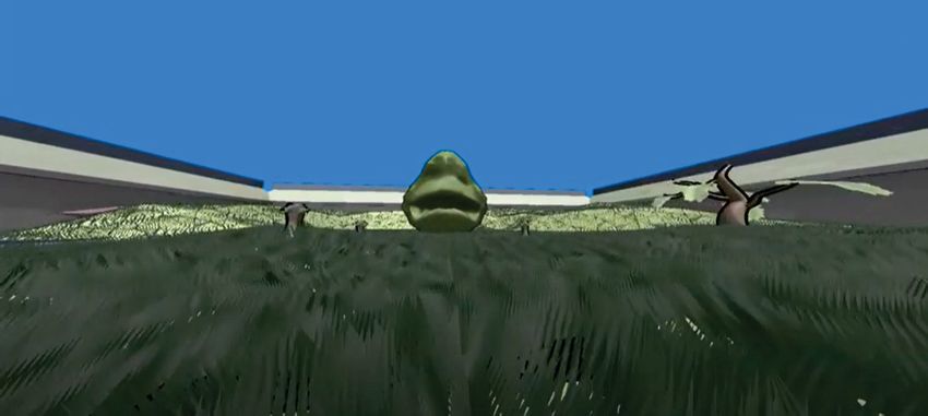
Figure 1.1: An example image of generated grass blades. In this case, they are dense
but only a directional light source is present. They also utilize physically based
textures.1.2. Explanation of Recurring Concepts 3
Figure 1.2: Another example where the grass is rendered. This time from a different
angle.
1.2 Explanation of Recurring Concepts
1. Polygons
Polygons are the smallest parts of a mesh. They can take many shapes but
are usually triangles. Each corner of that polygon is a vertex, which contains
information such as position, texture coordinates, and a normal vector. What
a vector is, will not be explained in this thesis, but for more information about
that subject, please refer to Christer Ericson [4]. Between the corners of a
polygon are “edges”.
2. Level of detail
LOD stands for “level of detail”, and it means to apply an algorithm to manage
scene geometry. The purpose of sorting a scene’s geometry is to keep wasteful
geometry from being sent down the rendering pipeline. Dividing a scene or
a mesh can be useful to control what is processed by the GPU and what is
not. What a GPU is will not be explained by this thesis either. For more
information, please refer to Tomas Akenine-Mo Ller et al. [15].
3. Viewing Frustum
A “Viewing Frustum” is the volume for which objects are visible inside a camera.
The camera in a scene has six planes consisting of its viewing frustum, top,
bottom, left, right, near, and far. These planes can be extracted in real-time
and used for intersection tests. These tests allow the engine to know when
objects are visible by the camera or not. Meaning they can be culled before
they get processed by the GPU. For more information, please refer to Tomas
Akenine-Mo Ller et al. [15].
4. Axis Aligned Bounding Box
Axis Aligned Bounding Boxes, are primitives in the form of boxes. These
boxes are axis-aligned, meaning they have no rotation concerning the world.
If the world points in one direction, the boxes point the same. The reason
to construct boxes is to confine geometry in them. The boxes can be tested
against the viewing frustum, if they are not visible all of the geometry within
can be culled. This is convenient because it means all of the geometry within
does not need to be tested against the viewing frustum, only the simple boxes.
For more information, please refer to Christer Ericson [4].
5. Micro Geometry
Micro Geometry refers to when lighting is applied to materials, how the light4 Chapter 1. Introduction
behaves due to the microgeometry of these materials. On a very small level,
the geometry might be rough or smooth. Depending on this the light will be
reflected or scattered within the material. For more information, please refer
to Tomas Akenine-Mo Ller et al. [15].
6. Dielectrics and Semi Conductors
Dielectrics and Semi-Conductors refer to different types of materials. They can
be categorized into different sections, Dielectrics are materials such as glass that
refract light. Semiconductors can be metals that can completely reflect light.
And completely absorb it too. Metals when used in real-time should not be
half metals, they should be represented with a value that is either 1 or 0, on or
off, white or black. This is because half metals are much more difficult to deal
with. For more information, please refer to Tomas Akenine-Mo Ller et al. [15].
7.
8. Lighting
Lighting can enhance the value of a scene, the lighting calculations relevant
for this thesis are that of physically based. Physically-based light mimics real
physics. A big part of this is microfacet theory, which is the basis for simulating
microgeometry. A rough geometry has the light bounce back and forth and not
be as reflective, this is the basis to calculate specular light. Which is explained
by Tomas Akenine-Mo Ller et al. [15]. The light that escapes is what is visible
and determines the color - the albedo. Usually, an object has multiple materials,
some can be dielectric other semiconductors, the blending of different materials
is called baking and creates textures used for geometry. Different textures can
have different properties, metals for example are reflective. When calculating
lighting inside a shader, it can cost performance-wise on the GPU. For more
information, please refer to Tomas Akenine-Mo Ller et al. [15].
9. Hardware Tessellation
Hardware Tessellation for DirectX was introduced along with DirectX 11. They
essentially enable the user to break down a mesh into more polygons during run
time, which creates more detail, enabling a more refined shape or more fluid
animations. It does so by creating polygons on the fly, during run time. This
thesis uses tessellation as a way of creating blades to simulate grass. Another
option for simulating grass is as explained by Jahrmann and Wimmer [7], using
billboarded textures. Tessellating the blades has some positive aspects. Such is
the control over each blade, bending them using Bezier curves, giving patches
collision so they can react to people walking on them, or to forces like wind.
When looking at billboarded textures from a top view, they can also look less
realistic. However, since using tessellation means essentially each blade is a
piece of geometry, it means a lot of calculations are needed to be done when
applying light. This can create a bottleneck so applying lighting with this
technique might not be a good idea. For more information, please refer to
Tomas Akenine-Mo Ller et al. [15].1.3. Algorithms 5 1.3 Algorithms 1.3.1 Binary Tree The implementation worked by building a binary tree, which is explained by Ericson [4], Wang et al. [9], Bao et al. [2] also Lu and Chang [11]. It divides the scene into nodes based on what side the relevant polygons lie on, divided by custom constructed planes. These nodes can then construct axis-aligned bounding boxes based on the polygons in them. When traversing the tree these bounding volumes can be tested against the planes of the camera’s viewing frustum. And be culled when it’s not visi- ble, since multiple nodes containing polygons are never sent down the GPU pipeline, a boost in performance is gained. When constructing the tree, the planes chosen are not completely arbitrary. To make it more balanced, they are chosen based on the current list of polygons being traversed and finally a polygon in that list. When a polygon is on different sides of a plane, it is split in two. The edges of the polygon are considered lines and intersection tests are made to determine where to construct the new vertices. As for the normal and texture coordinates, This information is found by interpolating the other vertex information with a t value found thanks to the position being found through the intersection test. Polygons inside the plane are considered as part of the frontlist. The plane is also given a thickness using an epsilon, which is just a small number. This helps with the classification tests, meaning the tests to see on what side the current polygon lies. The following figures showcase how the different LOD methods were applied to a terrain used later in the experiments. Figure 1.3: This is a wire frame of the base terrain constructed through a binary tree. In some places, there has been CPU-based tessellation as the polygons have been split. 1.3.2 Quad Tree The quadtree works in a similar way as the binary tree, except the scene is divided into nodes based on axis-aligned bounding boxes. If these boxes contain a triangle count higher than a custom threshold, then they are further divided into smaller
6                                                             Chapter 1. Introduction

axis-aligned bounding boxes. For this implementation, the relevant geometry is split
to fit inside the different boxes.

Figure 1.4: This figure visualizes how the terrain used for this thesis was surrounded
by axis-aligned bounding boxes, inside of these boxes is where the terrain is supposed
to be, and there are smaller boxes to cover portions of the mesh.

1.3.3     Grass Algorithm
The grass algorithm used in this example utilizes the tessellation stages to create the
grass blades. This technique much like Jahrmann and Wimmer [8] can be applied to
any type of mesh. A mesh is defined to be used as a basis for the grass, in this case,
it’s a sculpted plane. The vertex information of this mesh is sent to the GPU through
structured buffers. Besides vertex information, to reach it the indices are sent in as
well, also using a structured buffer. When the grass is rendered, no vertex buffer
is needed, however, the index buffer contains the number of triangles of the base
mesh and tells how many times to invoke the shader. Inside the vertex shader, using
built-in semantics, the current vertex ID can be found and therefore what triangle is
currently being used. Using this to obtain the correct indices and vertices from the
structured buffers, the center of the triangle can be found. This point is then used
along with the camera to determine a current distance. Depending on this distance
a different tessellation factor is set. Meaning the density of the grass decreases the
further away from the camera it is. This is a common way to control LOD based on
distance when using hardware tessellation. After the vertex shader, the first of the
3 tessellation stages are in effect – the Hull shader. This stage has two outputs. It
needs to determine the tessellation factors, in this case, line strips are what should be
generated. Two factors need to be determined, one is the density factor, how many
lines per triangle should be generated? And the other is how smooth the lines should
be, the smoothness could be useful if for example Bezier curves are used to make the
grass blades bend. With the structured buffers, texture coordinates for the center of
the current triangle can be found. If for example a height map was used to generate
the terrain, certain areas can be masked off, so that there is no tessellation at some
portions of the terrain. Since most of the information comes from the structured
buffers, like in the example described by Jahrmann and Wimmer [8], there is not
1.4. Outline                                                                           7

much information that needs to be passed through the vertex or the hull shader
stage. The actual tessellation stage is not a programmable shader stage, so after
the hull shader and the tessellation shader, comes the domain shader. The job of
this shader is to interpolate the data using generated texture coordinates. Because
line strips are generated, two texture coordinates are generated as well. However,
since the vertex data is that of triangles. A third one is created manually with the
assumption they all add up to one. It is possible to simulate wind, by creating
a displacement for the final positions, using a value that changes over time, or a
pseudo-random value. A texture can also be used. To not have a uniform height
a random value for each strand can also be used to give them a slight difference in
appearance. After the domain shader, the final shader stage where geometry is still
relevant is the geometry shader. The job in this case for the geometry shader is to
expand the lines into quads. The quads need to be very thin for the grass to look
like blades, so the screen resolution can be used to create a thin size. The quads
are in this example billboarded meaning they always face the camera. This way
they don’t need to be rendered with the back as well, and they will not end up being
rendered from the side. Besides being billboarded, the quads are also displaced along
with the normal information. This means the strands will not point up in the world
but outwards in tangent space from whatever triangles they originate in. The final
shader stage is the pixel shader, where the geometry is not being processed anymore,
but instead, rasterization has generated pixels. The option is then to either perform
lighting calculations or to just render the albedo texture as it is. That’s how the
grass algorithm for this example works.

Figure 1.5: In this figure there is a scene with tessellated grass blades, from a distance
there is not as much tessellation, this is the LOD method based on distance.

1.4     Outline
This thesis consists of the following chapters. Method, Result and Analysis, Discus-
sion, Conclusion, and Future Work. The Method goes through how the implemen-
tation was performed, explains the techniques used, and under what circumstances
the experiments were done. Results and Analysis show the findings of each experi-
ment. The discussion puts the finding in a wider context and discusses what might
have given different results. Finally, the conclusion and future work reaches a verdict
8                                                         Chapter 1. Introduction

Figure 1.6: The blades in this image are billboarded but they don’t point straight
up, instead they point out from the mesh because they have been displaced along
the normals.

based on the discussion and also mentions what future projects could be implemented
after this.
Chapter 2
                                                           Related Work

There are works describing similar methods of rendering grass as in this project. As
well as other works describing different techniques of rendering grass. Jahrmann and
Wimmer [7] describe in their paper, rendering grass through tessellation accompanied
by various methods of LOD. Since each blade is a piece of geometry, the grass can
be deformed by wind or other objects. They also however explain that since each
blade is a piece of geometry it does not scale well, performance-wise. They also
use instancing, meaning they don’t send more than one patch of grass as a draw
call down the GPU. Jahrmann and Wimmer [8] also, consider grass rendering a
potential problem performance-wise due to the potential need for massive amounts
of geometry. They argue an approach that can be applied to any model, not just a
terrain or a heightmap. The grass is still generated procedurally but can be applied
for example as fur as well. They also use hardware tessellation and allow each blade
to be affected by external forces such as collision or gravity. The paper says grass
techniques can be divided into image-based, geometry-based, or hybrid approaches.
Image-based are the most common, a drawback of this is that as mentioned in a
previous paper, the quality suffers when viewed from certain angles. Realism also
suffers when trying to animate these billboards, for example, to simulate wind. To
achieve what they call “indirect rendering”, they send the rendering data down the
GPU from buffers. This is how they can draw grass on any 3D model, not just a
heightmap. This is similar to the technique used for this thesis. When they do their
culling, the simulation of grass is considered, meaning if the grass can sway a certain
distance, then the bounding box surrounding it has been increased to account for this
possibility. Not only do they cull the bounding box against the camera’s frustum,
but they also do an orientation test, since the planes have a tiny width, aliasing
can occur when the blades are parallel since the width can be smaller than a pixel.
To solve this they use cosine in a calculation to find the orientation and culls the
blade if it exceeds a certain threshold. After the bounding box has been tested, they
also test individual blades. This is done by testing 3 points of the blade, if all 3
fails/succeeds in the test, the blade is culled. As a final test, they also cull based
on distance from the camera, which is typical for tessellated geometry. Boulanger
et al. [3] as well as Qiu and Chen [13] Also, render a large-scale grass field with
lighting But they do not use tessellation. Boulanger et al. [3] succeeds in adding
shadows on the grass. Something not recommended when the grass is too detailed
given the performance issues. shadows can enhance the user value of a scene. Their
technique is using semi-transparent quadrilateral strips textured with photo-realistic
grass. They also render the grass in batches which minimizes the number of draw

                                          9
10 Chapter 2. Related Work calls. A LOD method they use is to control the density of their grass using density maps. Qiu and Chen [13] argues grass is difficult to render in real-time due to its geometric complexity. They use a method they call 2D sketch-based. Their goal is not to have grass straws on small areas but to have a lot of them on giant areas. They use geometry shaped like grass up close and from a distance, they use a volumetric texture-based method. Franzin et al. [5] use the GPU to create vegetation in real- time. They render in batches and uses instancing on the GPU. They also use a compute shader to distribute the vegetation. They also have a system for collision detection that can bend the grass due to external forces. They do not use tessellation but instead billboards for the actual geometry. Lee et al. [14] try to simulate realistic wind effects with GPU-based grass rendering. They focus on applying a realistic wind effect by bending the geometry using Bezier curves. Their solution scales well and they can create an entire meadow using this technique. Qiu et al. [6] also simulated wind effects on grass fields. They combine a GPU-based approach with a texture- based approach for grass that is far from the viewpoint where the wind effects are not necessary. Orthmann et al. [12] generate the grass procedurally as well. They use the CPU to organize the grass and from there renders. They use billboards but create them in a geometry shader based on tiles from a terrain. They also deform these quads based on a collision system. They also transform the quads to simulate wind. Wang et al. [16] use image-based techniques to also apply wind on grass. This paper argues a hybrid approach of different techniques for rendering grass. They also use Bezier curves to bend the vegetation as well as instances. In order for their wind animation to be smooth, they use linear interpolation through frames. They also talk about a future step in their work is to add shadows to improve realism. Boulanger et al. [10] explain their technique as a hybrid of textures and geometry, up close there is geometry but far away they use textures, this way they can simulate large-scale terrains. This paper says real-time rendering of grass blades as geometry is not possible. Due to the fact, a grass scene can have hundreds of millions of blades. Image-based techniques are instead faster and billboards are the simplest. Banisch and Uthrich [1] renders both grass strands and fur strands, applying movement on them. They render the strands by creating semi-transparent textures. Their goal is to simulate physics to achieve realism. More specifically they introduce laws of motion into their fur and grass simulation.
Chapter 3
                                                                      Method

3.1     Protocol
For all of the tests, the same laptop was used. It had the following specifications:

Intel Core i7, 7700HQ CPU 2.8 GHZ
16 GB RAM
Nvidia GTX 1060 6GB GPU
The following tables show the variables that were the same for all tests. Below they
are explained and motivated. The only things present inside the scene where the

             Triangle count                   7200
             Plane size width/depth           600 cm (maya units)
             Resolution                       1920x1080
             Full screen?                     yes
             Vsync?                           no
             Mode                             x64 Release
             Shading                          PBR - Forward Rendering
             Grass Albedo Resolution          512x512
             Grass other PBR textures         1x1
             Density factor                   64
             Smooth factor                    8
             Quad Tree max triangles          2000
             BSP max depth                    4
             Camera FarZ                      800
             Min Max Tess                     4, 64
             Min Max Distance LOD             0, 300
Table 3.1: This table shows the common specifications for all the tests. Altering
these could have produced different results.

terrain and the grass on that terrain. No skybox or anything else that could have
distracted was present. RAM was measured because the binary tree took time and
effort to construct on the CPU. That’s why it was interesting to see the effect on the
RAM usage when using the binary tree. VRAM was also measured because it was of
value to see how the tessellation affected the GPU performance-wise. The triangle
count of the terrain was seven thousand two hundred. The count is supposed to be
high enough to make a difference in the framerate when the grass blades get gen-

                                         11
12 Chapter 3. Method erated. That is the reason for the chosen count. Grass patches were generated per triangle, so a small amount would not push the performance. A larger amount was not necessary. The size of the terrain was relevant in respect to the view frustum culling of the camera. A larger terrain would mean not as much geometry could be seen simultaneously without some being culled. A smaller terrain could mean either the entire terrain is visible or nothing is visible depending on where the viewpoint is. An average was sought after so that the camera could see portions of the terrain but also the entire terrain if chosen. The resolution chosen was 1920x1080. The reason for this was because a lower resolution is not commonly used in games anymore. But it did not need to be higher because it was not relevant to stress the performance due to screen resolution. The tests were done in full screen since this is aimed to be a test for games played in full screen. Vsync was off because there was no point in locking the frame rate when it could go higher. The mode that was chosen was supposed to be the fastest one. Debug information was not relevant during the actual tests. And it was unnecessary to slow the engine down. Because physically based shading is more common than Phong shading, this was the shading chosen. Because the user value was not relevant in this thesis, the texture resolutions were not highly detailed. The only relevant texture was the Albedo texture. The rest were created as uniform dummy textures. Instead of using booleans inside the shader programs, all the standard texture information for PBR was used. Most of them were not high in resolution and only had one color so that they would not affect the appearance. When tessellating, in this case, the primitives generated will be line strips. There are therefore two factors that can be altered and affect the visual appearance of the grass blades. One factor adds control points to the lines so that they can become more smooth. Another is how many lines to be generated - the density. The smooth- ness factor is not very relevant in this example however to stress the test so that the framerate would easily be pushed. The smoothness factor was not one and the density factor was as high as sixty-four. The far z is the furthest point the camera can see, this is usually set to a thousand, but was lowered because the camera was going to be used as part of a culling technique as well. The LOD based on distance works by choosing one of two tessellation factors for density depending on the dis- tance between the viewpoint and the current triangle being tessellated. If the units are beyond three hundred in this case, then the tessellation factor for the density is only four and not sixty-four. This is a common technique used with tessellation and so was also part of this experiment. Custom calculations were done to measure framerate, however, instead of relying upon this, another application was used. The reason for this was because a known product that can do this job was considered more trusted. The program is called FRAPS, it measures framerate in DirectX and OpenGL applications. This program causes a small overhead. It allows an average framerate value to be measured between two selected points. This was used for the tests. The main thing that was important to measure was the framerate. Inside the scene, only terrain and the grass exists. The camera is spawned in the middle of the terrain looking at the distance with terrain in the view. It is not looking away because the point is for terrain to be visible. It is not looking at the terrain from a distance because then the test becomes about the LOD based on distance. To see part of the terrain is a valid entry point. Each test takes an average of the framerate within 30 seconds with the camera being still. This test is repeated 10 times and an
3.1. Protocol                                                                        13

average of these tests is what the result will be. There will be tests done without
any light and with light respectively to see the difference. However, there will be
two tests with lights, one test only using directional light and one test with 10 lights
spread out in the scene. Forward rendering will be used. The reason for that is
because the test needs to be stressed to quickly produce a difference in performance.
The important part is not to reach a threshold of framerate but to look at how LOD
can mitigate the performance issue.
Chapter 4
                                              Results and Analysis

The first graph shows the average framerate per 30 seconds tested ten times. In
these tests, there was no additional LOD added. One set of tests had no light sources.
Another had only one light source. The final batch had ten light sources to stress the
test. When a light source was added, the framerate dropped. Which highlights the
problem the thesis aims to solve. When ten light sources were used the framerate
dropped even further. The second graph shows the same tests but with a binary
tree as LOD. Despite the binary tree removing geometry not visible by the camera
when adding lights the same problem occurs. The third graph shows the framerate
tested with a quadtree. The results are still similar here as well. The fourth graph
takes each variation of the implementation and takes the average framerate for all
ten tests. For every test where light sources were used the framerate dropped. The
final graph shows the results of the VRAM and RAM, an average of ten tests were
also used. Ram usage increased when constructing the binary tree. The impact on
the GPU through VRAM when using tessellated grass was around 100 MB.

Figure 4.1: This graph shows the average framerate per 30 seconds tested ten times.
Once with only one light source, once without any light source, and once with ten
light sources. None of the tested LOD is applied here.

                                         15
16 Chapter 4. Results and Analysis Figure 4.2: This graph shows the average framerate per 30 seconds tested ten times. Once with only one light source, once without any light source, and once with ten light sources. A binary tree is also applied, here referred to as BSP. Figure 4.3: This graph shows the average framerate per 30 seconds tested ten times. Once with only one light source, once without any light source, and once with ten light sources. A quadtree is also applied.
17

Figure 4.4: This graph takes the average of ten tests in framerate and displays it for
each different implementation.

Figure 4.5: This graph takes the average of ten tests in VRAM and RAM usage. It
displays the results for each different implementation. The measurement is in MB.
Chapter 5
                                                                 Discussion

Applying LOD for this experiment did not fix the problem of the performance being
costly when applying light sources. Out of the different methods tested, the quadtree
helped more than a binary tree. The average framerate was higher when using a
binary tree than when using a quadtree. However, the RAM usage increased when
using a binary tree. The purpose was not to keep the framerate above a limit.
Instead, the goal was to reduce the loss of frames as much as possible. The LOD did
not reduce the loss of frames. However, using only a directional light source might
still be an acceptable trade-off, if the lighting is still important. There would still
be a loss but not necessarily to such an extent that it becomes unreasonable. If a
user was to use deferred rendering or forward plus, they might still be using multiple
light sources at once. Meaning the same problem can occur, since one light source
was enough to cause a difference. A quadtree can produce different results if the
maximum triangle count per box is changed. These tests strived after the optimal
quadtree. This, to make the LOD methods do the best job possible. The same
goes for constructing the binary tree. A maximum recursion value of four was used.
A higher number could have made the mesh extra dense but a smaller value could
have made the tree not have many nodes. Altering these values could have different
effects but it is not likely that the results would drastically be different. Another
relevant factor is that the scene with grass does not have to be as dense as it was in
this case. The whole crux of using tessellation is that a lot of geometry is created.
However, if an entire field of grass is not relevant to produce that would also not be
as performance heavy when the lighting is applied.

                                         19
Chapter 6
Conclusions and Future Work
Given the results using tessellation as a method for grass rendering still produces
issues when applying light sources. Theoretically, the framerate can still be reason-
able when combining these techniques despite a loss. However, it might not be worth
sacrificing so much performance for grass rendering. Tessellating grass blades is a
technique mimicking reality. Applying light sources adds a level of realism as well.
However, as often with realism, performance is a trade-off. This case is no excuse.
The results of this experiment do not indicate that lighting can be applied easily to
this technique despite the use of LOD. Because it is easier to use lighting to other
methods of rendering grass, future projects could compare the user value of these
different methods. For example, do people prefer a scene with billboarded quads
representing grass, if the lighting is still an option, perhaps even shadows? Or would
they want tessellated blades with minimal light sources applied?
21Bibliography
[1] S. Banisch and C. A. W. uthrich, “Making grass and fur move,” J. WSCG,
no. 14, pp. 25–32, 2006.
[2] X. Bao, R. Pajarola, and M. Shafae, “Smart: An efficient technique for massive
terrain visualization from out-of-core.” pp. 413–420, 01 2004.
[3] K. Boulanger, S. Pattanaik, and K. Bouatouch, “Rendering grass in real time
with dynamic light sources,” 01 2006.
[4] C. Ericson, Real-Time Collision Detection, 1st ed. Elsevier Inc, 2005.
[5] B. T. d. N. Flavio Paulus Franzin, Cesar Tadeu Pozzer, “Gpu-based rendering
and collision simulation of ground vegetation in large-scale virtual scenarios,”
2019 18th Brazilian Symposium on Computer Games and Digital Entertainment
(SBGames), no. IEEE, Rio de Janeiro, Brazil, p. 106–114, 2019.
[6] J. X. C. Hang Qiu, Leiting Chen and Y. Liu, “Dynamic simulation of grass field
swaying in wind,” JSW 7, no. 2 (February 2012)„ p. 431–439, 2012.
[7] K. Jahrmann and M. Wimmer, “Interactive grass rendering using real-time tes-
sellation,” WSCG 2013 Full Paper Proceedings, pp. 114–122, 2013.
[8] ——, “Responsive real-time grass rendering for general 3d scenes,” Proceedings of
the 21st ACM SIGGRAPH Symposium on Interactive 3D Graphics and Games,
no. ACM, San Francisco California, p. 1–10, 2017.
[9] Q. S. Ke Wang and Z. Xiao, “Organization of 3d game scene based on abt,”
2010 IEEE 2nd Symposium on Web Society, no. IEEE, Beijing, China, 5607401,
2010.
[10] S. N. P. Kévin Boulanger and K. Bouatouch, “Rendering grass in real time with
dynamic lighting,” IEEE Comput. Grap. Appl., no. 29, 1 (January 2009), p.
32–41, 2009.
[11] T. Lu and C. Chang, “Distributed visibility culling technique for complex scene
rendering,” Journal of Visual Languages Computing 16, no. 5 (October 2005)„
p. 455–479, 2005.
[12] J. Orthmann, C. Rezk Salama, and A. Kolb, “Gpu-based responsive grass,”
Journal of WSCG, vol. 17, 01 2009.
[13] H. Qiu and L. Chen, “Rendering system for large-scale grass,” 2009 International
Conference on Computational Intelligence and Software Engineering, no. IEEE,
Wuhan, China, p. 1–4, 2009.
[14] H.-K. C. Ruen-Rone Lee, Yi Lo and C.-F. Chang, “A simulation on grass swaying
with dynamic wind force,” Vis Comput 32, no. 6–8 (June 2016), p. 891–900,
2324 BIBLIOGRAPHY
2016.
[15] N. H. Tomas Akenine-Mo Ller, Eric Haines, Real-Time Rendering, Fourth Edi-
tion, 4th ed. CRC Press, 2018.
[16] X. J. Yumei Wang and L. Ge, “Modeling and rendering of dynamic grassland
scene in the wind,” 2009 WASE International Conference on Information En-
gineering, no. IEEE, Taiyuan, Shanxi, China, p. 69–74, 2009.Faculty of Computing, Blekinge Institute of Technology, 371 7nine Karlskrona, Sweden
You can also read